
94% of researchers rate our articles as excellent or good
Learn more about the work of our research integrity team to safeguard the quality of each article we publish.
Find out more
ORIGINAL RESEARCH article
Front. Energy Res., 12 October 2023
Sec. Wind Energy
Volume 11 - 2023 | https://doi.org/10.3389/fenrg.2023.1261902
 Aziz Hadoune1
 Abderrahman Mouradi1Abdelaziz Mimet1
 Hamid Chojaa2Chaimae Dardabi3
 Muhammad Majid Gulzar4,5*
 Mohammed Alqahtani6
 Muhammad Khalid5,7,8*
In this study, we address the optimization of the direct power control of a doubly fed induction generator within a wind conversion system under actual wind conditions. The primary objective is to enhance the dynamic response of the wind energy conversion system (WECS) while minimizing the impact of wind fluctuations on power generation. To achieve this goal, we introduce a novel control methodology based on the super-twisting algorithm (STA). This approach allows for effective regulation of both reactive and active power output in the WECS. We employ comprehensive simulations using a detailed model of the WECS and real wind profiles to evaluate the efficacy of the STA-based control strategy. Our simulations demonstrate that the adopted STA-based control strategy successfully tracks the desired power set-point and effectively mitigates the adverse effects of wind power fluctuations and uncertainties on the WECS power output. Specifically, it exhibits superior performance in managing transients and rejecting disturbances compared to a conventional approach employing a switching table and hysteresis controller. These results suggest the practical viability and potential applications of the STA-based control strategy in real-world wind energy systems.
In today’s era, the importance of generating electricity from renewable energy sources has grown significantly. This is primarily the result of the exhaustion of traditional energy resources and increasing concerns about global warming (Cordroch et al., 2022; Steane et al., 2022; Algarni et al., 2023). To estimate an organization’s carbon emissions, particularly from electricity delivery, the use of carbon accounting has become crucial. More and more entities are striving to reduce their carbon footprint (Chu et al., 2021; Dong and Zhang, 2023). Additionally, meeting the CO2 reduction targets by 2050 and restricting the increase in global temperatures to 1.5°C may depend on the increased adoption of renewable energy sources and greater electrification (Anika et al., 2022; Galimova et al., 2022). Given the abundance of options within the realm of renewable energy, wind energy has emerged as a remarkably promising alternative owing to its exceptional efficiency and versatile control capabilities (Saha et al., 2022). By using an adequate conversion system, especially the right generator and a robust control methodology, a part of the kinetic energy of wind can be converted to electrical energy (Chen and Blaabjerg, 2009). To guarantee the wind turbine’s reliability and efficiency, it is crucial to possess an electrical control system tailored to the generator and a mechanical control system suited for the turbine, aligning with the generator’s specifications (Al-Muhaini et al., 2019; Desalegn et al., 2022; Hamid et al., 2022). Therefore, selecting the appropriate generator is a critical consideration prior to the development and implementation of the controller (Chen and Blaabjerg, 2009; Desalegn et al., 2022).
Variable-speed wind generators have gained popularity as a solution to overcome the limitations of constant-speed operations that have certain disadvantages like relatively low conversion efficiency, significant impact of wind speed variability on the electrical utility, and high sensitivity to voltage drops and grid faults (Al-Muhaini et al., 2019; Choe Wei Chang et al., 2022; Loulijat et al., 2023). At present, the prevailing type of generator commonly employed in wind turbine systems with capacities lower than 6 MW is the wound rotor induction motor or doubly fed induction generator (DFIG) (Choe Wei Chang et al., 2022). The DFIG offers numerous advantages and is well suited for various wind power operations. In this particular type of generator, the rotor windings establish a connection to the power grid via an adequate converter, and those of the stator are connected directly to the grid.
The existing literature highlights diverse control methods, each associated with distinct objectives. Figure 1 summarizes the main objectives aimed to enhance the operation of the WECS based on wound rotor induction generators (WRIGs) during normal functioning.
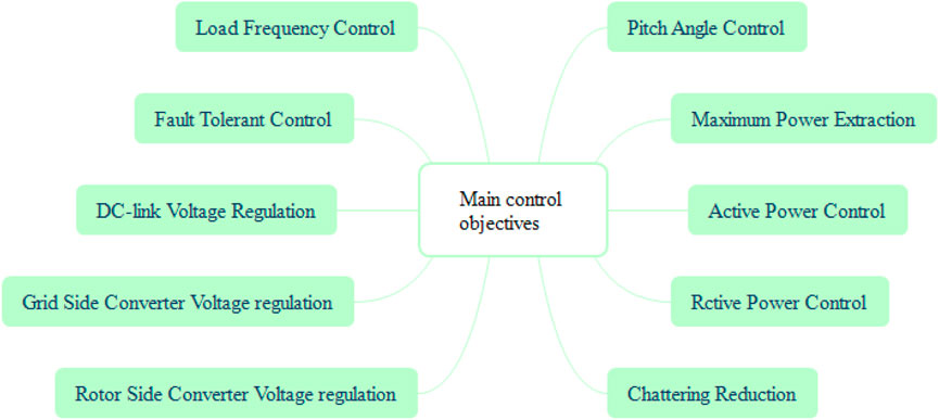
FIGURE 1. Main control objectives.
Two commonly used techniques for controlling the DFIG are field-orientation control (FOC) and direct power control (DPC) (Yessef et al., 2022). FOC with proportional–integral (PI) control is employed to make the machine behave like a direct current generator and decouple the machine’s variables (Jenkal et al., 2020). This technique remains prevalent due to its simplicity (Zellouma et al., 2023). However, the dynamic performance of the FOC-controlled DFIG is significantly influenced by the design of the PI parameters. While a classical PI controller can provide satisfactory performance in many wind energy conversion system (WECS) applications, it lacks robustness and adaptability to the changes in machine parameters that may arise from grid voltage drops, model inaccuracies, and unforeseen factors like temperature variations (Kerrouche et al., 2013).
The state-of-the-art control approaches such as sliding mode control (SMC) (Levant and Levantovsky, 1993; Amira et al., 2020; Ali et al., 2022; Mousavi et al., 2022) and backstepping (BSC) (Drhorhi et al., 2021; Hamid et al., 2021) can be employed to replace FOC and enhance the robustness of the WECS. These advanced control methods offer potential improvements in the overall performance of wind turbine systems based on DFIGs.
DPC has risen to prominence as a feasible substitute for the vector control technique due to its ability to overcome sensitivity issues associated with parameter variations. However, there are notable drawbacks to this control technique, which include significant power fluctuations and variable commutation frequencies. The existing literature contains a range of proposed approaches to mitigate these concerns. For instance, Mousavi et al. (2022) introduced a new sliding mode control (SMC) methodology for DPC in DFIG-based systems. Wang et al. (2016) suggested a resonance-based backstepping DPC strategy specifically designed for DFIG systems. Additionally, Yousefi-Talouki et al. (2019) presented a DPC technique for a matrix converter supplying a DFIG with a fixed switching frequency. Furthermore, a new DPC methodology for DFIGs has been described in Chojaa et al. (2023) that utilizes DSpace to boost the DFIG-WTS current quality by reducing undesirable harmonic at the current, torque, and active power signals. Rauf et al. (2022), Gulzar et al. (2023), and Syed and Khalid (2023) go beyond proposing the right techniques and approaches to overcome the impact of uncertainties, and they have suggested that the faced challenges can be effectively reduced by using a battery energy storage system.
The focus of the present contribution is to present a new approach that directly controls the power by incorporating the super-twisting algorithm (STA) for handling real-world wind conditions. The STA is a widely recognized and effectively controlled data processing technique. Unlike the conventional DPC method, the proposed customized DPC approach brings about significant differences. It replaces the traditional switching table and comparators with improved alternatives, thereby leading to a more efficient DPC strategy.
This study contributes valuable insights to the existing body of literature and presents several noteworthy conceptual ideas. The key highlights of this contribution can be summarized as follows:
• A robust control strategy using the super-twisting algorithm has been developed to control both the DFIG’s active and reactive powers.
• The proposed control design has been evaluated using actual wind speed data, providing a real-world context for analysis.
• A study comparing different aspects has been undertaken to evaluate the performance of the proposed method against other published works in terms of dynamic response time, accuracy, static error, reference tracking, stator current THD, and robustness to variations in system parameters.
The structure of this work is as follows: in Section 2, we present a model of the WECS, comprising the WT model and DFIG model. Section 3 formulates the problem by explaining the control configuration of the classic DPC and the objectives of the intelligent DPC controller. Section 4 describes the STA control, regulating both active and reactive powers. Section 5 analyzes the results obtained under a specific wind profile depicted in Figure 6; in addition, a comparison between the two controllers is conducted to evaluate their performances. Finally, Section 6 concludes this article.
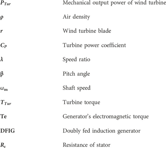
The mechanical output power of the wind turbine is given by the following equation (Jiang et al., 2022):
Equation (2) defines the turbine power coefficient (Heier, 2014):
The tip speed ratio (λ) is a function of the shaft speed (ωm) and the wind speed as
From
The equation of motion of single-mass modeling of the mechanical system is expressed as
where Te is the generator’s electromagnetic torque.
The doubly fed induction generator (DFIG) is a part of the wind conversion system illustrated in Figure 2. It offers easy control and provides a higher energy output when there are fluctuations in wind speed. The DFIG has two sets of windings: the stator windings and rotor windings. The windings of the stator are fixed and connected to the power grid, and those of the rotor are fed by a power converter that allows the control of the generator’s output.
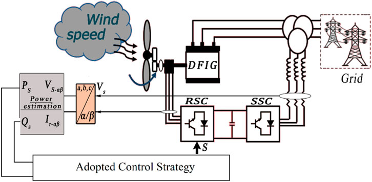
FIGURE 2. General supply configuration of the DFIG.
The electrical equations of the DFIG in the PARK frame are represented by the following equations (Abu-Rub et al., 2014):
where
where
The stator’s active and reactive powers are as follows (Chojaa et al., 2023):
The DFIG torque is a function of the stator currents and rotor flux as shown in Equation (10):
If the d and q axes are oriented in order to get the stator flux, the vector is aligned with the d axis (Mensou et al., 2020), therefore
and
The stator flux can be expressed as
By adopting the abovementioned mechanism, we can conclude that the electromagnetic torque and active power are functions of the rotor quadratic current. The direct and quadrature stator voltages can be written as per Equation (14) if we consider Rs is negligible and that
The expressions of the stator currents using rotor currents are
The expressions of the stator’s active and reactive powers are
The control principle involves adjusting the rotor-side converter control variables, such as the rotor voltage, in order to regulate the active and reactive powers of the DFIG. The PI regulator compares the desired active and reactive power references with the actual measured values and generates control signals to adjust the converter settings accordingly. Figure 3 illustrates the block diagram of the implemented controller. The term Kp is the proportional gain, and Ki represents the integral gain.
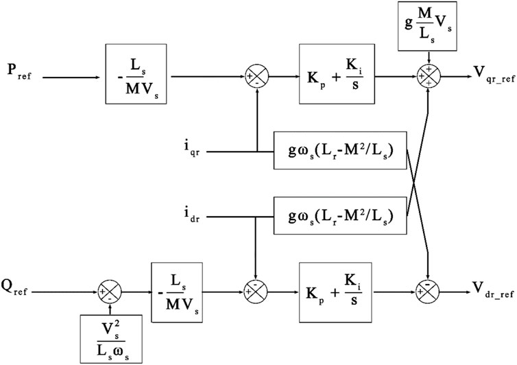
FIGURE 3. Configuration of the power control of the DFIG with PI.
The traditional DPC, as presented in Figure 4, is a control methodology commonly used for controlling wind turbine systems powered by the doubly fed induction generator (DFIG). In this control scheme, two hysteresis comparators [the active power hysteresis comparator (APHC) and reactive power hysteresis comparator (RPHC)] are used to directly control the DFIG machine’s stator active and reactive powers, and a switching table is applied to the converter on the rotor side (Djeriri et al., 2014; Chojaa et al., 2022).
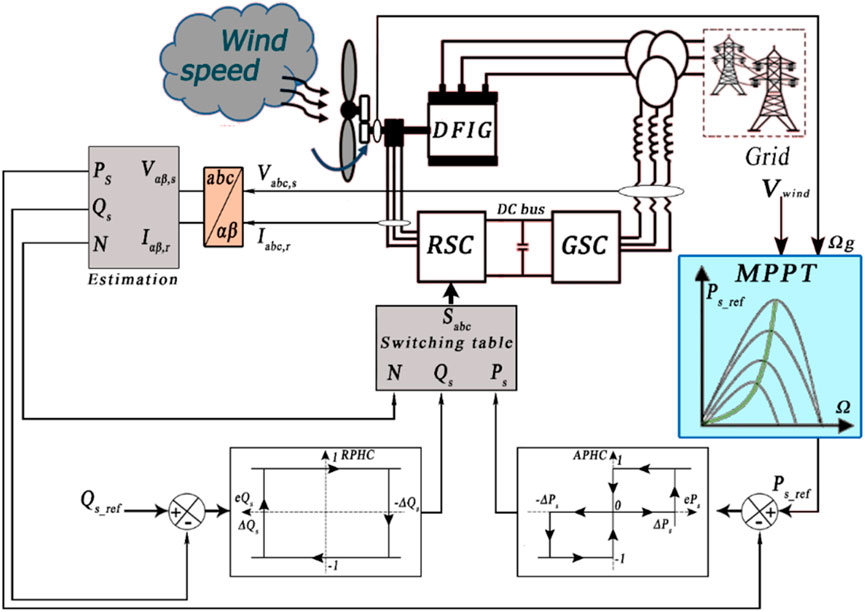
FIGURE 4. Classic DPC.
The switching table receives the rotor flux sector and errors Sp and Sq as the input and then each switching state, that is, Sa, Sb, and Sc, of the converter is stored, as shown in Table 1.
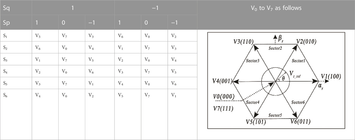
TABLE 1. Switching table concept.
The DPC controller aims to regulate the power outputs of the DFIG by directly controlling the converter switches on the rotor side. The hysteresis comparators monitor the deviation between the actual active and reactive powers and their reference values. Based on this deviation, the hysteresis comparators generate control signals that determine the switching states of the rotor-side converter. The switching table provides the appropriate voltage vectors to be applied to the rotor-side converter based on the control signals from the hysteresis comparators (Djeriri et al., 2014; Chojaa et al., 2023).
✓ Advantages:
• Fast dynamic response due to its direct control over the rotor-side converter switches. It can quickly regulate the active and reactive powers in response to changes in wind speed.
• Simplified control structure.
• Disassociated control of active and reactive powers.
✓ Disadvantages:
• Voltage and current harmonic: the traditional DPC can introduce harmonic in the grid due to the rapid switching of the rotor-side converter. This can lead to increased distortion in the voltage and current waveforms, requiring additional filtering or mitigation techniques.
• Limited control precision: the hysteresis comparators used in the traditional DPC have limited control precision due to the hysteresis band. This can result in slight fluctuations in active and reactive powers around the reference values.
• Complexity for higher power levels: The traditional DPC may become more complex to implement at higher power levels as the switching losses and thermal stresses on the power electronics increase with increased power ratings.
The objective is to track predefined power references by optimizing errors between the actual and desired values of the targeted parameters, optimizing the transient response and reducing the steady-state error. In order to achieve this, the proposed topology is to first decompose the active and reactive powers at the outer loop controller level in order to get the targeted errors and then apply the STA at the second level that is considered as the inner loop controller. Precisely, the aim of using the STA at this level is to act on the stator and rotor control voltages in order to control the active and reactive power flow. The STA continuously monitors the electrical power output of the DFIG-based WECS and adjusts the power reference signal as required to maintain the desired set point, while the DPC operates at a higher frequency than the STA to achieve a fast transient response. Overall, the control objective is to provide and demonstrate an efficient and stable operation of the DFIG-based WECS.
The idea of using the STA concept to control a variable-structure first-order system is to minimize the effect of the chattering phenomenon (Chiang et al., 2011; Hatlehol and Zadeh, 2022). This approach has similar properties to that of the controllers developed on the basis of the first-order sliding mode strategy (Levant and Levantovsky, 1993; Kelkoul and Boumediene, 2021; Elmorshedy et al., 2023). The controller based on the STA is made up of two components: one of them is discontinuous, while the other is continuous:
so that
and
where
The α, λ, and ρ satisfy the aforementioned conditions, with S0, C0, Km, and KM as positive constants (Chiang et al., 2011; Xiong et al., 2020).
If
This control is decomposed into a static algebraic component and an integrative component.
In Equation (16), we have
and from Equations (7), (8), we can conclude the first derivative of the rotor current in the d, q frame as
The error of Ps can be written as
where
The first derivative of the error expressed in Equation (23) is
Then, by using Equation (22), we have
Equation (26) shows the designed power controller based on the STA that aims to change the Vqr.
The error of Qs can be written as
where
The first derivative of the error expressed in Equation (28) is
Then, by using Equation (22), we have
We can design our super-twisting reactive power controller in order to change the Vdr as shown in Equation (30):
Figure 5 illustrates the graphical representation of our proposed control strategy, which is derived from Equation (26) and Equation (30). This control strategy incorporates the mathematical relationships defined in these equations to effectively regulate the system dynamics. By visually presenting the control strategy in Figure 5, a clear and concise understanding of the proposed approach is provided that allows further analysis and evaluation of its effectiveness in achieving the desired control objectives.
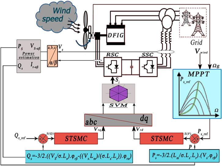
FIGURE 5. STA-DPC strategy.
The aim of the simulation is to examine the dynamic behavior of the system and to check the performance of the proposed control strategy that is developed on the basis of the super-twisting sliding mode and applied to a 1.5 KW DFIG using the MATLAB/Simulink. In Table A1, we highlight the DFIG’s parameters.
In this section, we have analyzed the behavior of the classical DPC and the STA-DPC using the wind profile shown in Figure 6.
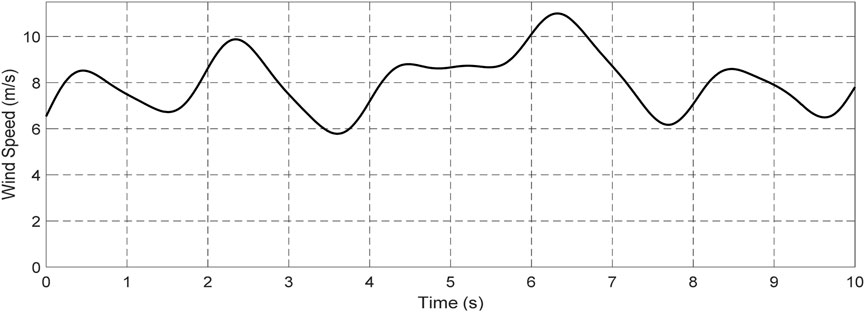
FIGURE 6. Real wind profile.
The power coefficient and speed ratio of the WT closely align with the behavior of the wind variation. These parameters adapt and respond to changes in wind conditions, as is illustrated in Figure 7.
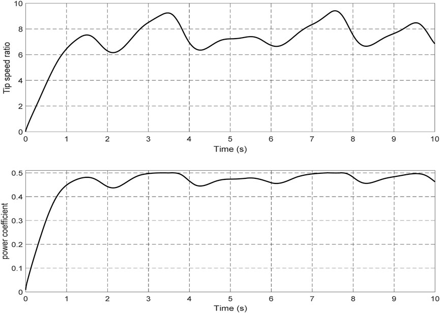
FIGURE 7. Speed ratio of wind turbine and power coefficient.
Figure 8 presents the rotor speed, offering valuable insights into the impact of wind on the rotational comportment of the system. The plot depicts the behavior of rotor speed over time, providing a clear representation of its dynamic nature.
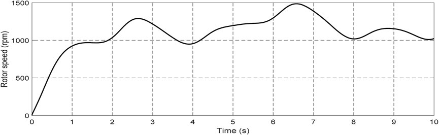
FIGURE 8. Rotor speed.
The electromagnetic torque behavior in Figure 9 provides valuable insights into the dynamics of the system. The torque exhibits a direct relationship with the quadrature rotor current (Figure 11), as variations in the quadrature current lead to corresponding changes in the electromagnetic torque. This relationship can be observed through the torque fluctuations, which coincide with the fluctuations in the quadrature rotor current.
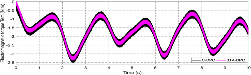
FIGURE 9. Electromagnetic torque Tem.
In Figure 10, it is evident that both the active and reactive powers exhibit a remarkable convergence toward their respective reference values. Notably, even a slight alteration in the wind speed can lead to a substantial variation in the extracted active power, ranging from 100 W to 600 W. It is clear that when the wind speed decreases, the value of active power (Ps) decreases as well, whereas it increases when the wind speed rises. Regarding the reactive power, the reference value remains fixed at zero, ensuring a unit power factor on the network side.
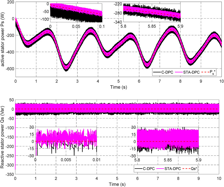
FIGURE 10. Active and reactive stator powers.
In the context of Figure 11, an insightful representation is provided regarding the rotor current components within the (d, q) frame. Notably, the quadrature rotor current, which is intricately connected to the active power, demonstrates a notable variation spanning from approximately 0.3 A to 1.8 A. This range illustrates the dynamic nature of the active power generation process. On the other hand, the direct rotor current remains relatively stable, maintaining a consistent value of around 2.7 A. This constant magnitude of the direct rotor current underscores its role in facilitating reactive power exchange within the system. Together, these findings shed light on the intricate relationship between the rotor currents, power generation, and their respective components in the (d, q) frame.
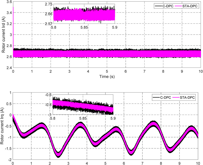
FIGURE 11. Direct and quadratic rotor currents.
The observations in Figure 12A–D highlight the correlation between the three parameters: stator currents, rotor currents, and the used wind profile. These figures clearly demonstrate the effect of wind variability on the current’s magnitude of the stator and rotor currents. Notably, the currents exhibit a maximum value of 3 A each, indicating the peak levels of electrical flow within the system. This dependence on the wind profile underscores the crucial role that the external environmental factors play in determining the operational performance of the system.
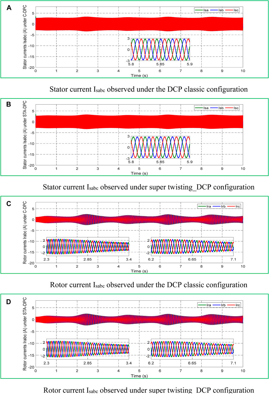
FIGURE 12. Stator and rotor current Isabc observed under the super-twisting_DCP configuration. (A) Stator current Isabc observed under the DCP classic configuration structure. (B) Stator current Isabc observed under the super-twisting_DCP configuration structure. (C) Rotor current Isabc observed under the DCP classic configuration structure. (D) Rotor current Isabc observed under the super-twisting_DCP configuration structure.
Figure 13 visually represents the power factor of the system, revealing an approximate value of 1. The plot also exhibits noticeable ripples that are directly linked to the system’s operation and the fluctuations in wind speed.
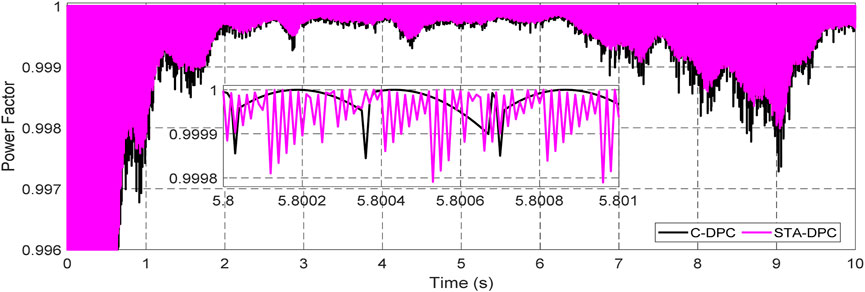
FIGURE 13. Power factor.
Figure 14 represents a result of the fast Fourier transform (FFT) analyses of the current waves generated at the DFIG stator for both the used methods. The following key parameters were considered.
✓ Sampling rate (Fs): The sampling rate is twice the maximum frequency to avoid aliasing.
✓ Window function: Hamming is a window function that is applied to the time-domain signal before performing the FFT.
✓ Window length (N): The window length is the number of data points used in each FFT calculation.
✓ Overlap: 50%.
✓ Zero Padding: Two zeros were added to the end of the time-domain signal before performing the FFT.
✓ Averaging: Multiple FFTs are averaged to reduce the effects of noise.
✓ Window Scaling: A scaling factor of 1.5 was applied to correct the amplitude loss due to windowing.
✓ DC component handling: The DC (0 Hz) component was excluded in the FFT results.
✓ Normalization: FFT results were normalized to obtain the power spectral density values.

FIGURE 14. Net improvement in the THD of the current induced using the two methods.
Notably, the results clearly indicate that the THD achieved through the implementation of the STA-DPC is significantly lower than the THD observed with the classical DPC. This finding highlights the improved harmonic performance and superior quality of the generated current.
While Figure 14 does not offer a direct comparison with specific standards such as IEEE 519, it serves as a fundamental assessment of the harmonic behavior. Table 2 compares the presented study with other studies that have been published according to the THD of electric stator current.
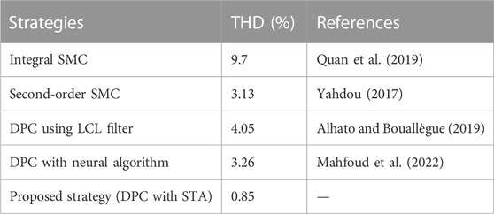
TABLE 2. Comparison of the obtained THD with those recorded in the literature.
This research presents a thorough investigation aimed to highlight the advantages of utilizing doubly fed induction generators (DFIGs) in wind energy conversion systems (WECSs) in association with a robust control strategy known as the super-twisting algorithm (STA).
By implementing the STA based on the direct power control (DPC) method, several significant benefits are achieved relative to the conventional DPC approach. One of the notable advantages is the reduction of total harmonic distortion (THD) in the stator current of the DFIG. This reduction indicates that the STA-DPC effectively mitigates harmonic components and enhances the overall quality of the stator current. Consequently, the adoption of the STA-DPC leads to an improvement in the overall system performance, a decrease in electrical noise, and a power quality enhancement in the used wind energy conversion system.
The original contributions presented in the study are included in the article/Supplementary Material; further inquiries can be directed to the corresponding authors.
AH: data curation, formal analysis, and manuscript writing–original draft. AMo: manuscript writing–original draft and software. AMi: manuscript writing–original draft and methodology. HC: manuscript writing–review and editing. CD: manuscript writing–review and editing. MG: investigation, methodology, and manuscript writing–review and editing. MA: manuscript writing–review and editing. MK: manuscript writing–review and editing.
The author(s) declare that no financial support was received for the research, authorship, and/or publication of this article.
The authors at the King Fahd University of Petroleum and Minerals (KFUPM) would like to acknowledge the support from KFUPM. MA would like to acknowledge the support by the Deanship of Scientific Research through King Khalid University funded by the Large Group Research Project RGP2/239/44.
The authors declare that the research was conducted in the absence of any commercial or financial relationships that could be construed as a potential conflict of interest.
All claims expressed in this article are solely those of the authors and do not necessarily represent those of their affiliated organizations, or those of the publisher, editors, and reviewers. Any product that may be evaluated in this article, or claim that may be made by its manufacturer, is not guaranteed or endorsed by the publisher.
Abu-Rub, H., Malinowski, M., and Al-Haddad, K. (2014). Power electronics for renewable energy systems, transportation and industrial applications. John Wiley & Sons, Hoboken, NJ, USA, | IEEE eBooks | IEEE Xplore
Al-Muhaini, M., Bizrah, A., Heydt, G., and Khalid, M. (2019). Impact of wind speed modelling on the predictive reliability assessment of wind-based microgrids. IET Renew. Power Gener. 13 (15), 2947–2956. doi:10.1049/iet-rpg.2019.0596
Algarni, S., Tirth, V., Alqahtani, T., Alshehery, S., and Kshirsagar, P. (2023). Contribution of renewable energy sources to the environmental impacts and economic benefits for sustainable development. Sustain. Energy Technol. Assessments 56, 103098. doi:10.1016/j.seta.2023.103098
Alhato, M. M., and Bouallègue, S. (2019). Direct power control optimization for doubly fed induction generator based wind turbine systems. Math. Comput. Appl. 24 (3), 77. doi:10.3390/mca24030077(n.d.) MCA | Free Full-Text
Ali, M., Amrr, S. M., and Khalid, M. (2022). Speed control of a wind turbine–driven doubly fed induction generator using sliding mode technique with practical finite-time stability. Front. Energy Res. 10, 970755. doi:10.3389/fenrg.2022.970755
Amira, L., Tahar, B., and Abdelkrim, M. , “Sliding mode control of doubly-fed induction generator in wind energy conversion system,” in 2020 8th International Conference on Smart Grid (IcSmartGrid), Paris, France, June, 2020, 96–100.
Anika, O. C., Nnabuife, S. G., Bello, A., Okoroafor, E. R., Kuang, B., and Villa, R. (2022). Prospects of low and zero-carbon renewable fuels in 1.5-degree net zero emission actualisation by 2050: A critical review. Carbon Capture Sci. Technol. 5, 100072. doi:10.1016/j.ccst.2022.100072
Chen, Z., and Blaabjerg, F. (2009). Wind farm—a power source in future power systems. Renew. Sustain. Energy Rev. 13 (6), 1288–1300. doi:10.1016/j.rser.2008.09.010
Chiang, H.-K., Lin, W.-B., Chang, Y.-C., and Fang, C.-C. (2011). Super-twisting second-order sliding mode control for a synchronous reluctance motor. Artif. Life Robotics 16, 307–310. doi:10.1007/s10015-011-0935-7
Choe Wei Chang, C., Jian Ding, T., Jian Ping, T., Chia Chao, K., and Bhuiyan, M. A. S. (2022). Getting more from the wind: recent advancements and challenges in generators development for wind turbines. Sustain. Energy Technol. Assessments 53, 102731. doi:10.1016/j.seta.2022.102731
Chojaa, H., Derouich, A., Chehaidia, S. E., Zamzoum, O., Taoussi, M., Benbouhenni, H., et al. (2022). Enhancement of direct power control by using artificial neural network for a doubly fed induction generator-based WECS: an experimental validation. Electronics 11 (24), 4106. doi:10.3390/electronics11244106
Chojaa, H., Derouich, A., Zamzoum, O., Mahfoud, S., Taoussi, M., Albalawi, H., et al. (2023). A novel DPC approach for DFIG-based variable speed wind power systems using DSpace. IEEE Access 11, 9493–9510. doi:10.1109/access.2023.3237511
Chu, J., Shao, C., Emrouznejad, A., Wu, J., and Yuan, Z. (2021). Performance evaluation of organizations considering economic incentives for emission reduction: A carbon emission permit trading approach. Energy Econ. 101, 105398. doi:10.1016/j.eneco.2021.105398
Cordroch, L., Hilpert, S., and Wiese, F. (2022). Why renewables and energy efficiency are not enough - the relevance of sufficiency in the heating sector for limiting global warming to 1.5 °C. Technol. Forecast. Soc. Change 175, 121313. doi:10.1016/j.techfore.2021.121313
Desalegn, B., Gebeyehu, D., and Tamirat, B. (2022). Wind energy conversion technologies and engineering approaches to enhancing wind power generation: A review. Heliyon 8 (11), e11263. doi:10.1016/j.heliyon.2022.e11263
Djeriri, Y., Meroufel, A., Massoum, A., and Boudjema, Z. (2014). Direct power control of a Doubly Fed Induction Generator based wind energy conversion systems including a storage unit. J. Electr. Eng. 14, 196–204.
Dong, H., and Zhang, L. (2023). Transition towards carbon neutrality: forecasting Hong Kong’s buildings carbon footprint by 2050 using a machine learning approach. Sustain. Prod. Consum. 35, 633–642. doi:10.1016/j.spc.2022.12.014
Drhorhi, I., El Fadili, A., Berrahal, C., Lajouad, R., El Magri, A., Giri, F., et al. (2021). “Chapter 11 - adaptive backstepping controller for DFIG-based wind energy conversion system,” in Backstepping control of nonlinear dynamical systems. Editors S. Vaidyanathan, and A. T. Azar (Cambridge, MA, USA: Academic Press), 235–260.
Elmorshedy, M. F., Selvam, S., Mahajan, S. B., and Almakhles, D. (2023). Investigation of high-gain two-tier converter with PI and super-twisting sliding mode control. ISA Trans. 138, 628–638. doi:10.1016/j.isatra.2023.03.020
Galimova, T., Ram, M., and Breyer, C. (2022). Mitigation of air pollution and corresponding impacts during a global energy transition towards 100% renewable energy system by 2050. Energy Rep. 8, 14124–14143. doi:10.1016/j.egyr.2022.10.343
Gulzar, M. M., Iqbal, A., Sibtain, D., and Khalid, M. (2023). An innovative converterless solar PV control strategy for a grid connected hybrid PV/wind/fuel-cell system coupled with battery energy storage. IEEE Access 11, 23245–23259. doi:10.1109/access.2023.3252891
Hamid, C., Derouich, A., Hallabi, T., Zamzoum, O., Taoussi, M., Rhaili, S., et al. (2021). Performance improvement of the variable speed wind turbine driving a DFIG using nonlinear control strategies. Int. J. Power Electron. Drive Syst. (IJPEDS) 12 (4), 2470–2482. doi:10.11591/ijpeds.v12.i4.pp2470-2482
Hamid, C., Derouich, A., Yassine, B., Chetouani, E., Meghni, B., Chehaidia, S. E., et al. (2022). Comparative study of mppt controllers for a wind energy conversion system, Advanced Technologies for Humanity, Springer, Berlin, Germany, 300–310.
Hatlehol, M. U., and Zadeh, M. (2022). Super-twisting algorithm second-order sliding mode control of a bidirectional DC-to-DC converter supplying a constant power load. IFAC-PapersOnLine. 55 (31), 287–294. doi:10.1016/j.ifacol.2022.10.444
Heier, S. (2014). Grid integration of wind energy: Onshore and offshore conversion systems. 3rd Edition. Wiley. Hoboken, NJ, USA, Wiley.Com
Jenkal, H., Bossoufi, B., Boulezhar, A., Lilane, A., and Hariss, S. (2020). Vector control of a doubly fed induction generator wind turbine. Mater. Today Proc. 30, 976–980. doi:10.1016/j.matpr.2020.04.360
Jiang, Y., Liu, S., Zao, P., Yu, Y., Zou, L., Liu, L., et al. (2022). Experimental evaluation of a tree-shaped quad-rotor wind turbine on power output controllability and survival shutdown capability. Appl. Energy 309, 118350. doi:10.1016/j.apenergy.2021.118350
Kelkoul, B., and Boumediene, A. (2021). Stability analysis and study between classical sliding mode control (SMC) and super twisting algorithm (STA) for doubly fed induction generator (DFIG) under wind turbine. Energy 214, 118871. doi:10.1016/j.energy.2020.118871
Kerrouche, K., Mezouar, A., and Belgacem, Kh. (2013). Decoupled control of doubly fed induction generator by vector control for wind energy conversion system. Energy Procedia 42, 239–248. doi:10.1016/j.egypro.2013.11.024
Levant, A., and Levantovsky, L. (1993). Sliding order and sliding accuracy in sliding mode control. Int. J. Control 58, 1247–1263. doi:10.1080/00207179308923053
Loulijat, A., Chojaa, H., El marghichi, M., Ettalabi, N., Hilali, A., Mouradi, A., et al. (2023). Enhancement of LVRT ability of DFIG wind turbine by an improved protection scheme with a modified advanced nonlinear control loop. Processes 11 (5), 1417. doi:10.3390/pr11051417(n.d.) Processes | Free Full-Text
Mahfoud, S., Derouich, A., Ouanjli, N. E., and Mahfoud, M. E. (2022). Enhancement of the direct torque control by using artificial neuron network for a doubly fed induction motor. Intelligent Syst. Appl. 13, 200060. doi:10.1016/j.iswa.2022.200060
Mensou, S., Essadki, A., Nasser, T., Idrissi, B. B., and Ben Tarla, L. (2020). Dspace DS1104 implementation of a robust nonlinear controller applied for DFIG driven by wind turbine. Renew. Energy 147, 1759–1771. doi:10.1016/j.renene.2019.09.042
Mousavi, Y., Bevan, G., Kucukdemiral, I. B., and Fekih, A. (2022). Sliding mode control of wind energy conversion systems: trends and applications. Renew. Sustain. Energy Rev. 167, 112734. doi:10.1016/j.rser.2022.112734
Quan, Y., Hang, L., He, Y., and Zhang, Y. (2019). Multi-resonant-based sliding mode control of DFIG-based wind system under unbalanced and harmonic network conditions. Appl. Sci. 9 (6), 1124. doi:10.3390/app9061124
Rauf, A., Kassas, M., and Khalid, M. (2022). Data-Driven optimal battery storage sizing for grid-connected hybrid distributed generations considering solar and wind uncertainty. Sustainability 14 (17), 11002. doi:10.3390/su141711002
Saha, S., Saini, G., Mishra, S., Chauhan, A., and Upadhyay, S. (2022). A comprehensive review of techno-socio-enviro-economic parameters, storage technologies, sizing methods and control management for integrated renewable energy system. Sustain. Energy Technol. Assessments 54, 102849. doi:10.1016/j.seta.2022.102849
Steane, E., and Clausen, D. (2022). “9.16- local action on global warming and renewable energy,” in Comprehensive renewable energy. Editor T. M. Letcher (Oxford, UK: Elsevier), 221–233.
Syed, M. A., and Khalid, M. (2023). An intelligent model predictive control strategy for stable solar-wind renewable power dispatch coupled with hydrogen electrolyzer and battery energy storage. Int. J. Energy Res. 2023, 1–17. doi:10.1155/2023/45310542023
Wang, X., Sun, D., and Zhu, Z. Q. , “Resonant based backstepping direct power control strategy for DFIG under both balanced and unbalanced grid conditions,” in 2016 IEEE Energy Conversion Congress and Exposition (ECCE), Milwaukee, WI, USA, September, 2016, 1–8.
Xiong, L., Li, P., and Wang, J. (2020). High-order sliding mode control of DFIG under unbalanced grid voltage conditions. Int. J. Electr. Power and Energy Syst. 117, 105608. doi:10.1016/j.ijepes.2019.105608
Yahdou, A. (2017). Second order sliding mode control of a dual-rotor wind turbine system by employing a matrix converter. J. Electr. Eng. 16 (3).(n.d.) (9) (PDF)
Yessef, M., Bossoufi, B., Taoussi, M., Lagrioui, A., and Chojaa, H. (2022). Overview of control strategies for wind turbines: ANNC, FLC, SMC, BSC, and PI controllers. Wind Eng. 46 (6), 1820–1837. doi:10.1177/0309524x221109512
Yousefi-Talouki, A., Zalzar, S., and Pouresmaeil, E. (2019). Direct power control of matrix converter-fed DFIG with fixed switching frequency. Sustainability 11, 2604. doi:10.3390/su11092604
Zellouma, D., Bekakra, Y., and Benbouhenni, H. (2023). Field-oriented control based on parallel proportional–integral controllers of induction motor drive. Energy Rep. 9, 4846–4860. doi:10.1016/j.egyr.2023.04.008

TABLE A1. Parameters of the DFIG.
Keywords: wind energy conversion system, STA-DPC, DPC, doubly fed induction generator, wind turbine
Citation: Hadoune A, Mouradi A, Mimet A, Chojaa H, Dardabi C, Gulzar MM, Alqahtani M and Khalid M (2023) Optimizing direct power control of DFIG-based WECS using super-twisting algorithm under real wind profile. Front. Energy Res. 11:1261902. doi: 10.3389/fenrg.2023.1261902
Received: 19 July 2023; Accepted: 25 September 2023;
Published: 12 October 2023.
Edited by:
Juan P. Amezquita-Sanchez, Autonomous University of Queretaro, MexicoReviewed by:
M. Kowsalya, VIT University, IndiaCopyright © 2023 Hadoune, Mouradi, Mimet, Chojaa, Dardabi, Gulzar, Alqahtani and Khalid. This is an open-access article distributed under the terms of the Creative Commons Attribution License (CC BY). The use, distribution or reproduction in other forums is permitted, provided the original author(s) and the copyright owner(s) are credited and that the original publication in this journal is cited, in accordance with accepted academic practice. No use, distribution or reproduction is permitted which does not comply with these terms.
*Correspondence: Muhammad Majid Gulzar, bXVoYW1tYWQuZ3VsemFyQGtmdXBtLmVkdS5zYQ==; Muhammad Khalid, bWtoYWxpZEBrZnVwbS5lZHUuc2E=
Disclaimer: All claims expressed in this article are solely those of the authors and do not necessarily represent those of their affiliated organizations, or those of the publisher, the editors and the reviewers. Any product that may be evaluated in this article or claim that may be made by its manufacturer is not guaranteed or endorsed by the publisher.
Research integrity at Frontiers
Learn more about the work of our research integrity team to safeguard the quality of each article we publish.