- 1Institute of Refrigeration and Cryogenics and Engineering Research Center of Solar Power and Refrigeration, MOE China, Shanghai Jiao Tong University, Shanghai, China
- 2Shanghai Nuotong New Energy Technology Co., Ltd., Shanghai, China
Water is a promising working fluid for high-temperature heat pumps (HTHPs) with the advantages of being cheap, safe, stable, environmentally friendly, non-toxic, and non-flammable. HTHPs using water as a refrigerant not only can reduce greenhouse gas emissions in the industrial sectors by recovering waste heat but also have no adverse effect on the environment if the refrigerant leaks. This article evaluates the safety, energy, and exergy performance of six designed HTHP configurations with water refrigerant by analyzing the discharge superheat, power consumption, heating capacity, COP, and exergy efficiency—at different condensation and evaporation temperatures. The results indicated that water injection and intercooling can effectively decrease the discharge superheat to ensure safety performance. Among these systems, two-stage cycles can supply higher output temperatures and have better system performance compared to single-stage cycles at high-temperature lifts and large compression ratio conditions. The two-stage system with a flash tank (TS-FT) has the biggest heating capacity, the best COP, and the best exergy efficiency. With an evaporation temperature of 80°C and condensation temperature of 140°C, the COP is 4.14 and the exergy efficiency is 70.9% for the TS-FT. Compared with the single-stage ordinary system (SS-OS), the COP of the TS-FT has an increment of 36.6%. The exergy efficiency of the TS-FT is 19.8% higher than that of the SS-OS. Considering the aforementioned theoretical analysis, the TS-FT with the best safety, energy, and exergy performance is the optimal HTHP system with water refrigerant for high-temperature applications.
1 Introduction
In the last decade, reducing carbon dioxide emissions to prevent global warming has attracted wide attention around the world. Using energy-saving technologies to reduce primary energy consumption is an important way to prevent global warming. The heat pump is an effective energy-saving technology, which can significantly reduce primary energy consumption by recycling and utilizing waste heat or any other kind of low-grade thermal heat (Arpagaus et al., 2016; Xu and Wang, 2016). Furthermore, compared with absorption and adsorption heat pumps, vapor compression heat pumps, which are available in a large variety of sizes, have been most widely used in commercial and industrial applications to help reduce carbon dioxide emissions recently (Arpagaus et al., 2018; Liu et al., 2022). So, to satisfy various application demands and save energy, many vapor compression heat pump systems with different refrigerants have been investigated, developed, and used in various industrial scenarios (Bamigbetan et al., 2017; Jiang et al., 2022). However, as the core of the vapor compression heat pump system, the refrigerant not only limits the performance of heat pumps but also greatly impacts global warming. Due to this reason, refrigerant selection plays the most important role in the design process of a heat pump system (Calm and Hourahan, 1999; Calm, 2008). In the past 200 years, the history of refrigerant development can be divided into four stages with a different focus. In 2016, the 28th Meeting of the Parties to the Montreal Protocol passed the Kigali Amendment, which is aimed at reducing greenhouse gases such as hydrofluorocarbons (HFCs) and has been effective from 1 January 2019 (Heath, 2017). The adoption of the Kigali Amendment indicates that the development of refrigerants has officially entered the fourth stage of reducing global warming. By limiting 18 kinds of HFCs, the Kigali Amendment is expected to reduce HFC emissions by 88% and lower global warming by 0.5°C at the end of the 21st century. So, low-global warming potential (GWP) refrigerants, such as natural refrigerants (Bamigbetan et al., 2018; Schlemminger et al., 2019) and novel hydrofluoroolefins (HFOs) (Arpagaus et al., 2019; Arpagaus and Stefan, 2019; Watanabe et al., 2019), have recently become more and more popular in vapor compression heat pump systems. These heat pumps are investigated to satisfy various temperature demands in different systems with high performance. As the representative of natural refrigerants, water plays an important role in the low-GWP refrigerant heat pump research, especially when the output temperature is above 100°C.
Water is a cheap, safe, and stable refrigerant with no toxicity or flammability. In addition, it has great theoretical performance and potential in high-temperature conditions. The high-temperature heat pump (HTHP) systems using water as a refrigerant have larger compression ratios and larger volumetric flow rates simultaneously (Wu et al., 2021). They have high discharge temperatures, which not only cause deformation of the rotors and housings but also threaten the long-term security and stability of systems (Stosic, 2015). To realize the application of water in HTHPs, all the aforementioned problems need to be addressed. To satisfy the large compression ratio and the large volumetric flow rate simultaneously, the twin-screw compressor is the best compressor type for a water refrigerant (Hu et al., 2018). However, its adiabatic efficiency has an optimal value as the compression ratio is close to the designed value. The volumetric efficiency of the twin-screw compressor also decreases with the increase in compression ratio (Shen et al., 2016). When the compression ratio is too large, the adiabatic and the volumetric efficiency decrease rapidly, seriously affecting system performance. In addition, refrigerant injection and intercooling are great solutions to decrease high discharge temperature and improve system performance (Shen et al., 2014; Wu et al., 2020a).
To solve the aforementioned problems and better apply the water refrigerant in the HTHP system, many scholars are trying to study and investigate the water vapor HTHP (WV-HTHP) through theoretical analysis and experimental research. Madsboell et al. (2014) designed a centrifugal water vapor compressor for industrial heat pump applications to supply hot water of 90°C–110°C, which has a capacity of 100–500 kW with a temperature lift of 25°C–30°C per stage. They introduced the performance of the centrifugal compressor but did not use it in a heat pump system. Shen et al. (2014) designed and analyzed a single-stage water vapor heat pump system with a water-jet screw-type steam compressor. Using a water spray makes the discharge water vapor reach its saturation state and meet its high-temperature lift requirements. At an evaporation temperature of 75°C and temperature lift of 55°C, the system has a calculated COP of 6. Larminat et al. (2014) built and tested a prototype of a single-stage HTHP with water refrigerant, which uses a two-stage centrifugal compressor. This heat pump is designed for 700 kW heating capacity at 90°C evaporation and 130°C condensation. The prototype was successfully tested with a COP of 5.5 at the design condition. Chamoun et al. (2011), Chamoun et al. (2012), and Chamoun et al. (2014) presented a new single-stage water vapor heat pump system and introduced a prototype of this heat pump. Their simulation results showed that when the source heat temperature was 94°C at a constant volume flow rate of 72 m3 h−1, the output heating capacity reached 390 kW with a COP of 5.5. Wu et al. (2019b) also presented a WV-HTHP system with a single stage for waste heat recovery from the 80°C–90°C heat source to support an efficient 120°C–130°C hot water supply. Then, they tried to improve the hot water output temperature and increased the condensation temperature to 150°C with a temperature lift of 65°C (Wu et al., 2019a). By comparison with the traditional refrigerant (R245fa), hydrocarbons (R600 and R601), and novel HFOs (R1234ze(Z) and R1336mzz(Z)), they found that water refrigerant has the best potential in HTHPs (Wu et al., 2020b).
Although the study of HTHP using water as a refrigerant is a research hotspot currently, almost all the aforementioned research is experimental and based on a single-stage heat pump system with little difference, such as different compressor types and different water-injection loops. They just focused on COP and heating capacity. It makes sense to carry out a theoretical analysis of the performance of different HTHP configurations with water refrigerant systematically, including the safety, energy, and exergy performance. In particular, the performance characteristics of the water refrigerant in a two-stage compression heat pump system are demonstrated and analyzed. Herein, two tasks are included to analyze the system performance of the WV-HTHP with different configurations. First, WV-HTHP systems with different pieces of auxiliary equipment were introduced and compared, and the differentiated role of these pieces of auxiliary equipment in the system is highlighted. Second, the thermodynamic analysis and performance prediction were finished for WV-HTHP systems with different configurations, and the application characteristics and potential of the systems with different configurations are indicated. They will promote the investigation and popularize the application of WV-HTHPs, which are conducive to environmental protection and energy conservation.
2 Heat pump configurations
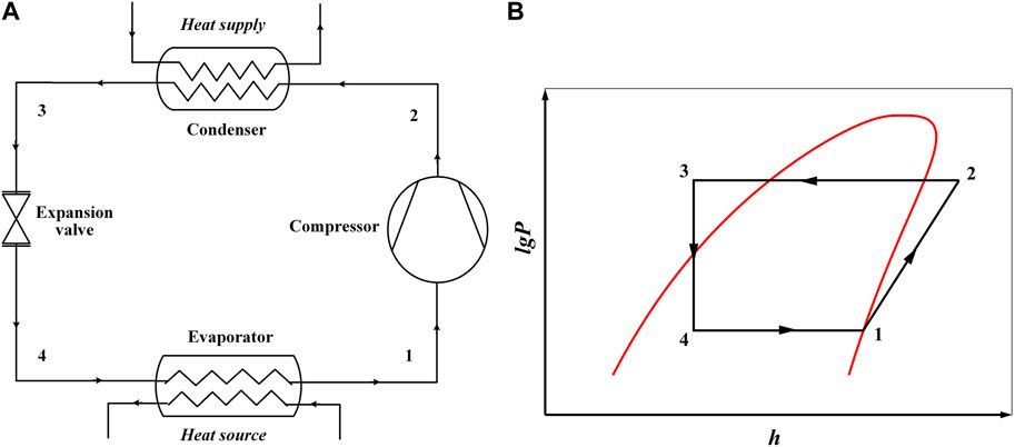
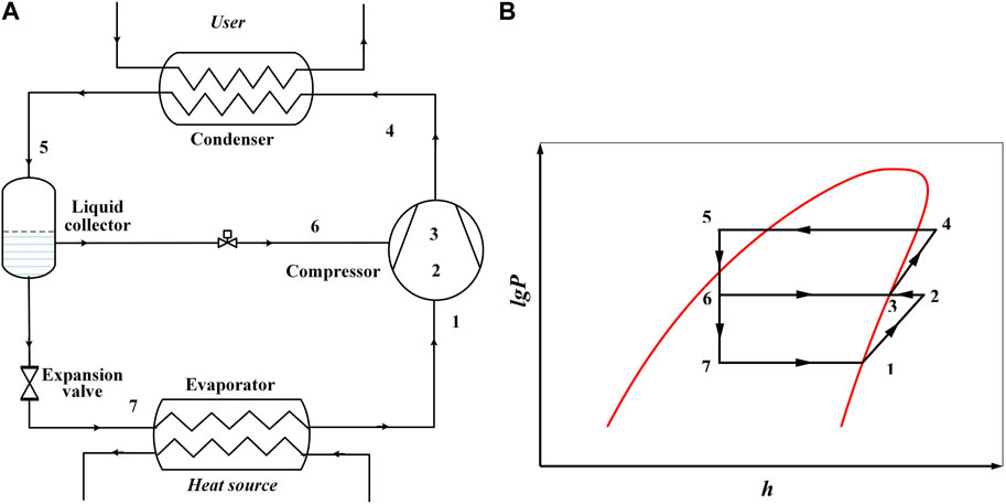
To analyze the performance of different WV-HTHP configurations, two single-stage and four two-stage WV-HTHP systems with different pieces of auxiliary equipment were refactored. In addition to the six designed systems, a single-stage ordinary system (SS-OS) is used as the baseline in theoretical analysis, as shown in Figure 1. Figure 2 presents the schematic diagram of the single-stage system with water injection (SS-WI) and its corresponding p–h diagram. Water injection in the compressor chamber was designed to decrease discharge temperature. By injecting water into the compressor chamber from the liquid collector, superheat of compressed steam is decreased during the compression process. Figure 3 shows the schematic and p–h diagrams of the single-stage system with an ejector (SS-ES). The ejector was added in this cycle to increase suction pressure. When steam is cooled to the saturation condition with constant pressure in the gas cooler, it is divided into two streams. One is used as driving steam to eject evaporation steam. The other flows into the evaporator to recover waste heat. After being ejected by the high-pressure driving steam, the steam sucked by the compressor has a higher pressure than evaporation pressure. It helps decrease the compression ratio and power consumption per unit mass.
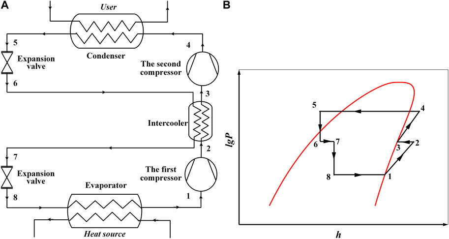
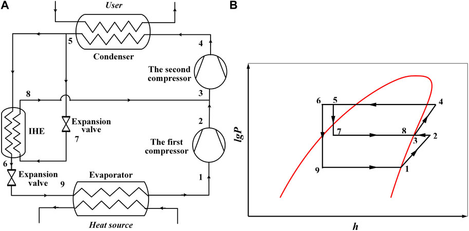
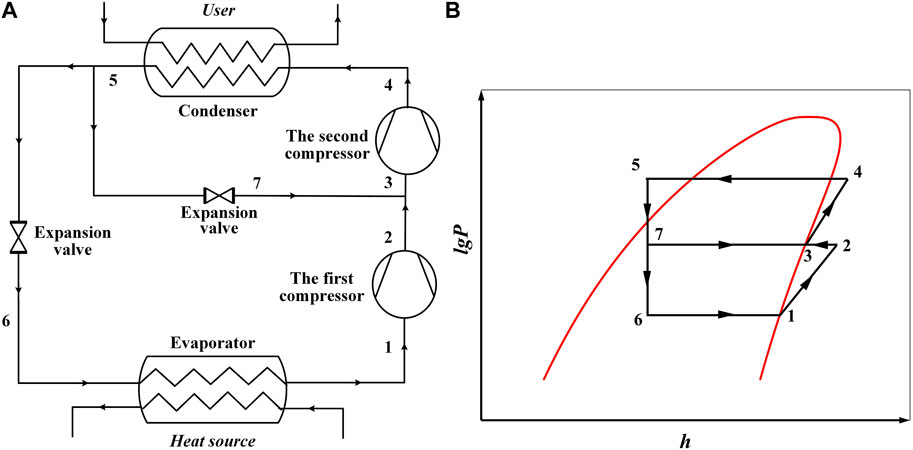
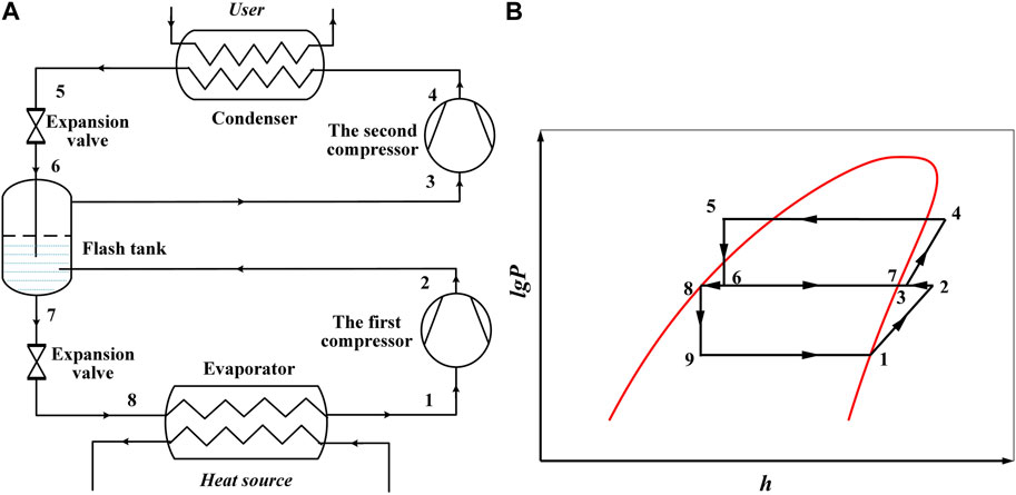
Compared with single-stage systems, two-stage systems can satisfy a larger compression ratio and achieve a higher temperature lift. Four two-stage systems were constructed. Figures 4–7 present the schematic and p–h diagrams of the designed two-stage WV-HTHP systems. Figure 4 shows the two-stage system with an intercooler (TS-IC) and its corresponding p–h diagram. The intercooler between two compressors was used to decrease the suction temperature of the second compressor, which helped lower the practical discharge temperature. Figure 5 presents the two-stage system with an internal heat exchanger (TS-IHE) and its corresponding p–h diagram. The IHE was designed to provide wet-steam injection during the two-stage compression, which benefits the discharge temperature decrease and the system performance improvement. Figure 6 shows the two-stage system with water injection (TS-WI) and its corresponding p–h diagram, which is similar to the SS-WI. The discharge temperature is decreased by directly injecting the condensed liquid during the two-stage compression to lower the superheat. Figure 7 displays the two-stage system with a flash tank (TS-FT) and its corresponding p–h diagram. The flash tank was added to decrease the middle temperature by the endothermic effect of flash evaporation. In addition, the condensed liquid also produces steam during the flash process, which increases the mass flow rate flowing into the second compressor.
3 Thermodynamic analysis
To analyze the safety, energy, and exergy performance of different WV-HTHP systems, thermodynamic models are developed to simulate their performance. In these models, the following assumptions were made:
1) The refrigerant evaporates and condenses at the constant pressure in the evaporator and condenser, respectively
2) The refrigerant expands at constant enthalpy in the expansion valve
3) The refrigerant is at a saturation state at the outlet of the evaporator
4) The refrigerant has a 5°C subcooling at the outlet of the condenser
5) For SS-WI and two-stage systems, the steam is at the saturation state with the middle pressure
6) The compression ratio is kept below 12 per one stage
7) During the compression process, the steam leakage is from the discharge side to the suction side
8) During the heat exchange process, the heat transfer efficiency is 100%
Some of the equations used in the calculation process are shown as follows.
For the compression process, the suction mass flow rate for the compressor (single-stage systems) and the first compressor (two-stage systems), msteam,suc, in kg·s-1, is calculated by the following equation:
where Vth is the theoretical volumetric flow rate of the twin-screw compressor in m3·s−1; ρsuc is the density of suction steam in kg·m−3; and ηvol is the volumetric efficiency of the twin-screw compressor.
The volumetric efficiency of the twin-screw compressor, ηvol, is obtained from the work of Liu et al. (2012), as shown in the following equation:
where pdis is the discharge pressure of the compressor and psuc is the suction pressure of the compressor in kPa.
The discharged mass flow rate of steam for the compressor (single-stage systems) and the second compressor (two-stage systems), msteam,dis, in kg·s-1, is calculated by the following equations.
For the SS-OS, SS-ES, and TS-IC,
For the SS-WI,
For the TS-IHE,
For the TS-WI,
For the TS-FT,
where hi (i = 2, 3, 6, 7, 8) represents the enthalpy at the state point of i as marked in Figures 1–7.
The system power consumption, W, in kW, is calculated by the following equation:
where hdis represents the discharge enthalpy of steam in kJ·kg-1; hsuc represents the suction enthalpy of steam in kJ·kg-1; and ηm and ηele represent the mechanical and electrical efficiencies of the compressor, respectively.
The discharge enthalpy of steam of each compressor, hdis, in kJ·kg-1, is calculated by the following equation:
where ηis is the isentropic efficiency of the twin-screw compressor and his represents the enthalpy of steam after the isentropic compression in kJ·kg−1.
The isentropic efficiency of the twin-screw compressor is fitted from data given by Tian et al. (2017), as shown in the following equation:
The discharge superheat temperature of steam for the systems, tsuper, in °C, is calculated by the following equation:
where tdis is the discharge temperature of steam for the compressor in °C and tsat is the saturation temperature of steam at the discharge pressure in °C.
For the heat exchangers, such as the evaporator, condenser, and gas cooler used in the systems, the heat exchange capacity and the heat balance are calculated by the following equation:
where Qexc represents the heat exchange capacity for different heat exchangers in kW; hin and hout represent the enthalpy at the inlet and outlet of different heat exchangers in kJ·kg-1, respectively; tin and tout represent the pressurized medium water temperature at the inlet and outlet of different heat exchangers in °C, respectively; msteam represents the mass flow rate flowing through different heat exchangers in kg·s-1; mmedium represents the mass flow rate of pressurized medium water in different heat exchangers in kg·s-1; and cp represents the specific heat of pressurized medium water in kJ·(kg·°C)−1.
The system heating capacity, Q, in kW, is calculated by the following equations.
For the SS-OS, SS-WI, TS-IC, TS-IHE, TS-WI, and TS-FT,
For the SS-ES,
The COP of the systems is calculated by the following equation:
Exergy efficiency is defined as the ratio of the total exergy output, Eout, to the total exergy input, Ein, of the systems, as shown in the following equation:
The total exergy output, Eout, and the total exergy input, Ein, of the heat pump system, in kW, are calculated by Eq. 12 and Eq. 13, respectively.
For the SS-OS, SS-WI, TS-IC, TS-IHE, TS-WI, and TS-FT,
For the SS-ES,
where ein and eout are the specific exergy of medium water at the inlet and outlet of heat exchangers, respectively, which are calculated by the following equation:
To calculate the specific exergy of medium water, T0 = 298.15 K and P0 = 101.3 kPa are taken as the reference states.
The simulation model of an ejector can be seen in the work of Šarevski and Šarevski (2012) and Šarevski and Šarevski (2016). The thermo-compression of steam is at the single phase, and the ejector in the SS-ES is a single-stage ejector.
4 Results and discussion
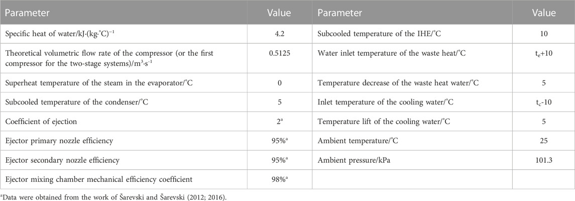
To analyze the safety, energy, and exergy performance of the aforementioned WV-HTHP systems, some parameters including discharge superheat, power consumption, heating capacity, COP, and exergy efficiency are compared under different working conditions. In the simulation, the condensation temperature is varied from 110°C to 190°C with an evaporation temperature of 80°C. At 140°C condensation temperature condition, the evaporation temperature is varied from 70°C to 100°C. The main parameters in the simulation are shown in Table 1.
4.1 Discharge superheat
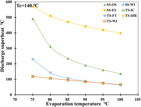
The discharge superheat indicates how much the actual exhaust temperature is higher than the saturation temperature at the compression process, which is an important index of safety performance. This is because high discharge temperatures will cause deformation of the rotors and housings, which will threaten the long-term security and stability of systems. Figures 8, 9 show the superheat of discharge steam for all systems under different condensation and evaporation temperature conditions, respectively.
Figure 8 presents that at a constant evaporation temperature, with an increase in condensation temperature, discharge superheat increases for all systems. This is because the discharge superheat has a positive correlation with compression ratio and a negative correlation with isentropic efficiency. With the increase in condensation temperature, the compression ratio augmentation and the isentropic efficiency reduction lead to the increase in discharge temperature. In addition, as the condensation temperature increases, the superheat of discharge steam for single-stage systems increases dramatically, which also results from the dramatic decrease in isentropic efficiency. For different single-stage systems, the superheat of discharge steam is disparate. However, it is almost the same as each other among two-stage systems. When the condensation temperature is not too high, the SS-ES has the highest discharge superheat followed by the SS-OS, and the SS-WI has a higher discharge superheat compared to two-stage systems. For instance, when the condensation temperature is 140°C, the discharge superheat is 509.7°C for the SS-ES, 311.4°C for the SS-OS, 143.2°C for the SS-WI, and 106.2°C for all two-stage systems. The results indicate that water injection and intercooling are both efficient ways to decrease discharge superheat. For two-stage systems with complete middle cooling, the suction state of the second compressor is a saturation state at middle pressure, which leads to the same discharge superheat. For the SS-ES, after being ejected by high-pressure saturation steam, the evaporation steam enters a superheated state with higher pressure at the suction side of the compressor. Although its compression ratio is smaller, the suction superheat leads to its excessive discharge superheat at a lower condensation temperature. This is also why the superheat temperature of the steam in the evaporator is set at 0°C in Table 1. However, as condensation temperature increases, the isentropic efficiency of the SS-OS and SS-WI decreases faster than that of the SS-ES. So, compared with the SS-OS and SS-WI, the SS-ES with smaller compression ratios and better isentropic efficiency has lower discharge superheat at higher condensation temperatures.
Figure 9 shows that at a constant 140°C condensation temperature, with an increase in evaporation temperature, the discharge superheat of all systems decreases, which is mainly due to the reduction of the compression ratio. Among different systems, the SS-ES with a higher suction temperature has the highest discharge superheat, followed by the SS-OS and SS-WI. Compared with single-stage compression systems, two-stage compression systems have the same discharge superheat with lower values at lower evaporation temperatures. This is due to their smaller compression ratios and higher system isentropic efficiencies.
4.2 Power consumption
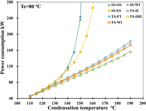
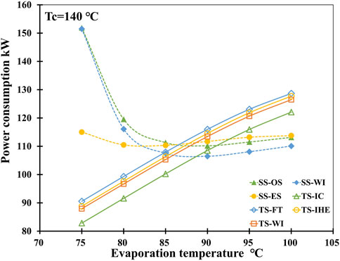
Power consumption is an important parameter to evaluate a heat pump system. In this section, the power consumption of those systems is analyzed. Figures 10, 11 illustrate the change in power consumption at different condensation and evaporation temperatures.
As shown in Figure 10, when the evaporation temperature is constant at 80°C, the power consumption increases versus the condensation temperature increases. Based on Eq. 4, this is mainly because of the enthalpy difference augment and isentropic efficiency degradation during the compression process, as the condensation temperature increases. Among different systems, the SS-OS consumes the largest power, followed by the SS-WI, SS-ES, TS-FT, TS-IHE, TS-WI, and TS-IC at lower condensation temperatures. For instance, at 140°C condensation temperature, the power consumption is 119.5 kW for the SS-OS, 116.1 kW for the SS-WI, 110.5 kW for the SS-ES, 91.5 kW for the TS-FT, 90.2 kW for the TS-IHE, 89.3 kW for the TS-WI, and 84.9 kW for the TS-IC. This phenomenon is decided by the mass flow rate and the compressor efficiencies, especially the isentropic efficiency. At lower condensation temperatures with similar isentropic efficiencies of all the systems, the mass flow rate determines the power consumption. When the condensation temperature is higher, the isentropic efficiency of single-stage systems decreases rapidly and has a great impact on power consumption. For the SS-ES, its higher suction pressure and smaller compression ratio lead to better isentropic efficiency compared to other single-stage systems, which determines its lower power consumption at higher condensation temperatures.
Figure 11 illustrates that at a constant condensation temperature, the power consumption of all single-stage systems has a minimum value with the increase in evaporation temperature. However, for two-stage systems, the power consumption increases versus the evaporation temperature. This is because for single-stage systems, the isentropic efficiency and the mass flow rate determine the power consumption at lower and higher evaporation temperatures, respectively. For example, the SS-ES with higher isentropic efficiency has smaller power consumption compared to the SS-OS and SS-WI at lower evaporation temperatures. At higher evaporation temperatures, the SS-ES with a larger mass flow rate has a larger power consumption compared to the SS-OS and SS-WI as the isentropic efficiency has little difference. For two-stage systems with the same isentropic efficiency, the mass flow rate determines the power consumption. With the same suction flow rate, the mass of the water refrigerant used to decrease the first compressor discharge temperature determines the mass flow rate. So, the TS-FT, which uses the most water refrigerant, has the most mass flow rate and power consumption, and the TS-IC, which uses an intercooler to realize, has the smallest power consumption.
4.3 Heating capacity
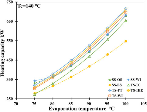
The heating capacity indicates the ability of a system to provide useful thermal energy, which is an important parameter for evaluating the energy performance of a heat pump. Figures 12, 13 present the heating capacity of these systems under different condensation and evaporation temperature conditions.
As shown in Figure 12, except for the TS-IC, the heating capacity for systems increases with the increase in condensation temperature. Based on Eq. 8 and Eq. 9, the heating capacity is determined by the mass flow rate and the enthalpy difference of the refrigerant at the heating side. For the TS-IC, the decrease in the mass flow rate determines its decreasing heating capacity. For other systems, the increase in the mass flow rate and enthalpy difference leads to an increase in the heating capacity. When the condensation temperature is 140 °C, the heating capacity is 378.6 kW for the TS-FT, 368.7 kW for the TS-IHE, 366.5 kW for the SS-WI, 362.1 kW for the SS-OS, 362.1 kW for the TS-WI, 358.3 kW for the TS-IC, and 315.8 kW for the SS-ES. Compared with the enthalpy difference, the mass flow rate is a more important factor at lower condensation temperatures. For single-stage systems, when the condensation temperature is high, the high discharge superheats also increase the enthalpy difference, which contributes to their heating capacity augment. However, for the SS-ES, one-third of its mass flow rate at the discharge side is used as driving steam to eject, so its heating capacity is the smallest.
Figure 13 presents that the heating capacity for all systems increases with the increase in evaporation temperature, which is determined by the mass flow rate. Among different systems, compared with the enthalpy difference at the heating sides, the mass flow rate plays a more important role in determining the heating capacity, especially for two-stage systems. Between the SS-OS and SS-WI, the SS-OS has a larger enthalpy difference and the SS-WI has a larger mass flow rate, so their heating capacities are similar. For the SS-ES, the separation of the water refrigerant at the heating side also leads to its smallest heating capacity.
4.4 COP
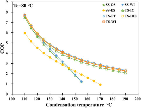
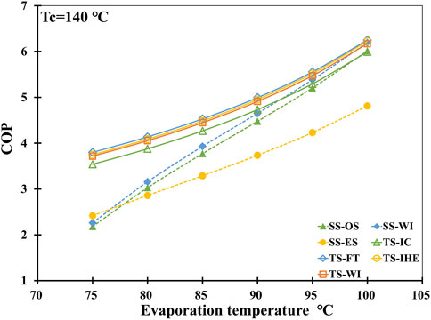
As the most important parameter to assess the energy performance of heat pump systems, the COP of these systems under different condensation and evaporation temperature conditions is analyzed and compared in Figures 14, 15, respectively.
Figure 14 illustrates that the COP of all systems has a negative correction with the condensation temperature. This means that power consumption increases faster than heating capacity with the increase in condensation temperature. Among different systems, the TS-FT has the highest COP, followed by the TS-IHE, TS-WI, TS-IC, SS-WI, SS-OS, and SS-ES at lower condensation temperatures. When the condensation temperature is 140°C, the COP is 4.14 for the TS-FT, 4.09 for the TS-IHE, 4.05 for the TS-WI, 3.88 for the TS-IC, 3.16 for the SS-WI, 3.03 for the SS-OS, and 2.86 for the SS-ES. Compared with the SS-OS, the COP of the TS-FT has an increment of 6.4%. This phenomenon means that two-stage systems with smaller compression ratios and better compressor efficiencies for each stage achieve better performance. Furthermore, compared with intercooling, water injection is a better way to improve the performance of WV-HTHP systems. When using the water injection in the middle stage, more injected refrigerant responds to better system performance. In single-stage systems, water injection also can improve system performance. However, at higher condensation temperatures, the SS-ES shows better COP compared to the SS-WI and SS-OS. The ejector used to increase the suction pressure can effectively improve the performance of the SS-ES when the temperature lift is high.
As shown in Figure 15, at a constant condensation temperature, the COP of all the systems has a positive correction with evaporation temperature. It results from the power consumption increasing slower than the heating capacity with the increase in evaporation temperature. At higher evaporation temperatures, the TS-FT has the highest COP, followed by the TS-IHE, SS-WI, TS-WI, SS-OS, TS-IC, and SS-ES. However, at lower evaporation temperatures, the SS-ES has better COP compared to the SS-WI and SS-OS. This is because the ejector shows better performance compared to the compressor with a higher temperature lift and a bigger compression ratio.
4.5 Exergy efficiency
Exergy efficiency is an important indicator to evaluate the potential of the thermodynamic quality of a heat pump system. Compared to conventional energy analysis, exergy analysis can quantitatively characterize the thermodynamic imperfection of the heat transfer process and the possibility for thermodynamic development.
The exergy efficiency for different WV-HTHP systems has similar characteristics to the COP. It decreases versus the condensation temperature increases at a constant evaporation temperature, and it increases versus the increase in evaporation temperature at a constant condensation temperature. This means that with the increase in condensation temperature and temperature lift, the exergy loss in systems increases. With the evaporation temperature augment and the temperature lift reduction, the exergy loss in those systems decreases. When the evaporation temperature is 80°C, the exergy efficiency for these WV-HTHP systems at 120°C, 140°C, and 160 °C condensation temperature is shown in Table 2. At a condensation temperature of 140°C, the exergy efficiency ranges from 57.4% to 70.9% for these systems, and the TS-FT has the best exergy efficiency, followed by the TS-IHE, TS-WI, SS-WI, SS-OS, TS-IC, and SS-ES. The exergy efficiency of the TS-FT is 19.8% higher than that of the SS-OS. This is because better compressor efficiencies lead to less exergy loss.

TABLE 2. Exergy efficiency with various condensation temperatures at an evaporation temperature of 80°C.
5 Conclusion
Based on the system configuration of WV-HTHP systems, six kinds of systems including two single-stage systems (SS-ES and SS-WI) and four two-stage systems (TS-IC, TS-IHE, TS-WI, and TS-FT) were analyzed and compared theoretically with the SS-OS as baseline. The efficiencies of the twin-screw compressor including the isentropic and volumetric efficiencies have a great influence on system performance. When the compression ratio is too high, the dramatic decrease in compressor efficiencies leads to the speedy degradation of system performance, especially for single-stage systems. So, this paper focuses on the high-temperature water vapor with a twin-screw compressor. When different compressors with different efficiency performances are used in the systems, the simulation results will be different too.
In addition, the two-stage compression system can supply a higher output temperature and have a better performance compared to the single-stage systems at the large temperature lift and high-compression ratio conditions. The water injection and intercooling methods are both efficient ways to decrease the superheat of discharge steam to keep the safety performance of these WV-HTHP systems. For two-stage compression systems, the TS-FT has the biggest heating capacity, the best COP, and the best exergy efficiency, which results from its bigger mass flow rate. So, compared with intercooling, water injection is a better choice to improve the energy and exergy performances of WV-HTHP systems. For single-stage systems, the ST-WI has better performance compared to the SS-OS in almost all aspects. It has a smaller discharge superheat temperature, which is like the two-stage systems. It also has a higher heating capacity with smaller power consumption, which results in better COP and exergy efficiency. However, the SS-ES has better COP and exergy efficiency compared to the SS-WI and SS-OS at large temperature lift and high-compression ratio conditions.
At an evaporation temperature of 80°C and condensation temperature of 140°C, the COP is 4.14 for the TS-FT. Compared with the SS-OS, the TS-FT has an increment of 36.6% in system COP. Meanwhile, the exergy efficiency is 70.9% for the TS-FT. The exergy efficiency of the TS-FT is 19.8% higher than that of the SS-OS. This means that the advantages of the TS-FT in COP and exergy efficiency are clear. Based on the aforementioned simulation results and analysis, the TS-FT is the optimal WV-HTHP system for high-temperature applications with the best safety, energy, and exergy performance.
Data availability statement
The raw data supporting the conclusion of this article will be made available by the authors, without undue reservation.
Author contributions
DW: conceptualization, data curation, visualization, writing–original draft, writing–review and editing, investigation, and validation. BH: formal analysis, methodology, project administration, software, writing–review and editing, funding acquisition, resources, and supervision.
Funding
The authors declare financial support was received for the research, authorship, and/or publication of this article. This research was supported by the National Natural Science Foundation of China (52306019 and 52036004), the Natural Science Foundation of Shanghai (21ZR1429800), and the China Postdoctoral Science Foundation (BX2021175 and 2022M712040).
Acknowledgments
The authors gratefully acknowledge the financial support received from the Cooperation Project of SJTU and YNEPRI (YNKJXM20190087).
Conflict of interest
Authors DW and BH were employed by Shanghai Nuotong New Energy Technology Co., Ltd.
Publisher’s note
All claims expressed in this article are solely those of the authors and do not necessarily represent those of their affiliated organizations, or those of the publisher, the editors, and the reviewers. Any product that may be evaluated in this article, or claim that may be made by its manufacturer, is not guaranteed or endorsed by the publisher.
References
Arpagaus, C., Bless, F., Schiffmann, J., and Bertsch, S. S. (2016). Multi-temperature heat pumps - a literature review. Int. J. Refrig. 69, 437–465. doi:10.1016/j.ijrefrig.2016.05.014
Arpagaus, C., Bless, F., Uhlmann, M., Schiffmann, J., and Bertsch, S. S. (2018). High temperature heat pumps: market overview, state of the art, research status, refrigerants, and application potentials. Energy 152, 985–1010. doi:10.1016/j.energy.2018.03.166
Arpagaus, C., Kuster, R., Prinzing, M., Bless, F., Uhlmann, M., Elias, B., et al. (2019). “High temperature heat pump using HFO and HCFO refrigerants - system design and experimental results,” in Proceedings of the The 25th IIR International Congress of Refrigeration, Montreal, Canada, September, 2019.
Arpagaus, C., and Stefan, S. B. (2019). “Experimental results of HFO/HFCO refrigerants in a laboratory scale HTHP with up to 150 °C supply temperature,” in Proceedings of the 2nd Conference on High Temperature Heat Pumps, Copenhagen, Denmark, September, 2019.
Bamigbetan, O., Eikevik, T. M., Nekså, P., and Bantle, M. (2017). Review of vapour compression heat pumps for high temperature heating using natural working fluids. Int. J. Refrig. 80, 197–211. doi:10.1016/j.ijrefrig.2017.04.021
Bamigbetan, O., Eikevik, T. M., Nekså, P., Bantle, M., and Schlemminger, C. (2018). Theoretical analysis of suitable fluids for high temperature heat pumps up to 125 °C heat delivery. Int. J. Refrig. 92, 185–195. doi:10.1016/j.ijrefrig.2018.05.017
Calm, J. M. (2008). The next generation of refrigerants - historical review, considerations, and outlook. Int. J. Refrig. 31, 1123–1133. doi:10.1016/j.ijrefrig.2008.01.013
Calm, J. M., and Hourahan, G. C. (1999). Physical, safety, and environmental data for refrigerants. Heat. Pip. Air Cond. 71, 27–29.
Chamoun, M., Rulliere, R., Haberschill, P., and Berail, F. (2011). Water vapour as refrigerant for a new high temperature heat pump. Jpn. J. Radiological Technol. 49, 1879–1887.
Chamoun, M., Rulliere, R., Haberschill, P., and Francois Berail, J. (2012). Dynamic model of an industrial heat pump using water as refrigerant. Int. J. Refrig. 35, 1080–1091. doi:10.1016/j.ijrefrig.2011.12.007
Chamoun, M., Rulliere, R., Haberschill, P., and Peureux, J. L. (2014). Experimental and numerical investigations of a new high temperature heat pump for industrial heat recovery using water as refrigerant. Int. J. Refrig. 44, 177–188. doi:10.1016/j.ijrefrig.2014.04.019
Heath, E. A. (2017). Amendment to the Montreal Protocol on substances that deplete the ozone layer (Kigali amendment). Int. Leg. Mater. 56, 193–205. doi:10.1017/ilm.2016.2
Hu, B., Wu, Di, and Wang, R. Z. (2018). Water vapor compression and its various applications. Renew. Sustain. Energy Rev. 98, 92–107. doi:10.1016/j.rser.2018.08.050
Jiang, J., Hu, B., Wang, R. Z., Deng, Na, Cao, F., and Wang, C. C. (2022). A review and perspective on industry high-temperature heat pumps. Renew. Sustain. Energy Rev. 161, 112106. doi:10.1016/j.rser.2022.112106
Larminat, P. D., Arnou, D., Le Sausse, P., Clunet, F., and Peureux, J. L. (2014). “A high temperature heat pump uses water vapor as working fluid,” in Proceedings of the 11th IIR Gustav Lorentzen Conference on Natural Refrigerants, Hang Zhou, China, August, 2014.
Liu, C., Han, W., and Xue, X. (2022). Experimental investigation of a high-temperature heat pump for industrial steam production. Appl. Energy 312, 118719. doi:10.1016/j.apenergy.2022.118719
Liu, J., Li, Q., Wang, F., and Zhou, L. (2012). A new model of screw compressor for refrigeration system simulation. Int. J. Refrig. 35 (4), 861–870. doi:10.1016/j.ijrefrig.2012.01.016
Madsboell, H., Weel, M., and Kolstrup, A. (2014). “Development of a water vapor compressor for high temperature heat pump applications,” in Proceedings of the 11th IIR Gustav Lorentzen Conference on Natural Refrigerants, Hang Zhou, China, August, 2014.
Šarevski, M. N., and Šarevski, V. N. (2016). Characteristics of R718 refrigeration/heat pump systems with two-phase ejectors. Int. J. Refrig. 70, 13–32. doi:10.1016/j.ijrefrig.2016.07.007
Šarevski, V. N., and Šarevski, M. N. (2012). Energy efficiency of the thermocompression refrigerating and heat pump systems. Int. J. Refrig. 35, 1067–1079. doi:10.1016/j.ijrefrig.2011.12.002
Schlemminger, C., Eirik, S. S., Sverre, S. F., Bantle, M., Bamigbetan, O., and Neksa, P. (2019). “Performance of high temperature heat pump for simultaneous and efficient production of ice water and process heat,” in Proceedings of The 25th IIR International Congress of Refrigeration, Montreal, Canada, August, 2019.
Shen, J., Xing, Z., Zhang, K., He, Z., and Wang, X. (2016). Development of a water-injected twin-screw compressor for mechanical vapor compression desalination systems. Appl. Therm. Eng. 95, 125–135. doi:10.1016/j.applthermaleng.2015.11.057
Shen, J. B., He, Z. L., and Xing, Zi W. (2014). Design and performance analysis of high temperature heat pump using water-jet screw type steam compressor. Refrig. Air-Conditioning 14, 95–98.
Stosic, N. (2015). On heat transfer in screw compressors. Int. J. Heat Fluid Flow 51, 285–297. doi:10.1016/j.ijheatfluidflow.2014.10.026
Tian, Ya F., Shen, J. B., Wang, C., Xing, Zi W., and Wang, X. L. (2017). Modeling and performance study of a water-injected twin-screw water vapor compressor. Int. J. Refrig. 83, 75–87. doi:10.1016/j.ijrefrig.2017.04.008
Watanabe, C., Nakamura, T., Yamada, M., Yamada, T., Hattori, A., Aono, T., et al. (2019). “Experimental study on a water and air source high-temperature heat pump using a low GWP refrigerant,” in Proceedings of the 25th IIR International Congress of Refrigeration, Montreal, Canada, August, 2019.
Wu, Di, Hu, B., and Wang, R. Z. (2019a). “Theoretical and experimental investigation on a very high temperature heat pump with water refrigerant,” in Proceedings of The 25th IIR International Congress of Refrigeration, Montreal, Canada, August, 2019.
Wu, Di, Hu, B., and Wang, R. Z. (2021). Vapor compression heat pumps with pure Low-GWP refrigerants. Renew. Sustain. Energy Rev. 138, 110571. doi:10.1016/j.rser.2020.110571
Wu, Di, Hu, B., Wang, R. Z., Fan, H., and Wang, R. (2020b). The performance comparison of high temperature heat pump among R718 and other refrigerants. Renew. Energy 154, 715–722. doi:10.1016/j.renene.2020.03.034
Wu, Di, Hu, B., Yan, H., and Wang, R. Z. (2019b). Modeling and simulation on a water vapor high temperature heat pump system. Energy 168, 1063–1072. doi:10.1016/j.energy.2018.11.113
Wu, Di, Jiang, J., Hu, B., and Wang, R. Z. (2020a). Experimental investigation on the performance of a very high temperature heat pump with water refrigerant. Energy 190, 116427. doi:10.1016/j.energy.2019.116427
Xu, Z. Y., and Wang, R. Z. (2016). Absorption refrigeration cycles: categorized based on the cycle construction. Int. J. Refrig. 62, 114–136. doi:10.1016/j.ijrefrig.2015.10.007
Nomenclature
Keywords: high-temperature heat pump, natural refrigerant water, system configuration, performance analysis, performance comparison
Citation: Wu D and Hu B (2023) Performance analysis of water refrigerant heat pump with different configurations for high-temperature application. Front. Energy Res. 11:1257865. doi: 10.3389/fenrg.2023.1257865
Received: 13 July 2023; Accepted: 16 October 2023;
Published: 06 November 2023.
Edited by:
Oyeniyi Oyewunmi, University of Calgary, CanadaReviewed by:
Xueqiang Li, Tianjin University of Commerce, ChinaJierong Liang, MagnoTherm Solutions GmbH, Germany
Copyright © 2023 Wu and Hu. This is an open-access article distributed under the terms of the Creative Commons Attribution License (CC BY). The use, distribution or reproduction in other forums is permitted, provided the original author(s) and the copyright owner(s) are credited and that the original publication in this journal is cited, in accordance with accepted academic practice. No use, distribution or reproduction is permitted which does not comply with these terms.
*Correspondence: Bin Hu, aGIxMjIzQHNqdHUuZWR1LmNu
 Di Wu1,2
 Bin Hu