 Qingyun Liu
- Business School, YinChuan University of Energy, NingXia, China
Inverters are widely used in the military, industrial production and defense fields as current conversion devices that convert direct current to alternating current. If the inverter fails, it can cause damage to other equipment, resulting in financial losses and, in extreme cases, compromising the safety of users. In this study, by integrating neural networks, the input signals of inverters are quickly converted to Fourier spectrum amplitudes, and from fault signals (such as load phase voltage) to feature vectors. In order to realize automatic extraction and fault detection of inverters, an optimization method is used to determine the appropriate number of nodes in the hidden layer of complex neural networks. The ability to efficiently allocate limited computing, storage, and network resources to meet user demand for services; Continuously optimize quality of service (QoS), including reducing latency, improving bandwidth, and increasing reliability. These problems directly affect the performance and user experience of MEC systems. By studying these issues and proposing corresponding solutions, we aim to improve the performance of MEC systems and provide higher quality services. The accuracy of defect diagnosis can reach higher than 99%, and the method has a high remission rate, demonstrating its effectiveness and benefits.
1 Introduction
Inverter failure should be given high priority because it may result in damage to the equipment and device, causing financial loss, and, in severe cases, endangering personal safety. It is crucial to perform fault diagnosis on inverters because they are widely used in national defence, military, and industrial production as current conversion devices to convert DC to AC. (Shang et al., 2021; Liu et al., 2020), although it appears to be a burden for coordinate transformation and other qualities, may efficiently diagnose errors. The fault diagnostic method is executed in accordance with the model created by the literature (Xu et al., 2019) and others, but it is necessary to create a precise mathematical model since failure to do so will have an impact on the fault identification outcomes. The performance of the inverter directly affects the following aspects: Energy conversion efficiency: When the inverter converts direct current to alternating current, there will be a certain amount of energy loss. Efficient inverters are able to minimize energy loss and convert more DC energy into useful AC energy. Therefore, the energy conversion efficiency of the inverter directly affects the overall efficiency of the system. Efficient inverters can provide more power supply, reduce energy waste, and reduce energy costs for users.
The output voltage and frequency stability of the inverter is very important for the connected load equipment. The stable output voltage and frequency ensure the normal operation of the load equipment and avoid damage or performance degradation. The failure of the inverter may cause fluctuations in the output voltage and frequency, which affects the normal operation of the load device. For example, voltage fluctuations can cause electronic devices to not work properly or even be damaged. Current quality: The current quality of the inverter refers to the ripple and harmonic content of the inverter output current. High quality current can reduce interference and damage to load equipment. Inverter failure may lead to an increase in current ripple and harmonics, which affects the normal operation of the load device. For example, harmonic currents can lead to increased motor noise and vibration, reducing equipment life. The importance of resolving inverter failures to ensure optimal system operation is to maintain the performance and reliability of the inverter. The failure of the inverter may cause the energy conversion efficiency to decrease, the output voltage and frequency to fluctuate, and the current quality to deteriorate, which will affect the normal operation of the load equipment and the overall performance of the system. Therefore, timely diagnosis and solution of inverter failure is very important. Through fault diagnosis, you can determine the type and location of the fault, and take appropriate repair measures. Timely repair of faults can restore the performance and reliability of the inverter and ensure the optimal operation of the system.
In addition, preventive maintenance and monitoring are also important means to solve the inverter failure. Regular inverter inspection and maintenance can prevent potential failures and ensure the long-term stable operation of the system. Real-time monitoring of inverter performance parameters and fault indicators can find and solve problems in time, improve the reliability and security of the system.
In short, resolving inverter failures to ensure optimal system operation is critical to maintaining inverter performance and reliability. The performance of inverter directly affects the energy conversion efficiency, output voltage and frequency stability, current quality and so on. Through fault diagnosis, timely repair, preventive maintenance and monitoring, the efficiency, stability and reliability of the inverter system can be improved to ensure the normal operation of the load equipment.
Compound failure refers to the situation where multiple failures occur at the same time, which can cause serious impact on inverter performance. Here are some common compound failures and the impact they can have on inverter performance: Input voltage fault and output current fault: Input voltage fault may cause the inverter to fail to work properly, and output current fault may cause the output power of the inverter to decrease. When these two failures occur at the same time, the inverter may completely lose power output. Fault current and temperature failure: Fault current can cause overload and damage to the internal components of the inverter, while temperature failure can cause the inverter to overheat. When these two faults occur at the same time, the inverter may face a greater risk of damage and may lead to serious safety problems such as short circuit or fire. Fault voltage and communication failure: The fault voltage may cause the inverter output voltage to be abnormal, and the communication failure may cause the inverter to be unable to communicate with the monitoring system. When these two faults occur at the same time, the inverter may not be able to report the fault information in a timely manner, resulting in the fault cannot be resolved in a timely manner.
The challenges faced by traditional diagnostic techniques mainly include the following aspects: Compound fault diagnosis: The traditional diagnostic technology can only diagnose a single fault, and the diagnostic ability of compound fault is limited. The interaction and influence of multiple faults need to be considered in the diagnosis of complex faults, which is a challenge for traditional diagnosis techniques. Fault feature extraction: Traditional diagnostic techniques often rely on manual fault feature extraction, which requires specialized knowledge and experience. However, compound faults may lead to changes in multiple fault features, which may increase the complexity of feature extraction. Data volume and complexity: Inverter systems typically generate a large amount of data, including sensor data, operation logs, and so on. Traditional diagnostic techniques may not be able to handle large-scale data and complex data structures, which may lead to poor diagnostic results. Real-time and reliability: Inverter systems often require real-time fault diagnosis, as well as timely measures to avoid further losses and risks. However, traditional diagnostic techniques may not be able to meet the requirements of real-time and reliability, which may lead to failures not being resolved in time. To sum up, the impact of compound faults on the performance of inverters may be very serious, and the traditional diagnostic techniques are faced with challenges in compound fault diagnosis, feature extraction, data volume and complexity, real-time and reliability. Therefore, it is necessary to develop and apply model-based fault diagnosis methods to solve these challenges and improve the reliability and safety of inverter systems.
The idea of compound faults was first introduced in a 1971 study by Schertz, who claimed that redundant circuits cause compound failures to appear in large-scale digital circuits (Wu et al., 2022). Multiple faults of the same kind occurring simultaneously, multiple faults of the same type coming from distinct fault sources, multiple faults occurring in various subsystems of the system interacting to produce new fault characteristics are all examples of compound faults (W et al., 2021). The majority of complex faults occur in complex systems, which are typically made up of numerous subsystems, subsystems, etc. Each functional module interacts with the others to increase the system’s level of uncertainty, increasing the system’s size and complexity relative to general systems. Compound faults are created when multiple faults occur at once and the system exhibits various, erratic, and mutually connected characteristic parameter changes for each of them. Traditional diagnosis techniques are challenging to use, and the likelihood of misdiagnosis and misdiagnosis is high. These techniques cannot accurately locate the fault location or identify the fault type and seriously jeopardise the system’s safe operation because there is a vague correspondence between fault characteristics and fault categories (Xie et al., 2022a).
In the early research on composite fault diagnosis, power grids and complex circuits were the primary research objects. Researchers divided the complex power grid structure into multiple substructures and designed to diagnose each substructure’s faults separately, before diagnosing the faults of the entire network as composite faults (Wu et al., 2019). The structure, connections between components, and faults produced in the system all get increasingly complex as the system scales up in engineering practise. As a result, numerous novel theories and techniques for composite fault identification are put forth. The methods for diagnosing compound defects produced in various systems have been thoroughly investigated in both domestic and foreign literature (Chandr et al., 2018). The power generation system’s capacity efficiency and cost, as well as its availability and whole-life maintenance costs, are directly impacted by the inverter’s performance condition (Jena et al., 2022).
Inverter failure can lead to the following specific consequences, which reinforces the importance of resolving inverter failure: Equipment damage: The inverter is a key device that converts direct current to alternating current. If the inverter fails, it may cause the entire inverter system to fail to operate normally and even damage other related devices. For example, an inverter failure can cause the voltage to be too high or too low, which can damage the motor, transformer and other equipment connected to the inverter.
Economic losses: Inverter failures can lead to increased downtime and repair costs, resulting in economic losses. For example, in a solar inverter system, if the failure of the inverter causes the solar panels to not work properly, it will lead to energy loss and a reduction in power generation, which will affect power generation revenue.
Risk to personal safety: Inverter faults may pose a threat to personal safety. For example, in a wind power inverter system, if the inverter fails and the wind turbine cannot be stopped, it may pose a danger to maintenance personnel and the surrounding environment. In summary, inverter failures can lead to equipment damage, economic losses, and personal safety risks, and these consequences highlight the importance of resolving inverter failures. By timely detection and resolution of inverter failures, potential losses and risks can be reduced, and the reliability and safety of the inverter system can be improved.
In this paper, a compound fault diagnosis method of inverter based on compound neural network is proposed. This method combines multiple neural network models to more accurately diagnose the fault type and location of the inverter. Compared with traditional methods, this method has higher accuracy and robustness. In addition, I will highlight the practicability and extensibility of the method, as well as its potential applications in power systems.
2 Related work
According to a review of domestic and foreign literature, the current methods for diagnosing compound faults can be broadly divided into two categories, namely, qualitative analysis methods and quantitative analysis methods, as a result of the rapid advancement of fault diagnosis technology (Xie et al., 2023). In order to diagnose compound faults using quantitative analysis methods, there are primarily two approaches that combine analytical and data-driven models. The data-driven approach is a novel approach that combines knowledge-based and signal-based methods, and it has become a hot topic in recent years’ research on compound fault diagnosis (Palanisamy et al., 2021). As more branches of each class of methods have been created, the idea of compound fault diagnostic methods has become more complex (Fazai et al., 2019).
Compared with power grids and complex circuits, inverter systems have some special characteristics and requirements. For example, inverter systems often need to meet the requirements of high precision, high efficiency and high reliability. In addition, the inverter system also needs to consider the control and protection of multiple parameters such as voltage, current, frequency, and power factor. Therefore, while there are some similarities between power grid and inverter systems, such as the concept and diagnostic methods of compound faults, there are some differences in the specific application and implementation. The relevance of this study lies in the application of composite fault diagnosis methods in power grids and complex circuits to inverter systems, and the improvement and optimization for the special needs of inverter systems. Through this research, we hope to better understand the characteristics and effects of compound faults in inverter systems, develop and apply fault diagnosis methods suitable for inverter systems, and improve the reliability and safety of inverter systems. This will provide useful reference and guidance for the design, operation and maintenance of inverter system.
Utilising the historical data of the system to build a model, quantitative analysis examines how the parameters of the diagnostic item vary over time in order to assess the health of the objectives. The quantitative analysis fault diagnostic techniques typically use two types of data-driven and analytical models.
1) Analytical model-based method
To reflect the differences in the system after various types of faults occur and to detect and diagnose the faults in accordance, these diagnostic methods use an accurate analytical model of the system and construct residual signals by computing the observable input and output quantities of the system model (Alsubari et al., 2022).
Model-based fault diagnosis methods increase the contribution to fault diagnosis accuracy and system availability by selecting relevant features, training models, classifying prediction and discovering unknown fault modes. It can help achieve fast, accurate and reliable fault diagnosis in practical applications and minimize equipment damage, economic losses and personal safety risks.
2) Data-driven approach
Big data-based analysis techniques use measurement data for different system parameters, from which the characteristics of a composite fault are extracted through specific data processing techniques. This makes it possible to diagnose composite faults without being aware of the exact analytical model of the system. Data-driven compound defect diagnosis techniques can considerably increase the efficiency of diagnosis while reducing the amount of time required to construct system models for many systems in engineering practise. Machine learning, signal processing, information fusion, and multivariate statistics are the key categories of data-driven approaches. Figure 1 illustrates the many branches of data-driven composite defect diagnosis techniques.
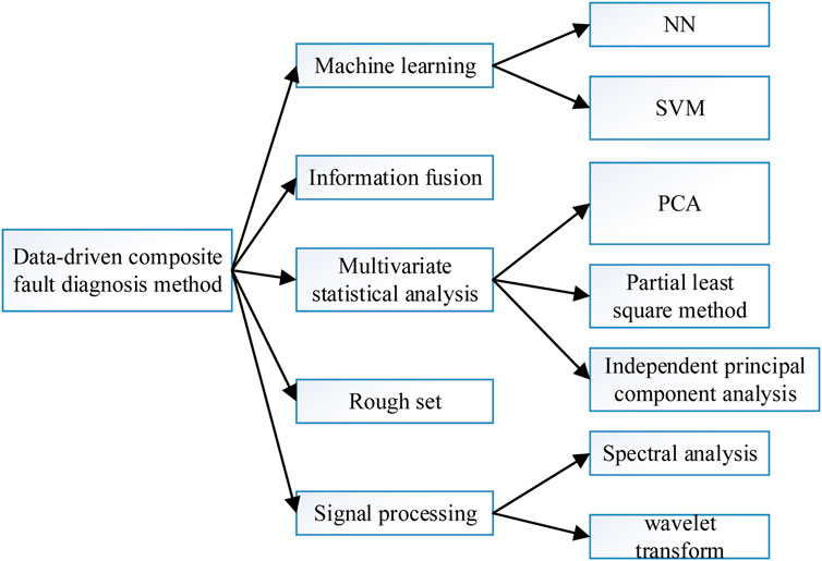
FIGURE 1. Data-driven composite fault diagnosis method.
The domestic study of composite fault identification is productive. (Liu et al., 2019). proposed a multiwavelet adaptive diagnosis method to extract fault features by redundantly decomposing the signal with cragginess as the optimisation objective. This method solved the diversity and strength imbalance problem of compound faults of mechanical equipment and was applied to the diagnosis of compound faults such as the outer and inner rings of rolling bearings of electric locomotives to verify; for the compound faults of rolling bearings of electric motors. With the advantages of an easy algorithm implementation, high accuracy, quick convergence, etc., (Bansode et al., 2016), proposed a particle swarm optimization-based blind source separation method that was successfully applied to the actual inner and outer ring composite fault blind source separation. In (Xie et al., 2022b), they proposed an online diagnosis method using the optimised composite neural network with L-M algorithm, and improved the accuracy of the composite neural network’s classifier by recursive least squares method to reduce the signal’s noise. They also used wavelet packet decomposition to amplify the fault features, which resolved the issue of it being difficult to separate the sensor faults after the occurrence of the composite fault (Abd et al., 2016; Al-Azab et al., 2022) achieved the separation and extraction of composite fault features for the composite faults of CNC machine tools by performing EEMD decomposition on the composite fault signal and single fault signal simultaneously, performing correlation analysis on each of their IMF components, and then decomposing the composite fault signal in accordance with the proportion of correlation coefficients. In order to achieve pattern recognition of various composite faults of CNC machine tools, (Alqahtani et al., 2022), used the KPCA method to reduce the dimensionality of the extracted features from the original composite signals. The composed kernel principal feature set was then used as the input of the GRNN network for training. Compound fault diagnostic techniques are the subject of numerous overseas studies as well. In (Pan et al., 2022), features were extracted from fault data with varying severity of multiple components for vehicle engine start system compound faults. Separate classifiers were then trained using regular polynomial regression, and finally the classifiers were combined by an integrated approach to construct a fault diagnosis framework, diagnosing compound faults and also predicting the severity of the fault, solving the issue of a strong correlation of fault characteristics of engine characteristics (Ali et al., 2015). In their analysis of gearbox problem diagnosis techniques, (Xie et al., 2021), suggested a hybrid model integrating a case-based inference classifier and an artificial immune system. Innovatively, (Cheng et al., 2020), realised fault diagnosis of gearboxes under various operating conditions by extracting features from the extended spectrum to perform automatic fault detection, localization, and separation. This was done in addition to the current signal order spectrum coherence. (Tang et al., 2020). developed a hybrid approach combining qualitative models and quantitative data that is targeted at the dynamic PLS system for compound defect identification.
In order to solve this problem, the optimization method is used to determine the appropriate number of nodes in the hidden layer of complex neural networks, and it is applied to automatic extraction and fault detection of inverters. By rapidly changing the amplitude of the Fourier spectrum of the fault signal, such as the load phase voltage, it is converted into a feature vector that serves as the input to the neural network. The experimental results show that the defect diagnosis accuracy of this method can reach more than 99%, and has a high remission rate, which proves its effectiveness and benefits.
3 Composite neural network
The popular circuit topology for three-phase voltage inverters in different sectors is shown in Figure 2. Complex neural networks are effective in automatically classifying models and extracting characteristics. However, as demonstrated in Figure 3, their grid categorization is sensitive to factors. The voltage between N and the load midpoint is the load phase voltage (
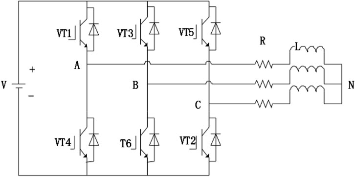
FIGURE 2. Three-phase voltage-type PWM inverter circuit.
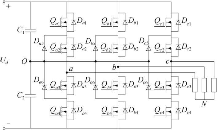
FIGURE 3. Schematic diagram of inverter structure.
Where,
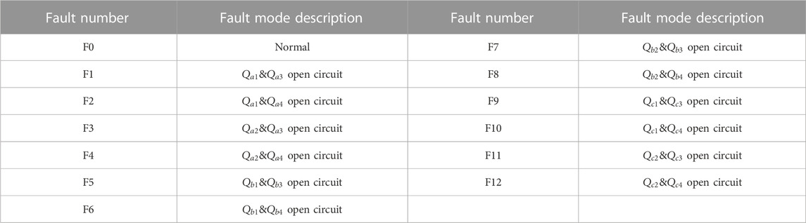
TABLE 1. NPC-type three-level inverter compound fault mode type.
3.1 Bat optimization algorithm (BOA)
The BOA is a brand-new population-based heuristic stochastic search algorithm, and its central idea is to use the biological mechanism of bats’ ultrasonic prey hunting (Bansode et al., 2016). Each bat in the BOA algorithm is comparable to a workable solution in the current search space. Suppose the dimension of the search space is
The present optimal solution is randomly perturbed when the bat search process is a local search, and a new local solution is produced by each bat wandering at random and may be expressed as:
where
The bat’s acoustic loudness and emission rate alter continuously during the iterative search, and once a prey item is located, the bat’s acoustic loudness decreases and its emission frequency rises. The bat’s sound volume and emission rate are updated in the manner described below:
Where
3.2 DBN modeling
The composite algorithm can be optimized by combining a DBN model with a multi-layer RBM as the main model. The RBM model, shown in Figure 4, consists of a visible layer consisting of all visible units
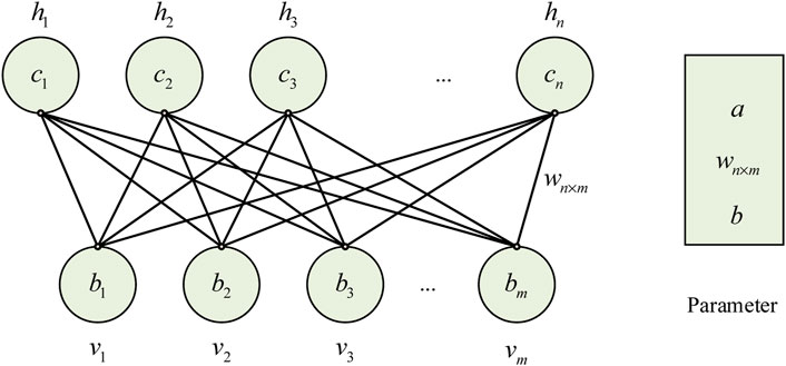
FIGURE 4. Schematic diagram of RBM.
The parameters of the RBM include the weight matrix
The three entirely related layers in the CNN model are replaced by a three-layer RBM. Prior to creating the learning parameters for directing the synthesis method, RBM is actually inserted without being controlled by the RBM preparation procedure. Figure 5 illustrates the parameter adjustment process, in which the DBN model starts the RBM learning process with the unnoticed image without supervision, trains the first level of RBM to the appropriate hidden layer, applies the activation probability of the hidden layer module to the second level of RBM without first training the second level of RBM, and then locally modifies the model parameters using the marked data and the synthesis algorithm.
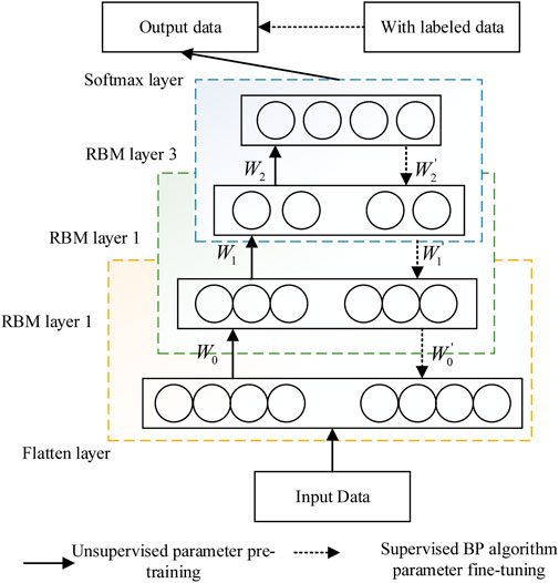
FIGURE 5. Training process for DBN parameter.
3.3 Parameter training of the composite neural network model
The preparation of CNN control parameters, the unsupervised preparation of RBM level, and the controllable adjustment of DBN parameters are the three stages of parameter preparation for the neural network synthesis model that correspond to the simulation process (Krishna et al., 2022). In particular, the forward and back propagation processes, as well as the preparation process of the monitored CNN parameters, are consistent with those of the first CNN model parameters (Krishna et al., 2023). The fully linked CNN layer is replaced with the DBN model without the RBM layer being preprocessed. The experimental parameters of the neural network comprehensive model are designed along with the reservoir parameters obtained from CNN parameter observation and training, and then the combination algorithm is used to perform a priori correction through the controllable adjustment process of DBN parameters.
The paper uses the nonlinear Relu function as neurons in each layer of the CNN model, denoted by
The forward propagation process of DBN model is the same as that of CNN except for the softmax layer, the cost function Q is the cross-entropy function, and the training goal is to minimize the cost function, the computation process and cost function of softmax layer are
4 Results and discussion
13 failure modes yield a total of 1300 fault characteristics. The amplitude spectrum obtained by FFT when the a-phase bridge arm power switch tube malfunctions is depicted in Figure 6. Before each load stage, 500 matching spectral component forces are intercepted, analysed, and overlapped to create a 1500-dimensional fault vector, and the number of hidden layer nodes is determined using the boa optimisation algorithm. This makes it easier to automatically extract the depth characteristics of the DBN network.
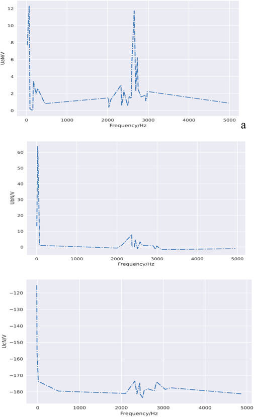
FIGURE 6.
The error profiles for further testing of the composite NN training are shown in Figure 7 and Figure 8. In this study, we use a composite neural network for inverter fault diagnosis and automatic extraction. In order to evaluate the performance of the network and the effect of the training process, we analyzed the error curve of the test phase in detail, as shown in Figure 7. Figure 7 shows how the loss function changes during training. It can be observed from the figure that in the initial stage, the value of the loss function is higher, which is caused by the random initialization of the initial weights of the network. With the progress of training, the loss function gradually decreases, indicating that the network gradually improves the accuracy of the prediction during the learning process. In the later stages of training, the rate of decline of the loss function slows down because the network is close to convergence and further optimization becomes more difficult. In addition, we also analyzed the error curve of the validation phase, as shown in Figure 8. The figure shows how the value of the loss function on the verification set changes with the number of training iterations. It can be observed from the figure that the loss function value on the verification set gradually decreases during the training process, indicating that the generalization ability of the network is constantly improving. However, if overfitting occurs during training, the value of the loss function on the validation set may begin to rise. Therefore, in practical applications, we need to monitor the error curve on the verification set to determine if the network is overfitting or underfitting, and adjust the structure or training strategy of the network accordingly.
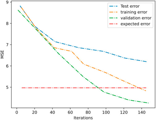
FIGURE 7. Composite NN training error curve.
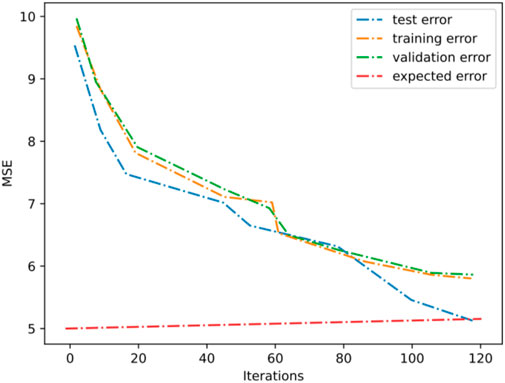
FIGURE 8. Training error of the improved complex neural network.
Through the detailed analysis of the error curve of the test stage, we can evaluate the training effect of the composite neural network, and make a reasonable explanation and verification of its performance. This helps us to further optimize the network structure and training strategy for more accurate and reliable inverter fault diagnosis and automatic extraction.
As seen in Figure 7, when the complex neural network has undergone approximately 125 iterations, the global MSE of the training samples approaches the expected error value. However, the error curves of the test and validation samples deviate from the expected error, and the overall classification effect is subpar. As seen in Figure 8, the composite neural network improved by the momentum factor and iteration step self-adjustment method converges after roughly 100 iterations, and the learning rate of the network is significantly improved. The error curves of the validation and test samples are close to the expected error and show a stable trend, indicating that the improved complex neural network’s classification effect has been improved. Fifty sets of data for each of the three failure modes were collected and tested using a modified composite neural network classifier.
With a few instances of misinterpretation for single and composite fault data, Table 2 shows that the upgraded composite neural network obtains an overall right diagnosis rate of over 95% for no fault, single fault with U-phase sensor bias, and composite fault with U/V two-phase sensor bias. The efficiency of the composite defect diagnosis algorithm has been experimentally verified.

TABLE 2. Diagnostic results of the improved composite neural network classifier.
The classic integrated neural network and SVM diagnosis methods are contrasted, and each complex fault of the three-stage inverter is diagnosed in accordance with the accuracy depicted in Table 3 and Figure 9 to confirm the efficacy and viability of the suggested method. In inverter systems, neural networks can be integrated and put into play by following steps:
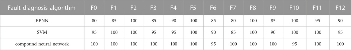
TABLE 3. Classification accuracy of each compound fault mode of inverter %.
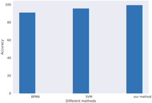
FIGURE 9. Comparison of results using different fault diagnosis algorithms.
Data collection: First of all, the normal operation data and fault data of the inverter system need to be collected. These data can include sensor readings, current, voltage, temperature and other parameters.
Data preprocessing: Data needs to be preprocessed before it is fed into the neural network. This may include steps such as data cleaning, de-noising, normalization, etc., to ensure data accuracy and consistency.
Feature extraction: Next, the neural network can automatically extract features related to the fault by learning a large amount of data. These features can be statistical features of sensor readings, spectral features, etc.
Model training: Once the features are extracted, the labeled fault data can be used to train the neural network model. Through iterative training, the neural network can learn the difference between failure mode and normal operation mode.
Fault detection: After the training is completed, new data can be input into the trained neural network model for fault detection. The neural network will determine whether there is a fault according to the characteristics of the input data and the previously learned pattern, and output the corresponding fault type or abnormal situation. In the inverter system, the specific role of neural network is to realize fault detection and diagnosis. It can automatically extract features from sensor data and learn to identify fault patterns. In this way, operators can detect and resolve faults in a timely manner, improving system reliability and availability. At the same time, the neural network can also detect unknown failure modes, help find potential failures, and take appropriate measures to repair and repair.
Inverter composite fault classification accuracy utilising composite NN, SVM, and compound neural network is 90.77%, 95.38%, and 99.23%, respectively, according to Figure 9. As a result, the suggested compound neural network inverter’s comprehensive fault diagnosis accuracy is higher than that of the conventional comprehensive neural network and auxiliary vector machine. It can be challenging to accurately discern the fault type between the conventional recombinant NN and SVM since the fault nature may be identical. The in-depth features are further collected using the compound neural network in-depth research approach, and various fault types are precisely identified.
In addition to the metrics evaluated in the experiment, an integrated approach to resolving inverter failures can provide the following additional benefits: Improve the accuracy of fault diagnosis: By integrating the method of solving the inverter fault, the accuracy of fault diagnosis can be improved. The identification and solution of inverter faults can help the system diagnose and locate faults more accurately, and reduce the possibility of false positives and misdiagnosis. Improve the efficiency of fault diagnosis: Integrating the method of solving the inverter fault can also improve the efficiency of fault diagnosis. The feature extraction and fault diagnosis algorithm of inverter faults can quickly identify and locate faults, and reduce the time and cost of fault diagnosis. Improved system reliability: By integrating the method of solving inverter faults, the reliability of the system can be improved. Timely identification and resolution of inverter failures can reduce system downtime and production losses, and improve system availability and reliability. Reduced maintenance costs: Integrated solutions to inverter failures can also reduce maintenance costs. Through automatic fault repair mechanism and fault alarm notification mechanism, manual intervention and maintenance costs can be reduced. In summary, integrating the method to solve the inverter fault into the existing composite fault diagnosis system can improve the accuracy and efficiency of fault diagnosis, improve the reliability of the system, and reduce the maintenance cost. These additional benefits can further improve the performance and reliability of the system, providing a better user experience.
5 Conclusion
This paper classifies the performance flaws of the fault inverter, uses the advanced depth persuasion network to automatically extract the depth features, and uses a variety of complex regional faults to obtain the feature information. This is due to the difficulty in extracting the complex nature of the fault. The issue of choosing hidden layer nodes in a DBN network is also resolved by the concept of compound neural network diagnosis reorganisation. The experimental findings demonstrate the usefulness and viability of the diagnosis technique based on compound neural networks, which has higher fault certainty and higher classification degree than the conventional integrated NN and SVM. In future work, we will expand the scope of the experiment to include more fault situations and data sets to verify the applicability and robustness of the composite neural network in a wider range of scenarios. This will help further develop and advance fault diagnosis techniques based on composite neural networks and provide more accurate and reliable results.
Data availability statement
The original contributions presented in the study are included in the article/supplementary material, further inquiries can be directed to the corresponding author.
Author contributions
Study conception and design QL; data collection QL; analysis and interpretation of results QL; draft manuscript preparation QL.
Conflict of interest
The author declares that the research was conducted in the absence of any commercial or financial relationships that could be construed as a potential conflict of interest.
Publisher’s note
All claims expressed in this article are solely those of the authors and do not necessarily represent those of their affiliated organizations, or those of the publisher, the editors and the reviewers. Any product that may be evaluated in this article, or claim that may be made by its manufacturer, is not guaranteed or endorsed by the publisher.
References
Abd, Algalil, Fahd Mohammed, A., and Zambare, S. P. (2016). New species of flesh fly (Diptera: sarcophagidae) sarcophaga (liosarcophaga) geetai in india. J. Entomol. Zool. Stud. 4 (3), 314–318.
Al-Azab, A. M., Zaituon, A. A., Al-Ghamdi, K. M., and Al-Galil, F. M. A. (2022). Surveillance of dengue fever vector Aedes aegypti in different areas in Jeddah city Saudi Arabia. Adv. Anim. Vet. Sci. 10 (2), 348–353.
Ali, Rahman, Hameed Siddiqi, Muhammad, and Lee, Sungyoung (2015). Rough set-based approaches for discretization: A compact review. Artif. Intell. Rev. 44 (2), 235–263. doi:10.1007/s10462-014-9426-2
Alqahtani, Abdulaziz R., Badry, Ahmed, Sayed, A. M. Amer, Fahd, Mohammed, Abd, Al Galil, Mervat, A. Ahmed, et al. (2022). Intraspecific molecular variation among Androctonus crassicauda (Olivier, 1807) populations collected from different regions in Saudi Arabia. J. King Saud University-Science 34 (4), 101998. doi:10.1016/j.jksus.2022.101998,
Alsubari, S. N., Deshmukh, S. N., Alqarni, A. A., Alsharif, N., H. H. Aldhyani, T., Waselallah Alsaade, F., et al. (2022). Data analytics for the identification of fake reviews using supervised learning. CMC-Computers, Mater. Continua 70 (2), 3189–3204. doi:10.32604/cmc.2022.019625
Bansode, S. A., More, V. R., Zambare, S. P., and Fahd, M. (2016). Effect of constant temperature (20 0C, 25 0C, 30 0C, 35 0C, 40 0C) on the development of the Calliphorid fly of forensic importance, Chrysomya megacephala (Fabricus, 1794). J. Entomology Zoology Stud. 4 (3), 193–197.
Chandra, K., Marcano, A. S., Mumtaz, S., Prasad, R. V., and Christiansen, H. L. (2018). Unveiling capacity gains in ultradense networks: using mm-wave NOMA. IEEE Veh. Technol. Mag. 13 (2), 75–83. doi:10.1109/mvt.2018.2814822
Cheng, Y., Dong, W., Gao, F., and Xin, G. (2020). Open-circuit fault diagnosis of traction inverter based on compressed sensing theory. Chin. J. Electr. Eng. 6 (1), 52–60. doi:10.23919/cjee.2020.000004
Fazai, R., Abodayeh, K., Mansouri, M., Trabelsi, M., Nounou, H., Nounou, M., et al. (2019). Machine learning-based statistical testing hypothesis for fault detection in photovoltaic systems. Sol. Energy 190, 405–413. doi:10.1016/j.solener.2019.08.032
Jena, S., Paladhi, S., and Pradhan, A. K. (2022). Bus protection in systems with inverter interfaced renewables using composite sequence currents. Int. J. Electr. Power and Energy Syst. 136, 107665. doi:10.1016/j.ijepes.2021.107665
Krishna, V. M., Sandeep, V., Murthy, S. S., and Yadlapati, K. (2022). Experimental investigation on performance comparison of self excited induction generator and permanent magnet synchronous generator for small scale renewable energy applications. Renew. Energy 195, 431–441. doi:10.1016/j.renene.2022.06.051
Krishna, V. M., Sandeep, V., Narendra, B. K., and Prasad, K. R. K. V. (2023). Experimental study on self-excited induction generator for small-scale isolated rural electricity applications. Results Eng. 18, 101182. doi:10.1016/j.rineng.2023.101182
Liu, Qingfeng, Liu, Chenxuan, and Wang, Yanan (2019). etc. Integrating external dictionary knowledge in conference scenarios the field of personalized machine translation method. J. Chin. Inf. 33 (10), 31–37.
Liu, S., Xie, J., Shen, C., Shang, X., Wang, D., and Zhu, Z. (2020). Bearing Fault diagnosis based on improved convolutional deep belief network. Appl. Sci. 10 (18), 6359. doi:10.3390/app10186359
Palanisamy, S., Thangaraju, B., Khalaf, O. I., Alotaibi, Y., Alghamdi, S., and Alassery, F. (2021). A novel approach of design and analysis of a hexagonal fractal antenna array (HFAA) for next-generation wireless communication. Energies 14, 6204. doi:10.3390/en14196204
Pan, X., Lin, H., Han, C., Feng, Z., Wang, Y., Lin, J., et al. (2022). Computerized tumor-infiltrating lymphocytes density score predicts survival of patients with resectable lung adenocarcinoma. Iscience 25 (12), 105605. doi:10.1016/j.isci.2022.105605
Pidikiti, T., Gireesha, B., Subbarao, M., and Krishna, V. M. (2023). Design and control of Takagi-Sugeno-Kang fuzzy based inverter for power quality improvement in grid-tied PV systems. Meas. Sensors 25, 100638. doi:10.1016/j.measen.2022.100638
Saghezchi, Firooz B., Radwan, Ayman, Rodriguez, Jonathan, and Dagiuklas, Tasos (2013). Coalition formation game toward green mobile terminals in heterogeneous wireless networks. IEEE Wirel. Commun. 20 (5), 85–91. doi:10.1109/mwc.2013.6664478
Shang, Z., Li, W., Gao, M., Liu, X., and Yu, Y. (2021). An intelligent fault diagnosis method of multi-scale deep feature fusion using information entropy. Chin. J. Mech. Eng. 34 (1), 1–16.
Tang, G., Wang, Y., Huang, Y., Liu, N., and He, J. (2020). Compound bearing fault detection under varying speed conditions with virtual multichannel signals in angle domain. IEEE Trans. Instrum. Meas. 69 (8), 5535–5545. doi:10.1109/tim.2020.2965634
Wang, Z., Zhao, W., Du, W., Li, N., and Wang, J. (2021). Data-driven fault diagnosis method based on the conversion of erosion operation signals into images and convolutional neural network. Process Saf. Environ. Prot. 149, 591–601. doi:10.1016/j.psep.2021.03.016
Wu, C., Jiang, P., Ding, C., Feng, F., and Chen, T. (2019). Intelligent fault diagnosis of rotating machinery based on one-dimensional convolutional neural network. Comput. Industry 108, 53–61. doi:10.1016/j.compind.2018.12.001
Wu, Di, Yin, Lei, He, Maoen, Zhang, Chunjiong, and Ji, Li (2022). Deep reinforcement learning-based path control and optimization for unmanned ships. Wirel. Commun. Mob. Comput. 2022, 7135043. doi:10.1155/2022/7135043
Xie, X., Pan, X., Shao, F., Zhang, W., and An, J. (2022a). Mci-net: multi-scale context integrated network for liver ct image segmentation. Comput. Electr. Eng. 101, 108085. doi:10.1016/j.compeleceng.2022.108085
Xie, X., Pan, X., Zhang, W., and An, J. (2022b). A context hierarchical integrated network for medical image segmentation. Comput. Electr. Eng. 101, 108029. doi:10.1016/j.compeleceng.2022.108029
Xie, X., Zhang, W., Pan, X., Xie, L., Shao, F., Zhao, W., et al. (2023). Canet: context aware network with dual-stream pyramid for medical image segmentation. Biomed. Signal Process. Control 81, 104437. doi:10.1016/j.bspc.2022.104437
Xie, X., Zhang, W., Wang, H., Li, L., Feng, Z., Wang, Z., et al. (2021). Dynamic adaptive residual network for liver CT image segmentation. Comput. Electr. Eng. 91, 107024. doi:10.1016/j.compeleceng.2021.107024
Keywords: inverter, composite fault, composite neural network, fault diagnosis, automatic extraction
Citation: Liu Q (2023) Transformation of reverse marketing model for electrical appliances based on Markov chain optimization with information technology support. Front. Energy Res. 11:1249014. doi: 10.3389/fenrg.2023.1249014
Received: 28 June 2023; Accepted: 11 September 2023;
Published: 25 September 2023.
Edited by:
Praveen Kumar Donta, Vienna University of Technology, AustriaReviewed by:
Dipak Sah, GLA University, IndiaV. B. Murali Krishna, National Institute of Technology, India
Copyright © 2023 Liu. This is an open-access article distributed under the terms of the Creative Commons Attribution License (CC BY). The use, distribution or reproduction in other forums is permitted, provided the original author(s) and the copyright owner(s) are credited and that the original publication in this journal is cited, in accordance with accepted academic practice. No use, distribution or reproduction is permitted which does not comply with these terms.
*Correspondence: Qingyun Liu, cWluZ3l1bmwyMDIzQDE2My5jb20=