 Xiaoguang Kong*
 Yaowen Zhang
- School of Information Engineering, Shenyang University of Chemical Technology, Shenyang, China
As high-performance motors, permanent magnet motors are widely used in a wide range of applications. It has become a consensus to mine reluctance torque in permanent magnet motors. The combination of permanent magnet motors and reluctance motors to generate higher output torque is one of the hotspots in motor research. A dual-rotor motor can be formed by connecting a coaxial connector or a concentric end disk, which can make the motor generate higher torque. However, although the motor torque has been improved, the cogging torque still affects the output torque of the motor. This paper describes a method to reduce the cogging torque of the permanent magnet rotor of the permanent magnet-assisted double rotor motor. By analyzing the motor power equation, it is concluded that the pole arc coefficient, the thickness of the magnetic steel, the length of the air gap, and the slot width of the stator have four influences on the teeth. For the parameters of the slot torque, the upper and lower limits of the parameter value are obtained according to the size of the motor. A certain parameter is taken as a fixed value, and the remaining parameters are uniformly valued. Use parametric scanning to determine the optimal value range of the parameter, and use Maxwell for parameterization. Simulation and analysis show that the cogging torque of the motor is reduced by 90% and the torque ripple is reduced by 50%. In order to simplify the motor control system, this paper designs a fuzzy controller based on granular functions, and the fuzzy rules of the fuzzy controller are to perform feature sampling and fit the response function, eliminating fuzzification and defuzzification, improving the response speed of fuzzy control, and simplifying the control system.
1 Introduction
The advantages of permanent synchronous motors include their small size, light size, minimal loss, outstanding performance, and wide range of applications (Wang and Leng, 2018). They are widely used for various occasions and equipment. However, due to the high price and limited supply of rare earth magnets, the development of high-performance motors without rare earths has gradually attracted great attention. Reducing the use of permanent magnets in permanent magnet motors and using synchronous reluctance motors without permanent magnets are feasible alternatives. The synchronous reluctance motor has a reliable mechanical design, a low cost, and a multi-barrier construction that can efficiently enhance the output torque, but its applicability is also constrained by its drawbacks of poor torque density and low factor (Hofmann and Sanders, 2000).
The two ideal properties of a motor are high torque density and high efficiency (Agbo et al., 2021). Due to its high torque density and high space efficiency, the double-rotor motor has always been a research focus for scientists. In recent years, in order to further improve the motor efficiency and torque density, scientists from different countries have developed various types of double rotor motors, such as double rotor permanent magnet motors with different pole topologies (NS) (Qu and Lipo, 2003) and double rotor disc motors with modified stator core yoke (Liu and Li, 2022), steel sheets instead of part of the permanent magnets reduce the Manufacturing cost of the double rotor axial flux motor (Diao et al., 2023), and there is also a concentric switched double-rotor reluctance motor that integrates two rotors and two stators into a compact and robust structure (Aravind et al., 2011; Al-Ani, 2021), and a switched double-rotor reluctance motor with magnetic isolation ring (Shirzad, 2023), and yokeless double-rotor mutual coupling switched reluctance motor (Fu et al., 2023); magnetic field modulation brushless double-rotor machine (Bai et al., 2015), double-rotor in-wheel motor with multiple operating modes (Li et al., 2023) Permanent magnet reluctance dual rotor motor (Li et al., 2017), and so on. In general, it is mainly divided into permanent magnet double rotor motors and reluctance double rotor motors. In this paper, combining the advantages of a permanent magnet motor and a reluctance motor, a permanent magnet-assisted dual-rotor motor is proposed.
In order to achieve the goals of high torque density and wide constant-speed operating range, a permanent magnet assisted dual-rotor motor is proposed in this paper, which adopts a dual-rotor radial flux configuration, combining the synchronous reluctance rotor and the permanent magnet rotor with rare earth permanent magnets to form a single motor entity, the design can control reluctance torque and permanent magnet torque more flexibly, since the cogging torque determines the torque ripple, and the torque ripple affects the quality of the output torque, therefore the goal of the permanent magnet synchronous motorization of the outer rotor is to reduce the cogging torque, according to the definition of the cogging torque, determine the parameters that affect the cogging torque, such as the pole arc coefficient, considering that the parameters have little influence on each other, the parameter sweep method can be used. The range of parameter optimization is given according to the size constraints of the motor, and the cogging torque of the permanent magnet rotor is optimized. Through the simulation analysis of the optimized motor model, the effectiveness of this optimization scheme is verified. Finally, the permanent magnet-assisted dual-rotor motor designed in this paper has the characteristics of a magnetic isolation ring. The motor is split into internal and external parts for control. The internal and external motor control systems share a speed loop and are equipped with hysteresis controllers, respectively. The internal and external motors use torque ratios for current distribution and introduce granular functions to improve the constant fuzzy speed loop, which simplifies the control system and improves the rapidity and robustness of motor response.
2 Motor preliminary design
2.1 Motor topology
The outer rotor of a permanent magnet assisted dual rotor motor is a surface-mounted permanent rotor, which shares several characteristics with permanent magnet dual rotor motors. The distinction is that the permanent magnet synchronous motor and the synchronous reluctance motor are integrated into a single motor, and the synchronous reluctance rotor is used to replace the internal permanent magnet rotor (Yunyun et al., 2012). The two rotors share a shaft and rotate at the same mechanical speed. The stator winding adopts the ring winding method, and the magnetomotive force direction of the stator winding of the outer motor is opposite that of the stator winding of the inner motor. In order to achieve magnetic insulation between the inner stator and the outer stator, a magnetic insulator used as a barrier ring is used in the middle of the stator yoke. The insulator is made of brass. Figure 1 is a three-dimensional diagram of the motor. The parameters of the motor are shown in Table 1.
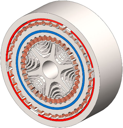
FIGURE 1. 3D model of motor.
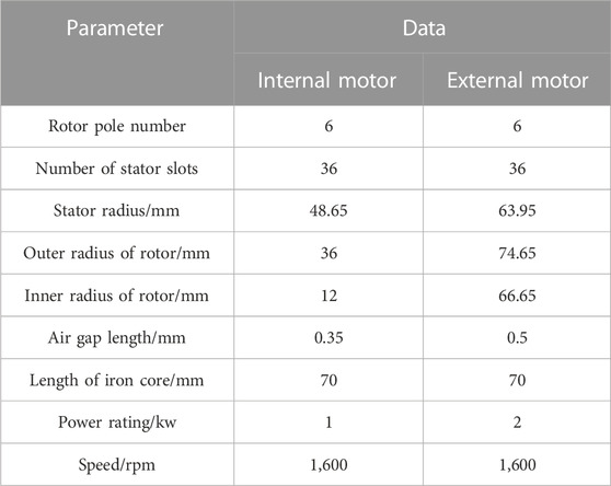
TABLE 1. Main parameters of the motor.
In order to ensure that the motor outputs ideal torque, the internal synchronous reluctance rotor should be properly designed. The typical number of rotor poles of a synchronous reluctance motor is four, but this requires the external surface-mounted permanent magnet rotor to also maintain a four-pole topology. This design method will cause the external permanent magnet rotor yoke to become thicker, and with added weight comes reduced performance. The external surface-mounted permanent magnet rotor is more suitable for the application of multi-rotor pole topology to reduce the thickness of the yoke and the weight of the motor, but this type of topology is not the best design for synchronous reluctance motors because, because of the multi-pole structure, the pole speed of the magnetization inductor of the synchronous reluctance rotor will decrease, and the performance of the synchronous reluctance rotor will also decrease under the condition of a high pole number. Therefore, the number of rotor poles selected for this type of motor is six, and the number of poles of the inner and outer rotors is the same, so as to balance the low number of magnetic poles of the synchronous reluctance rotor and the high number of magnetic poles of the surface-mounted permanent magnet rotor.
The design of the synchronous reluctance rotor flux barrier focuses on the number and position of each flux barrier layer. Generally, for the inner rotor synchronous reluctance motor, the torque ripple decreases with the increase of the number of flux barriers, but due to the limitations of the manufacturing process, the rotor flux barriers are generally set to 4 layers in the design of the synchronous reluctance motor (Jurca and Martis, 2017), so the number of rotor magnetic barriers in this paper is also set to 4 layers.
Different windings, cogging slots, permanent magnet arrangements, and reluctance rotor magnetic barrier shapes of permanent magnet-assisted dual-rotor motors have various topological structures. The permanent magnet rotor can not only be installed on the surface but also be buried in the ground, and the shape of the magnetic barrier of the reluctance rotor can also be LAL, ARC, segmented rectangle, etc. Figure 2 shows the permanent magnet rotor and a few examples of magnetic choke rotors.
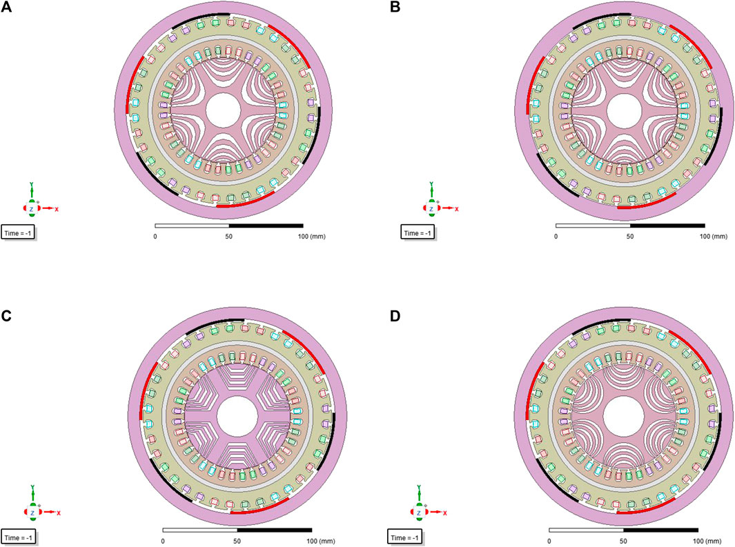
FIGURE 2. Other types of permanent magnet assisted reluctance dual-rotor motor topology: (A) Hyperbolic magnetic barrier, (B) Plug-in permanent magnet, (C) Segmented magnetic barrier, (D) ARC barrier.
2.2 Motor power equation
2.2.1 External permanent magnet motor
The rated output power of the motor is the product of the number of phases, voltage, and current of the motor. There must be conversion efficiency in power conversion, and the stator waveform of the motor is a rectangular wave rather than a sine wave in most cases. Therefore, it is necessary to multiply the motor efficiency coefficient
Among them,
The peak value of the back electromotive force of the external permanent magnet motor can be expressed as the product of the peak value of the air gap flux density, the effective length of the winding, and the speed at which the winding cuts the magnetic induction line,
Among them,
Use the electrical load value
Substituting parameters in Eqs 2, 3 into Eq. 1, the output power of the motor can be expressed as:
2.2.2 Internal reluctance motor
The stator winding must supply the d-axis and q-axis current components to generate the reluctance torque, so in the expression, the formula needs to be multiplied by an included angle coefficient
Among them,
2.2.3 Double rotor motor
By combining the constraint equations of the external permanent magnet motor and the internal reluctance motor, the complete constraint equation of the dual-rotor motor can be derived, the output power
Since the inner and outer motor stator windings of the motor are connected in series, the winding currents are equal, so it can be obtained:
A simple transformation can be obtained
The relationship between the load on the inner rotor side and the outer rotor side can be expressed by the ratio of the inner diameter of the inner motor to the outer diameter of the outer motor:
Putting Formula (9) into Formula (6), after simplification, motor total power
3 Cogging torque optimization
3.1 Cogging torque and optimization method
A major contributor to torque ripple in permanent magnet motors is the cogging torque (Wang et al., 2011). In order to reduce the influence of the cogging torque on the surface-mount permanent magnet motor, Patel (2023) recommended slotting to reduce the gear toque by 48.78%. Rashid and Mohammed (2023) proposed a sawtooth moment mitigation method based on the radial slits of the pole pieces. Won et al. (2023) used neural network prediction to achieve the purpose of reducing cogging torque. Wang et al. (2023) adopted the method of combining in-phase unit (IPU) grouping and slotting angle offset so that the main harmonic component of the sawtooth torque is cancelled to achieve the purpose of reducing the cogging torque.
This paper chooses to determine the factors affecting cogging torque from the definition of cogging torque. Cogging torque
In the formula,
In the formula,
In the formula,
3.2 Determine optimization variables and parameter ranges
It can be seen from the above formula that the slot opening angle width, magnetic steel angle width, magnetic steel thickness, and air gap length all have a great influence on the cogging torque. Therefore, these four parameters are selected as the cogging torque optimization parameters in this paper to study their effect on cogging torque. Table 2 lists the optimized variable parameter ranges.
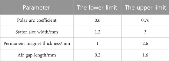
TABLE 2. Optimize the parameter range.
3.3 Parameter optimization
In order to explore the law of cogging torque weakening caused by different design variables, each design variable is parameterized in the optimization process, and one parameter is selected as a variable. The upper and lower limits are given as shown in Table 2. Other parameters are constants; after obtaining the waveforms of the cogging torque in various situations, select the maximum value to draw the trend of the cogging torque changing with the parameters, and select the optimal parameters for simulation verification in Maxwell. If the optimal effect meets expectations, the optimization is complete. If the effect is not as expected, it is necessary to change the upper and lower limits of the parameters or to optimize the parameters. The specific optimization scheme flow chart is shown in Figure 3. As we can see in Figure 4, the optimal values of the four parameters can be easily found according to the graph.
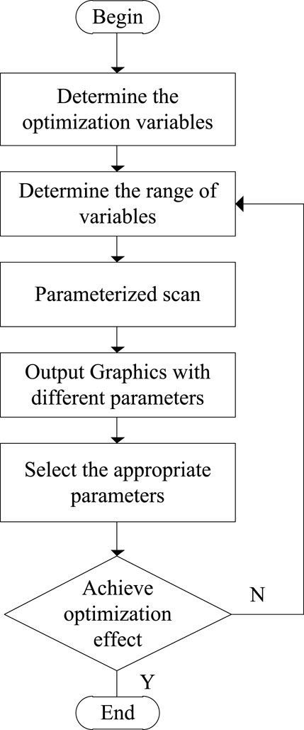
FIGURE 3. Flow chart of cogging torque optimization scheme.
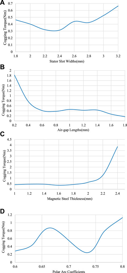
FIGURE 4. The maximum value of cogging torque when each parameter changes: (A) Maximum cogging torque at different stator slot widths, (B) Maximum cogging torque at different air-gap lengths, (C) Maximum cogging torque at different magnet thicknesses, (D) Maximum cogging torque at different polar arc coefficients.
3.4 Optimization results
During the cogging torque parameterization, different degrees of attenuation can be demonstrated by using different methods and changing the parameter range. It can be seen from Figure 4 that when the pole arc coefficient is between 0.72 and 0.74 and the thickness of the magnetic steel is between 1.6 mm and 1.8 mm, the calculated cogging torque is relatively lower. Considering that increasing the air gap will reduce the output torque of the motor, the length of the air gap should be kept between 0.6 mm and 1 mm. The cogging torque waveform before and after adjustment is shown in Figure 5. The cogging torque is reduced from 1.5 Nm to 0.15 Nm, and the optimized output torque waveform is more stable, the torque ripple is lower, and the optimization effect is more obvious.
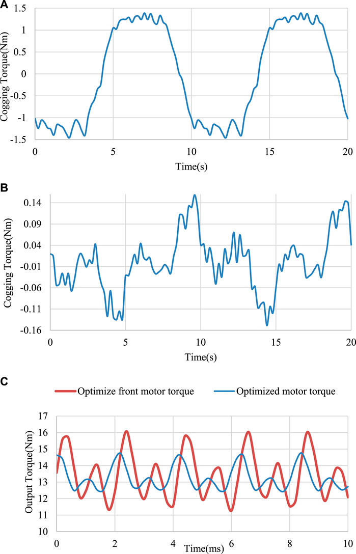
FIGURE 5. Waveform comparison before and after optimization: (A) Cogging torque waveform before optimization, (B) Cogging torque waveform after optimization, (C) Output torque waveform before and after optimization.
4 Electromagnetic characteristic analysis
4.1 Magnetic flux density
After the optimization is completed, use the finite element software Maxwell to establish a two-dimensional model of the motor, set the rated current on the inner and outer stator windings, and obtain the magnetic flux density cloud diagram of the permanent magnet assisted dual-rotor motor with load through finite element simulation. As shown in Figure 6, the maximum value of the magnetic flux density appears at the position of the inner and outer stator yoke, which is about 1.8T, which does not exceed the design limit of 2T and meets the motor operation specification.
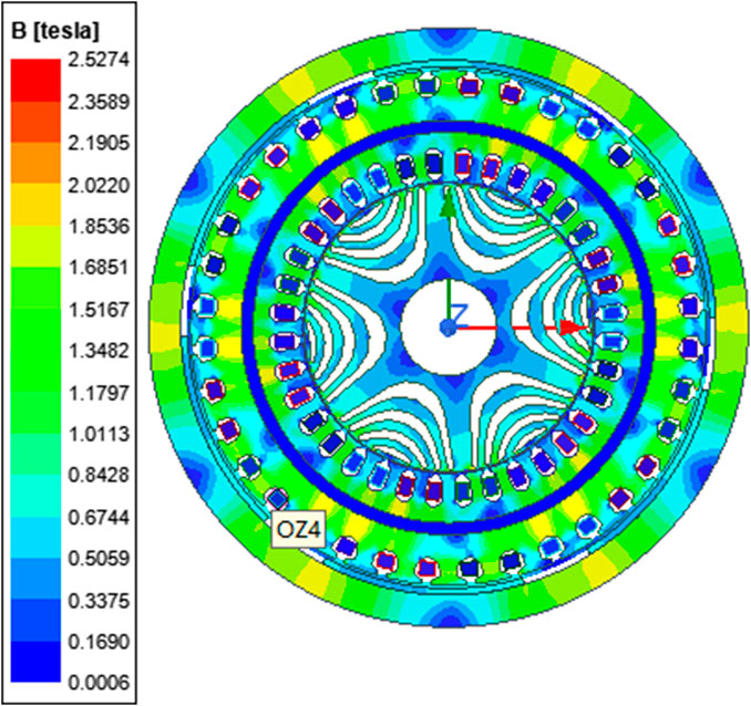
FIGURE 6. Motor magnetic field density map.
4.2 Air gap magnetic density
The air-gap magnetic field density is an important indicator of motor design. Figure 7 is the air-gap flux density curve of the internal and external motors under no-load and rated current. The amplitude of the air-gap flux density reflects the magnetic field strength and torque density of the motor, it can be seen that the waveform is closer to a sine wave. From the comparison of the two curves, we can see that the air gap flux density curve of the inner motor is more reasonable than the sinusoidal distribution of the outer motor, indicating that the inner motor can meet the requirements of torque output and power density. The peak values of the air gap magnetic density of the outer motor and the inner motor are 0.8T and 1 T, respectively, which generally meet the design requirements.
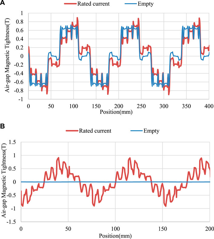
FIGURE 7. Air gap magnetic: (A) Outer motor air gap flux density and (B) Inner motor air gap flux density.
4.3 Output torque
Since the motor has a double-air-gap structure, its total output torque is the sum of the output torques of the inner and outer motors, and the torque output waveforms of the inner and outer motors are shown in Figure 8. According to the output torque results, the output torque of the inner rotor synchronous reluctance motor is about 4
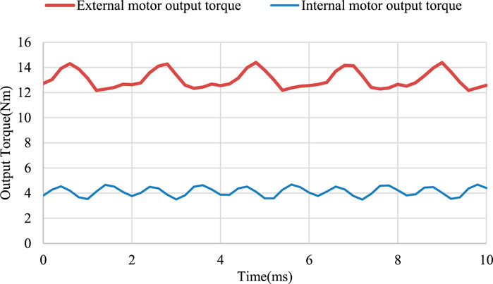
FIGURE 8. Output torque waveform of internal and external motors.
5 Design of control system for dual rotor motor
5.1 Motor mathematical model
The dual-rotor motor is composed of inner rotor, outer rotor, permanent magnet, magnetic isolation ring and other parts. It has the characteristics of strong coupling and nonlinearity. For the convenience of analysis, the assumptions are as follows: 1) Neglect eddy current and hysteresis loss; 2) Excitation current There is no response time; 3) The stator windings are star-connected, and the stator windings are connected in parallel. According to the above assumptions, it can be obtained that the dual-rotor motor can be split into a permanent magnet synchronous motor and a synchronous reluctance motor, and after transformation by
Since the double-rotor motor is divided into two parts, the inner rotor and the outer rotor, the electromagnetic torque of the motor is expressed as the permanent magnet torque of the outer motor and the reluctance torque of the inner motor, and the sum of the inner and outer torques is the total electromagnetic torque of the motor.
In these formulas,
5.2 Vector control
Vector control is based on the control idea of a DC motor, converts the three-phase current into excitation current and torque current, and realizes indirect control of the motor by changing the magnitude of the excitation current and torque current, that is, by controlling the axis current of the motor to achieve the purpose of controlling the motor. At present, the commonly used vector control methods of permanent magnet synchronous motors include
5.3 Torque distribution
Due to the existence of the magnetic isolation ring, the dual-rotor motor can be equivalent to a surface-mounted permanent magnet synchronous motor and a synchronous reluctance motor. Conventional control requires two sets of controllers that interact with each other. In order to solve this problem, torque distribution is introduced. Torque distribution is used to fix the ratio of the output torque of the internal and external motors, distribute the torque current of the internal and external motors, and simplify the control system.
5.4 Controller design
5.4.1 Current controller design
The current controller in this design adopts the mode of hysteresis control, also called bang-bang control, which has the characteristics of real-time control, fast reaction, and strong robustness. The implementation method is to change the switching state of the inverter by comparing the given current value with the detected current value, and then output the actual current in the shape of a sawtooth wave. Although there are certain errors, this current control method is simple and easy to implement and does not rely on motor parameters.
5.4.2 Speed controller design
The speed control of this design adopts the granular function instead of the fuzzy controller. The granular function is based on the theory of granular computing. Granular computing (GrC) is usually defined in an informal way as a general computing theory that can be used effectively. To build an efficient computational model for complex applications with large amounts of data, information, and knowledge (Bargiela and Pedrycz, 2008), the granular function shifts from a machine-centered approach to a human-centered approach. It is one of the trends in granular computing research (Yao, 2010), and fuzzy set theory is an application of granular computing (Zarandi Baghini et al., 2023). The construction of granular functions in fuzzy control is divided into steps such as information sampling, information granulation, and fitting. Using granular functions instead of fuzzy controllers can save steps such as fuzzification and defuzzification. The construction process of a granular computing fuzzy controller is shown in Figure 9.
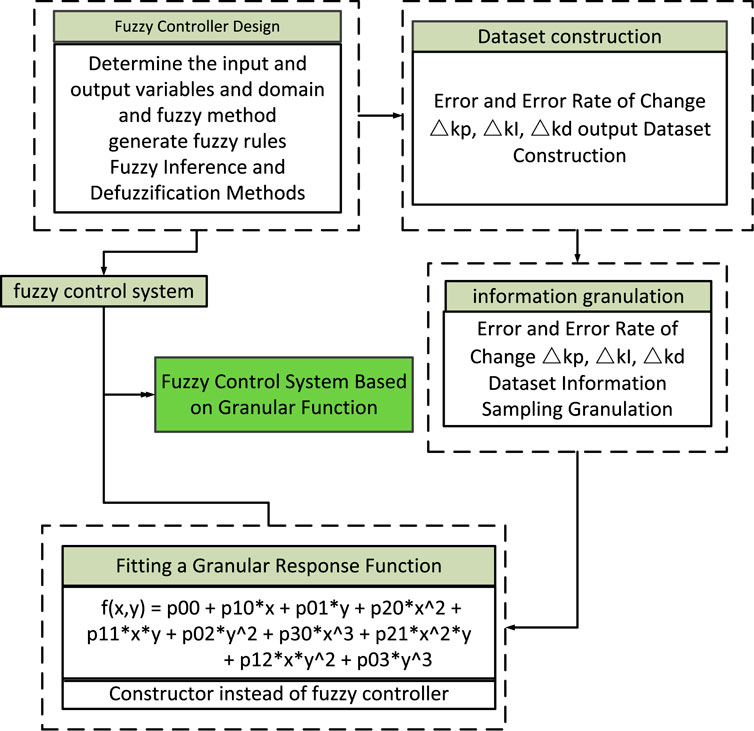
FIGURE 9. Construction process of granular function optimization fuzzy controller.
5.5 System simulation and analysis
5.5.1 Control system block diagram
According to the description of the fuzzy control optimized by the above granular function, a dual-rotor motor control system frame can be built as shown in Figure 10. The control system is composed of a traditional PID controller, a granular function optimization module, a torque distribution module, a current hysteresis controller, and a motor body.
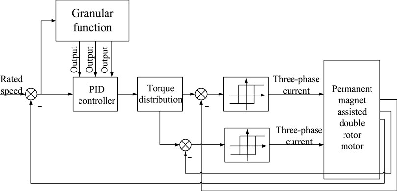
FIGURE 10. Control system block diagram.
5.5.2 Simulation result analysis
As shown in Figure 11, the highest speed for fuzzy control and granular function control is about 1,640 r/min, and after changing the load, fuzzy control and granular function control motors drop to 1,591 r/min. It can be concluded that the granular function is comparable to the fuzzy control in terms of control performance, but the granular function removes the complicated fuzzification and defuzzification processes, only needs one response function, and the simulation time is less than one-tenth of the fuzzy control.
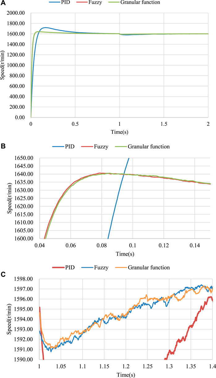
FIGURE 11. Motor output waveform: (A) The output waveforms of different control modes, (B) Partial enlarged view of the speed increase process. (C) Partial enlarged view of the speed drop process after.
6 Conclusion
This paper aims to address the problem that the cogging torque of a dual-rotor motor connected by concentric end disks affects the motor’s output torque. By deriving the motor power equation constraints, the fixed-value scanning method is used for optimization analysis. After optimization, the motor cogging torque was reduced from 1.5 Nm to 0.15 Nm, a reduction of 90%; the external rotor torque ripple was reduced by 50%; the torque output waveform was improved; and the optimized electromagnetic performance was verified. Finally, in order to simplify the motor control system, this paper uses granular functions to improve the fuzzy controller, performs feature sampling on fuzzy rules, and uses response functions to replace the fuzzy controller, omitting the fuzzification and defuzzification links. Simulation shows that after granular function optimization, the response speed of the system is significantly improved.
Data availability statement
The original contributions presented in the study are included in the article/Supplementary Materials, further inquiries can be directed to the corresponding author.
Author contributions
YZ and GX wrote and typed the manuscript, and XK provided writing guidance, checking and correction.
Funding
This work is supported in part by the National Natural Science Foundation of China under grant 51877139 and the Basic Scientific Research Project of Liaoning Provincial Department of Education of China under grant LJKMZ20220778.
Conflict of interest
The authors declare that the research was conducted in the absence of any commercial or financial relationships that could be construed as a potential conflict of interest.
Publisher’s note
All claims expressed in this article are solely those of the authors and do not necessarily represent those of their affiliated organizations, or those of the publisher, the editors and the reviewers. Any product that may be evaluated in this article, or claim that may be made by its manufacturer, is not guaranteed or endorsed by the publisher.
Supplementary material
The Supplementary Material for this article can be found online at: https://www.frontiersin.org/articles/10.3389/fenrg.2023.1240473/full#supplementary-material
References
Agbo, S., Samuel, O. D., Amosun, S. T., Oyejide, O. J., Fayomi, O. S. I., Bamisaye, O. S., et al. (2021). Development of a solar energy-powered surface water pump. IOP Publ. 1107 (1), 012002. doi:10.1088/1757-899X/1107/1/012002
Al-Ani, M. (2021). Multi-physics design and analyses of dual rotor synchronous reluctance machine. eTransportation 8, 100113. doi:10.1016/j.etran.2021.100113
Aravind, C. V., Norhisam, M., Aris, I., Marhaban, M. H., Ahmad, D., and Nirei, M. (2011). “Double-rotor switched reluctance machine (DRSRM): fundamentals and magnetic circuit analysis,” in 2011 IEEE Student Conference on Research and Development (IEEE), 294–299.
Bai, J., Zheng, P., Cheng, L., Zhang, S., Liu, J., and Liu, Z. (2015). A new magnetic-field-modulated brushless double-rotor machine. IEEE Trans. Magnetics 51 (11), 1–4. doi:10.1109/tmag.2015.2445917
Bargiela, A., and Pedrycz, W. (2008). Toward a theory of granular computing for human-centered information processing. IEEE Trans. Fuzzy Syst. 16 (2), 320–330. doi:10.1109/tfuzz.2007.905912
Diao, C., Zhao, W., Ding, H., and Wang, X. (2023). Design and analysis of low-cost double rotor axial flux permanent magnet synchronous motor.
Fu, D., Lv, Z., Si, H., Liu, Y., and Wu, X. (2023). Analysis and comparison of novel yokeless double rotor mutually coupled switched reluctance motor.
Hofmann, H., and Sanders, S. R. (2000). High-speed synchronous reluctance machine with minimized rotor losses. IEEE Trans. Industry Appl. 36 (2), 531–539. doi:10.1109/28.833771
Jurca, F., and Martis, C. (2017). “Analysis of outer rotor synchronous reluctance motor for low-speed applications[C],” in 2017 19th International Conference on Electrical Drives and Power Electronics (EDPE), Dubrovnik, Croatia, 04-06 October 2017 (IEEE), 242–247.
Li, J., Wang, J., Liu, J., and Ren, C. (2023). Coordinated control strategy for drive mode switching of double rotor in-wheel motor based on MPC and control allocation. World Electr. Veh. J. 14 (5), 132. doi:10.3390/wevj14050132
Li, Y., Bobba, D., and Sarlioglu, B. (2017). Design and optimization of a novel dual-rotor hybrid PM machine for traction application. IEEE Trans. Industrial Electron. 65 (2), 1762–1771. doi:10.1109/tie.2017.2739686
Liu, Y., and Li, J. (2022). Research on concentrated winding counter-rotating double rotor disk motor. Mech. Des. Manuf. (03), 110–113. doi:10.19356/j.cnki.1001-3997.20211115.003
Patel, A. N. (2023). Slot opening displacement technique for cogging torque reduction of axial flux brushless DC motor for electric two-wheeler application.
Qu, R., and Lipo, T. A. (2003). Dual-rotor, radial-flux, toroidally wound, permanent-magnet machines. IEEE Trans. industry Appl. 39 (6), 1665–1673. doi:10.1109/tia.2003.818968
Rashid, M. K., and Mohammed, A. M. (2023). A reduction method of cogging torque for magnetic gears. Iran. J. Electr. Electron. Eng. 19 (2), 2752. doi:10.22068/IJEEE.19.2.2752
Shirzad, E. (2023). Calculation of flux density in air-gap for reluctance motor with two ports (Double-Stator, double-rotor) by fourier series.
Wang, D., Wang, X., Qiao, D., Pei, Y., and Jung, S. Y. (2011). Reducing cogging torque in surface-mounted permanent-magnet motors by nonuniformly distributed teeth method. IEEE Trans. Magnetics 47 (9), 2231–2239. doi:10.1109/tmag.2011.2144612
Wang, H., and Leng, J. (2018). “Summary on development of permanent magnet synchronous motor,” in 2018 Chinese Control And Decision Conference (CCDC) (IEEE), 689–693.
Wang, L., Lu, S., Chen, Y., and Wang, S. (2023). An in-phase unit slot-opening shift method for cogging torque reduction in interior permanent magnet machine. Mathematics 11 (7), 1735. doi:10.3390/math11071735
Won, Y. J., Kim, J. H., Park, S. H., Lee, J. H., An, S. M., Kim, D. Y., et al. (2023). Transfer learning-based design method for cogging torque reduction in PMSM with step-skew considering 3-D leakage flux. IEEE Trans. Magnetics, 1. doi:10.1109/tmag.2023.3294601
Yao, J. (2010). Novel developments in granular computing: applications for advanced human reasoning and soft computation: applications for advanced human reasoning and soft computation. IGI Glob.
Yunyun, C., Li, Q., Xiaoyong, Z., Hua, W., and Wang, Z. (2012). Electromagnetic performance analysis of double-rotor stator permanent magnet motor for hybrid electric vehicle. IEEE Trans. Magnetics 48 (11), 4204–4207. doi:10.1109/tmag.2012.2206374
Keywords: dual rotor, permanent magnet synchronous motor, cogging torque, parameter scan, granular function
Citation: Kong X, Zhang Y and Xu G (2023) Optimal design and control of permanent magnet assisted dual rotor motor. Front. Energy Res. 11:1240473. doi: 10.3389/fenrg.2023.1240473
Received: 15 June 2023; Accepted: 12 September 2023;
Published: 26 September 2023.
Edited by:
Olusegun David Samuel, Federal University of Petroleum Resource Effurun, NigeriaReviewed by:
Andrea Toscani, University of Parma, ItalyKenneth E. Okedu, Melbourne Institute of Technology, Australia
Copyright © 2023 Kong, Zhang and Xu. This is an open-access article distributed under the terms of the Creative Commons Attribution License (CC BY). The use, distribution or reproduction in other forums is permitted, provided the original author(s) and the copyright owner(s) are credited and that the original publication in this journal is cited, in accordance with accepted academic practice. No use, distribution or reproduction is permitted which does not comply with these terms.
*Correspondence: Xiaoguang Kong, a29uZ3hpYW9ndWFuZ0BzeXVjdC5lZHUuY24=