 Arqum Shahid1†
 Sajjad Manzoor
 Afraz Hussain Majeed
 Ilyas Khan
- 1Department of Electrical Engineering, Mirpur University of Science and Technology (MUST), Mirpur, AJK, Pakistan
- 2Department of Electrical Engineering, CUI, Abbottabad Campus, Abbottabad, Pakistan
- 3School of Energy and Power Engineering, Jiangsu University, Zhenjiang, China
- 4Department of Mathematics, College of Science Al-Zulfi, Majmaah Univversity, Al-Majmaah, Saudi Arabia
- 5Research Centre, Future University in Egypt, New Cairo, Egypt
Battery charging systems are integral to the efficient operation and economic benefit of various applications, from electric vehicles to renewable energy storage. However, maintaining battery charging according to specifications during voltage variations, including short or prolonged under-voltage and over-voltage conditions, presents a significant challenge. These voltage variations can impact the thermal safety and charging time of batteries, potentially affecting their overall performance and life span. In order to address these challenges, this paper proposes a smart charging control method designed to control both the battery charging voltage and load voltages. This method is equipped to handle utility interruptions by using regulated AC–DC converters, while an automatic interconnected DC regulator controls the battery state of charge (SOC) and load supply. This dual control mechanism ensures efficient performance under various conditions. Extensive simulations validate the effectiveness of the proposed method, demonstrating its ability to maintain a constant voltage supplied to the load and ensures the thermal safety of the system during under- and over-voltage conditions. Additionally, an analysis of the thermal effect of the charger under these voltage conditions provides valuable insights into the thermal performance of the system, which is a critical aspect of battery charging systems. The proposed charging control method offers a comprehensive solution for efficient battery charging under various voltage conditions, thus contributing to the better performance, thermal safety, and longevity of batteries.
1 Introduction
Recently, there has been much research on excessive energy storage to achieve sustainability (Mahlia et al., 2014). Electrochemical batteries are major energy storage elements used for powering electrical instruments, from small scale applications such as flash lights and mobile phones to large scale industrial units, telecommunication systems, and electric vehicles (Yilmaz and Krein, 2012; Akinyele et al., 2017; Hasan and Altinoluk, 2023). They are useful in providing uninterrupted power to consumers (Yekini Suberu et al., 2014) and have high energy density, better life span, and a suitable energy cost.
Electrochemical batteries are either primary (non-rechargeable) or secondary (rechargeable). This reuse capability makes secondary batteries more popular to use. There is, therefore, an increase in research into their development and the improvement of charging mechanisms. Battery energy storage systems (BESSs), equipped with power-electronics devices and control systems (Diaz-Gonzalez et al., 2012), are designed to effectively charge and discharge a battery. Different techniques are used to mitigate the voltage variations and undesired state of charge (SOC) during battery charging, such as maximum power point (MPP) tracking controllers, and drop-based control systems (Daud et al., 2013; Jamroen et al., 2018). In MPP control systems, the boost converter can be operated in on- or off-MPPT according to the power balance of the system and the SOC of the battery. A battery temperature control system that turns the thermo-electric coolers on and off to reduce internal power loss has been designed by Alaoui (2017).
By using a DC–DC converter between the rectifier and battery bank, DC-link voltage can be achieved that provides more freedom to control battery SOC and connected load; however, DC–DC converters must be bi-directional to control power flow during charging and discharging (Qian et al., 2011; Zeraati et al., 2018). Three-level DC–DC converters are highly suitable for high input/output voltage and medium-to-high-power DC–DC power conversions. The advantages of three-level converters include reduced voltage stress on the switches, reduced filter size, and improved dynamic response (Ruan et al., 2008). In order to charge time-varying loads, a high-gain battery-integrated DC–DC boost converter (HGBIBC) has been proposed by Saxena and Kumar (2021) which has low component counts with two switches and the two diodes, and is specifically designed to increase battery life.
The battery charger for the BESS proposed in Shi et al. (2018) utilizes a propulsion motor as a coupled DC inductor between AC–DC and DC–DC converters for power factor correction, and a control system is designed to regulate battery current and voltage. A proportional–integral (PI) controller-based inner loop system regulates the output voltage and motor current on the basis of motor excitation. However, the complexity of the charger is very high. A novel bi-directional battery charger is designed in Gallardo-Lozano et al. (2011) that intakes and injects power to the grid during battery charging and system demand, respectively. A control system based on battery current is designed so that the charger injects harmonic free current into the grid, in phase with the positive sequence fundamental component of the phase-to-neutral grid voltage in order to attain a unity power factor.
A major problem faced by consumers is sudden over-voltage or under-voltage, which may damage equipment and affect batteries. When a battery is charged at high voltage, it may eventually burst due to the production of explosive gases. It may also damage the charging circuit as well as the device supplied by batteries. On the other hand, under-voltage conditions may delay the recharge of batteries. Temperature is a critical factor that significantly impacts the performance of lithium-ion batteries and also limits their application. Moreover, different temperature conditions result in different adverse effects. Temperature may affect a battery’s performance (Ma et al., 2018). Generally, the acceptable temperature range for lithium-ion batteries is −20°C ∼ 60°C (Ji et al., 2013). High charging voltage may lead to battery gassing, corrosion, or unwanted heating (Belov and Yang, 2007). The impact of high charging voltage on lithium-ion batteries in form of rising battery temperature is discussed by Zhang et al. (2014). Similarly, during a fast-charging process, current that is not properly controlled may lead to a battery burning. Charging batteries at low temperature reduces the chemical reaction rate due to increasing internal resistance, which reduces battery capacity and affects battery life (Petzi et al., 2015). Charging/discharging operations at high temperature reduces battery life due to accelerated chemical processes (Timmermans et al., 2016).
This paper proposes a new battery charging mechanism by considering both the conditions of over- and under-voltage that may occur in the AC power source. The suggested control would help prevent any battery overheating due to over-voltage. It will also regulate battery charging time by controlling any under-voltage. In addition, the proposed system is further improved to provide constant voltage to a load from source or the battery. The novelty of the control scheme lies in its comprehensive approach to battery charging, effectively managing voltage variations, ensuring thermal safety, and maintaining a constant voltage supply to the load. The effectiveness of the proposed method under various voltage conditions will be demonstrated through simulation.
This paper is further organized as follows. Section 2 outlines the shortcomings of existing work and solutions proposed to overcome the issue. Section 3 discusses the system used in this paper along with the method used to improve battery charging. A control scheme proposed to overcome voltage variations in power sources is also discussed in the section. Section 4 gives the simulation results in order to validate the proposed method. Section 5 concludes the paper and discusses expected future development of the proposed device.
2 Statement of interest
Being an important research topic in micro-grids, there has been much recent research on battery charging control (Urtasun et al., 2017; Mohammadi et al., 2019; Vrana et al., 2020; Wang et al., 2021; Alrashidi, 2022; Yenku et al., 2022). A major issue with battery charging systems is that variations in supply voltage are applied without taking them into consideration while designing controllers, preventing the system from working effectively. Consequently, battery charging voltage also varies and its charging current increases due to battery internal cell resistance; this may result in SOC variation. Most work on battery charging systems does not seem to take this issue into consideration. Some major shortcomings in existing research are:
• Variations in power source can lead to abrupt changes in battery charging current due to internal battery cell resistance. This results in an increase in battery voltage and SOC variations.
• Existing battery charging systems may not effectively control over- and under-voltage in power supply along with the current supplied to the battery.
• Existing systems may not supply a fixed voltage across the load in the case of under-voltage conditions in the power source.
• The direction of power supply to the load either from source or from the battery may not be decided automatically in existing systems.
We here propose a battery charging control system by taking into consideration the shortcomings of existing research. In particular, our system will help avoid conditions of over- and under-voltage that may occur in the AC power supply. The proposed control mechanism will also help prevent overheating of the battery in over-voltage, along with regulating battery charging time during any under-voltage condition. The following features are introduced in the proposed solutions to bridge these shortcomings:
• The proposed controller mitigates the variations in voltage and current, reducing them almost to zero. This controller is designed to improve any variation in the power source.
• The proposed charging system prevents any increase in lithium-ion battery temperature and controls its charging time by controlling over- and under-voltage in power supply along with the current supplied to it.
• The designed charger supplies a fixed voltage across the load in case of under-voltage in the power source.
• The charger we design automatically decides the direction of power supply to the load either from source or the battery.
3 Materials and methods
This section discusses a proposed charger design for a lithium-ion battery. A schematic diagram of the charging system that effectively manages battery charging under various voltage conditions is given in Figure 1. The control scheme uses a PI controller and Clark and Park transformations, which are existing techniques; however, they are uniquely applied to address the specific challenges of battery charging. The proposed system would prevent any increase in battery temperature and control its charging time by controlling over- and under-voltage in power supply along with the current supplied to it.
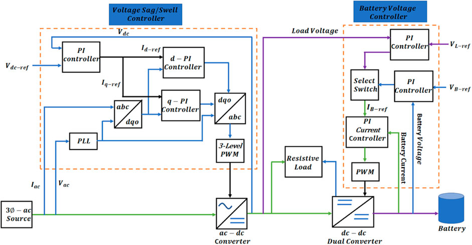
FIGURE 1. Schematic diagram of voltage variation and battery charging control system.
Three-phase AC power is initially converted to DC through an AC–DC converter. A DC–DC converter, controlled by a DC–DC voltage control system, is used to convert DC voltage into the optimal voltages required for battery charging. A constant-current constant-voltage control strategy is used for battery charging. For load-following application, a resistive load is connected between the charger and the battery. The battery charging scheme is further designed to supply fixed voltage across the load in case of any interruption or under-voltage condition in the power source. The direction of power supply to the load, either from source or from the battery, is automatically decided through the proposed scheme.
3.1 AC to DC voltage control system
The purposed AC–DC voltage control system is designed to keep the BESS safe from source voltage variations. A PI controller is used with the ability to regulate DC voltage by eliminating forced oscillations and steady state error (Patil, 2014). In the AC–DC control of Figure 1, the AC current—
while
where θ is continuous the angular displacement of the generator.
The Park transformation is used to convert AC current into a rotating reference frame—positive, negative, and zero sequence components. This transformation is crucial for managing the variations in the power source and ensuring the stability of the charging process. A phase-locked loop (PLL) detects the phase angle of the AC voltage signal and maintains the generated signal in fixed phase relation to the reference signal. Two separate PI controllers are used: one for the positive sequence current (d-current) and the other for the negative sequence current (q-current) (Sharma et al., 2020). When DC voltage from the converter output is compared with the reference voltage Vdc−ref, an error signal is produced which, after passing through the PI controller, acts as a reference signal for the positive and negative sequence components. The output of the two controllers’ positive and negative components are then converted to three phase components Iabc by adding the phase angle of the PLL using inverse Park transformation as:
while
At the end, the three-level PWM generator converts the refined signal generated by inverse Park transformation into an appropriate gate signal for a three-phase AC–DC converter.
3.2 DC to DC control system
Different batteries follow different patterns for their appropriate charging; inappropriate charging can damage batteries and also increase their charging time. There are three common methods of battery charging: constant voltage (CV), constant current (CC), and constant-current constant-voltage (CCCV). In the CV method, full charging current is applied to the battery and maintains the same voltage. In the CC method, full charging voltages are applied across the battery, while the current is set to 10% of the battery’s nominal current. In the CCCV method, a combination of CC and CV methods is used, where the battery is initially charged with a constant current, then the charging current decreases exponentially with the increase in battery SOC.
The proposed charging method is CCCV (Figure 1), where IB and IB−ref represent the actual charging current and reference charging current, respectively. In a control scheme, a DC–DC converter maintains the voltage across the battery with respect to the source voltage. This converter is also dual, as it also supplies current to the load. Here, a battery current control scheme, based on a PI controller, compares the battery charging current with the reference current IB−ref to obtain the error signal. The PI control is used to regulate DC voltage by eliminating forced oscillations and steady-state error. This is particularly important in the context of battery charging, where voltage variations can lead to abrupt changes in battery charging current due to internal battery cell resistance. This, in turn, can result in an increase in battery voltage and SOC variations.
The value of the proportional and integral gain in the PI current controller is shown in Table 1. The tuning of the PI controller was achieved using the MATLAB Simulink built-in PID Tuner Tool to adjust the gains by achieving a balance between performance (speed of response) and robustness (stability margins) based on the system response. The reference current IB−ref provided to the PI controller for current was the output of the PI controller for voltage. A select switch was used to get the reference current from either the output of the PI controller using battery voltage as a reference VB−ref for battery charging or the PI controller using load voltage as a reference VL−ref to provide supply to the load. After passing through the PI controller, the error signal acts as a modulated signal in the PWM generator of the DC–DC converter.
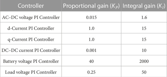
TABLE 1. Proportional and integral gain for PI controllers.
3.3 Voltage control system for load flowing application
Some loads require continuous and constant DC supply for applications such as operating a substation circuit breaker, an indication or protection alarm, or protection relay. They are supplied from both source and BESS. A load is connected between the battery and the source voltage and is supplied by some fixed DC voltages. During the battery charging phase, power is supplied to the load from the charger, while the battery is charged or, during voltage variation imposed from the source, power is supplied from the battery to keep load voltage constant. Figure 1 shows the load voltage control system, where a constant VL−ref is maintained across the load. The actual voltage across the load is compared with the required DC voltage for the load, and the PI controller generates a required reference signal for the battery charging current control. Therefore, the proposed control scheme includes an automatic interconnected DC regulator that controls the battery SOC and load supply. This feature allows the system to automatically decide the direction of power supply to the load either from the source or from the battery, depending on the current conditions.
The summary of control for battery charging and voltage regulation is given in Algorithm 1.
Algorithm 1.Control algorithm for battery charge and voltage regulation.
Require: Regulate VB & Regulate VL
Given: VB−ref & VL − ref & VS
Ensure: VS ← 1p.u.
VB ← VB−ref
VL ← VL−ref
if VS ≠ 1 p.u. & VS ≠ 0 then ⊳ Over- or under-supply voltage without interruption
Voltage sag/swell controller generates 3-level PWM for AC-DC converter
IB−ref ← PI with VB−ref
else if VS = 0 then ⊳ supply voltage interruption
IB−ref ← PI with VL−ref
Load is supplied power from the battery
else ⊳ Normal operation
do the default actions
end if
3.4 Converters
It can be seen in Figure 1 that two different converters are used in the control scheme. The first is a simple three phase AC–DC bridge converter, which allows the switching devices to operate at low frequency, thus reducing the harmonic and switching losses. A three-level PWM signal generated by inverse Parks transformation is used as the gate signal for this three-phase AC–DC converter. The second converter is a dual DC–DC converter which changes DC voltage from one level to another. It is a half bridge bidirectional buck-boost converter (Figure 2) and is used to charge the battery as well as to supply voltage to the load from it by adding a governable switch to it. During battery charging, the voltage is supplied by the power source while, during discharge, it is supplied by battery. In our case, the battery voltage is 24 V while that of load voltage is 48 V.
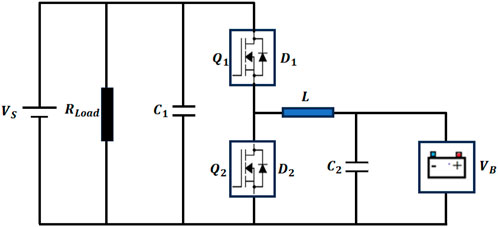
FIGURE 2. Topological structure of bi-directional buck-boost converter.
The bidirectional buck-boost converter consists of two simple buck and boost converters connected in an anti-parallel fashion. A DC–DC converter maintains the voltage across the battery and load with respect to source voltage. When Q1 is switched on and Q2 is switched off, the converter acts in buck mode, and the energy flows from source voltage (high) to battery (low). When Q2 is switched on and Q1 is switched off, the converter acts in boost mode, where energy is transmitted from battery (low) to source or load (high) voltage and the value of the voltage rises (Li et al., 2017).
With VS being source voltage (same as load voltage), VB being battery voltage, and D being the duty ratio of the PWM signal, the relationship between the input and output voltages in the buck mode is given as
while the relationship between the input and output voltages in the boost mode is given as:
4 Results
The working of a smart energy charger was analyzed by MATLAB simulation to charge a 24 V battery. The battery’s initial state of charge was adjusted to 45%. The voltage amplitude in the three-phase voltage source is varied along with the time period, such that, with initial value 1 [pu], at time 0.5 [s] it is converted to 0.8 [pu], 4, at time 1 [s] it is changed to 0.6 [pu], at time 1.6 [s] it is increased to 1.2 [pu], at 1.8 [s] it is again reduced to .9 [pu], and at 2.3 [s] it is again adjusted to normal at 1 [pu] as shown in Table 2. The effect on the battery charging with and without the proposed control was observed for 3 [s], in the simulations. A resistive load that needs a constant voltage of 48 V is attached to the system so that it can be observed so that, in the case of any under-voltage in the supply system, the proposed controller can direct the battery to compensate. The direction of power supplied to the load is automatically controlled.

TABLE 2. Variation in input voltage with time.
Variations applied without designed controllers disturb the battery charging control system; as a result, battery charging voltage also varies, while battery charging current becomes abrupt due to battery internal cell resistance. This results in increase in battery voltage and SOC variations. In Figure 3, the effect of various under- and over-voltages on battery charging voltage and the current is given where portions of output at various input voltage levels are segregated for convenience. It can be observed in Figure 3B that, at time T = 0.5 s, where the source voltage decreases to 0.8 pu, the battery charging current remains almost uniform at 16 amp due to small changes in charging voltage. When variations are applied without designed controllers, battery charging voltage decreases at 1 [s] where source voltage is decreased to 0.6 pu and increases above normal value, at 1.6 [s] where source voltage is increased to 1.2 pu. It again decreases at 1.8 [s] to 0.9 pu and becomes normal 2.3 [s]. This would result in variations of the abruptness in battery charging current due to battery internal cell resistance (Figure 3). It can be observed that, when the proposed controller is added to the system, the variations in voltage and current are almost zero and remain constant.
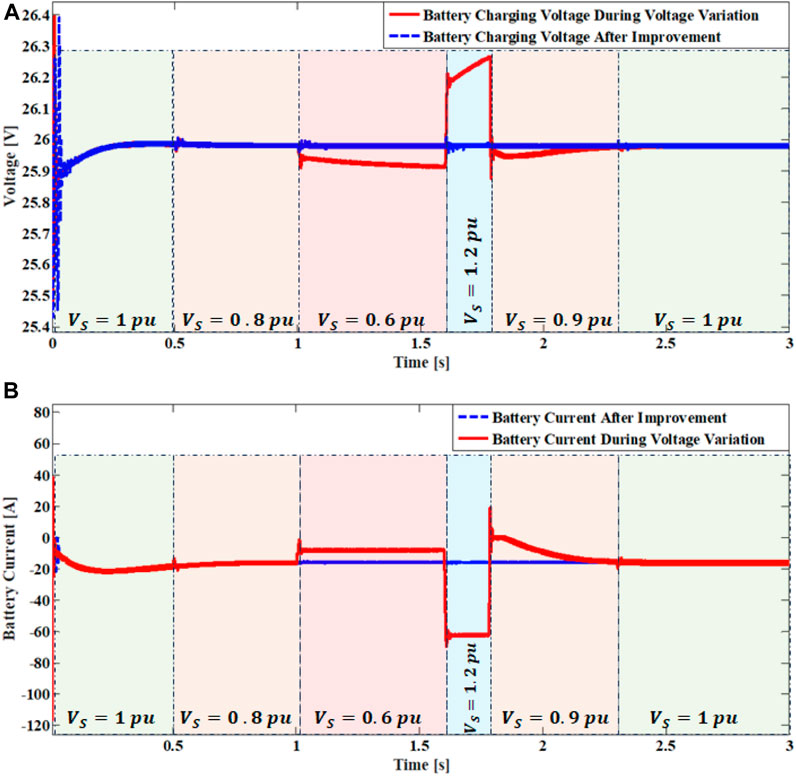
FIGURE 3. (A) Battery charging voltage variations with and without controller and (B) battery charging current variations with and without application of voltage improvement controller.
When source voltage decreases, battery charging voltage also decreases, and it increases with increases in source voltage. Thus, the decrease in source voltage would slow the charging process and increase charging time. However, if charging voltage becomes less than the minimum voltage required for battery charging, the battery starts discharging due to higher internal potential. Battery state of charge (SOC) is shown in Figure 4. From 1 [s] to 1.6 [s], where the drop in source voltage is large, the battery SOC slope changes abruptly, while it increases when charging voltage increases.
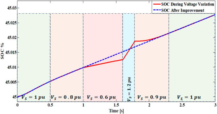
FIGURE 4. Battery SOC with and without application of voltage improvement controller.
With increases in charging voltage and current, battery temperature also increases, as given by relation:
where H is heat, I is current through circuit, R is battery resistance, and T is time. The battery temperature is shown in Figure 5. At time T = 0.5 s, source voltage decreases to 0.8 pu. The battery charging current remains almost uniform at 16 Amp due to small changes in charging voltage. Thus, SOC and temperature also witness a very small decrement. At time T = 1 s, source voltage decreases to 0.6 pu, resulting in a clear decrease in battery charging voltage to 25.91 V. Battery SOC and temperature significantly changed. At time T = 1.6 s, source voltage increases to 1.2 pu, resulting in a massive increase in battery charging current to 68 Amp and, as a result, battery temperature and SOC significantly increase. At time T = 1.8 s, source voltage decreases to 0.9 pu, and battery charging current also decreases due to abruptness to the charging voltage. The smart charger maintains the SOC constant and prevents the battery from heating by keeping the battery charging current within the specified 22 Amp by using AC–DC and DC–DC voltage control systems.
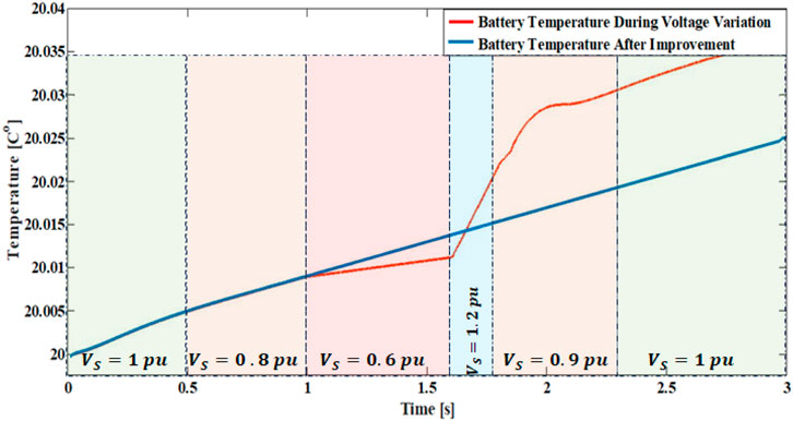
FIGURE 5. Battery temperature variations with and without application of voltage improvement controller.
The smart charger maintains the SOC constant and prevents the battery from heating by keeping the battery charging current within the specified 22 Amp by using AC–DC and DC–DC voltage control systems. The working of the battery current controller under three different conditions is shown in Figure 6. If no voltage variation is applied to the AC power supply, the output value of the PI controller remains constant (Figure 6A). With any variation in supply voltages without applying voltage sag/swell controller, the normal operation of the PI controller will be disturbed (Figure 6B). This alters the battery charging voltage, as the DC–DC converter did not receive the required gate signal. Figure 6C shows that, by applying the sag/swell controller with voltage variations, the output of the battery current PI controller remains same as when no variations are applied, with only small changes at the time of variation.
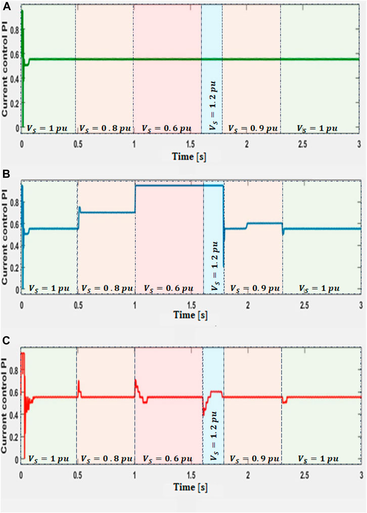
FIGURE 6. Battery current controller output under different conditions: (A) without change in input voltage, (B) with voltage variations, and (C) after voltage improvement.
In Figure 7 the PWM waveform for AC–DC and DC–DC converters is given with and without voltage improvement controller. It is apparent that, without the voltage improvement controller (Figure 7A), the PWM for the AC–DC converter shows no change in switching time with voltage variations 1, 2, 3, and 4. However, in this case, the duty cycle for the DC–DC converter PWM (Figure 7C) generates a different duty cycle. On the other hand, with the voltage improvement controller (Figure 7C), the PWM for the AC–DC converter shows a change in switching time with voltage variations 1, 2, 3, and 4. In such conditions, the duty cycle for the DC–DC converter PWM (Figure 7D) remains stable. It should be remembered that the PWM for the whole simulation time period is not given since it is difficult to see. Furthermore, the PWM for only three switches is given so that it can be seen easily.
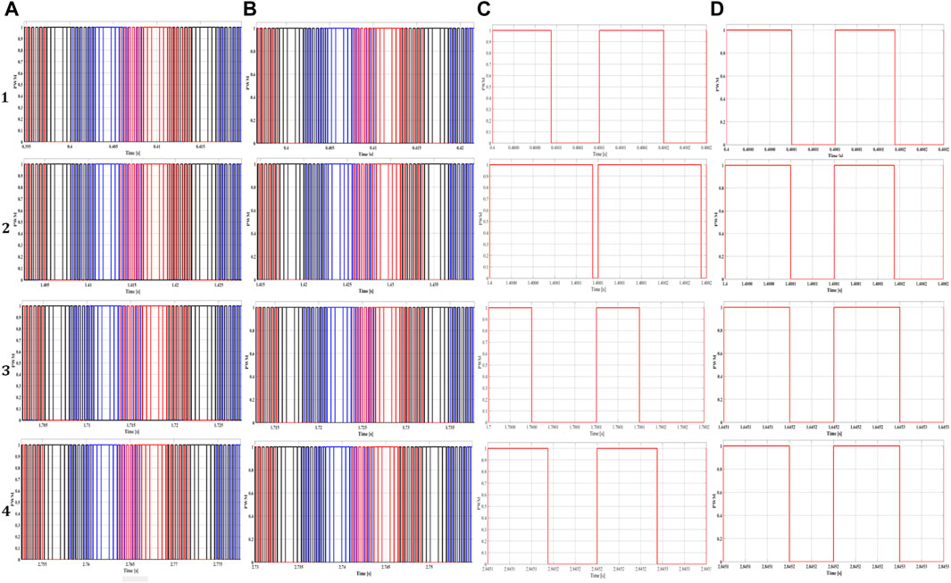
FIGURE 7. PWM for converters: (A) AC–DC without voltage improvement, (B) AC–DC with voltage improvement, (C) DC–DC without voltage improvement, and (D) DC–DC with voltage improvement controller AC–DC. With 1) normal voltage, 2) under-voltage, 3) over-voltage, and 4) normal voltage (again).
Figure 8 shows the voltage variation in a 15 Ω resistive load connected between charger and battery which needs a constant voltage supply of 48 V. In order to achieve this load-following property, a load voltage control system is designed. At the time instant of 0.5 s, voltage across the load without improvement was 39 V; load voltage control brings the voltage back to 48 V. During battery charging, the switch automatically turns off the power supply from the battery. If the battery is fully charged, the power to load is supplied by source. At the time of interruption, the switch shifts the power supply from source to battery and maintains 48 V across the load. At each increase or decrease in source voltage, the corresponding load voltage increases, which is corrected by the proposed controller.
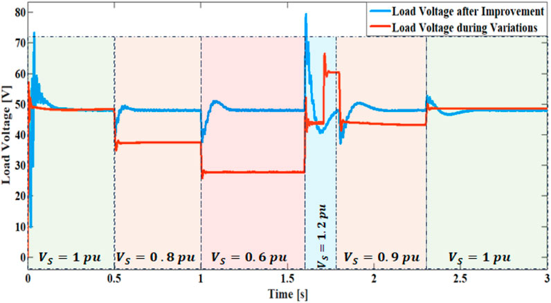
FIGURE 8. Variations in load voltage with change in input, with and without voltage improvement methods.
5 Concluding remarks
The present study explores the impacts of system voltage variation on battery charging. A supply voltage exceeding the normal range can adversely affect not only the battery but also the charging apparatus. On the other hand, a supply voltage falling below the normal range can potentially extend a battery’s charging time. Moreover, continuous fluctuations in the battery’s state of charge (SOC), attributed to supply voltage instability, can impair its capacity, and subsequently shorten its life cycle.
To circumvent the issues discussed previously, a novel charging mechanism for batteries is proposed which is designed to accommodate the over- and under-voltage conditions of the incoming power supply. A control system is developed to safeguard the battery from overheating and to maintain its SOC. AC–DC and DC–DC control systems yield distinctive results by mitigating the impacts of voltage variations. The proposed mechanism successfully prevents temperature rise during over-voltage and any charging delay. The load is connected to the incoming power supply, and the charger compensates for the voltage supplied to the load. Simulations reveal that the proposed charging system effectively enhances battery charging. Load voltage control proves particularly beneficial for voltage-sensitive instruments, especially in the context of security, system protection, and hybrid vehicles. While an increase in temperature could potentially improve battery performance, as it draws more current in the case of lithium-ion batteries, it could also shorten battery life. Therefore, the smart energy charger provides thermal protection by restricting the current and voltage to the specified range. The load-following property is crucial in areas where DC loads require a constant power supply, such as security systems. Future work will focus on proposing a more robust controller for the battery charger and to considering inductive load. The proposed controller will also be implemented in future experiments.
Data availability statement
The original contributions presented in the study are included in the article/Supplementary material; further inquiries can be directed to the corresponding author.
Author contributions
AS: writing—original draft and conceptualization; SM: software and supervision. UK and AM: writing—review and editing. IK: data curation and visualization. AM: modeling and writing—review and editing. All authors contributed to the article and approved the submitted version.
Funding
This work was supported by the Technology Development Fund (Grant No. TDF02-203), Higher Education Commission, Pakistan.
Conflict of interest
The authors declare that the research was conducted in the absence of any commercial or financial relationships that could be construed as a potential conflict of interest.
Publisher’s note
All claims expressed in this article are solely those of the authors and do not necessarily represent those of their affiliated organizations, or those of the publisher, the editors and the reviewers. Any product that may be evaluated in this article, or claim that may be made by its manufacturer, is not guaranteed or endorsed by the publisher.
References
Akinyele, D., Belikov, J., and Levron, Y. (2017). Battery storage technologies for electrical applications: impact in stand-alone photovoltaic systems. Energies 10 (11), 1760. doi:10.3390/en10111760
Alaoui, C. (2017). Thermal management for energy storage system for smart grid. J. Energy Storage 13, 313–324. doi:10.1016/j.est.2017.07.027
Alrashidi, M. (2022). Community battery storage systems planning for voltage regulation in low voltage distribution systems. Appl. Sci. 12 (18), 9083. doi:10.3390/app12189083
Belov, D., and Yang, M. H. (2007). Failure mechanism of Li-ion battery at overcharge conditions. J. Solid State Electrochem. 12 (7-8), 885–894. doi:10.1007/s10008-007-0449-3
Daud, M., Mohamed, A., and Hannan, M. (2013). An improved control method of battery energy storage system for hourly dispatch of photovoltaic power sources. Energy Convers. Manag. 73, 256–270. doi:10.1016/j.enconman.2013.04.013
Diaz-Gonzalez, F., Sumper, A., Gomis-Bellmunt, O., and Robles, R. V. (2012). A review of energy storage technologies for wind power applications. Renew. Sustain Energy 16, 2154–2171. doi:10.1016/j.rser.2012.01.029
Gallardo-Lozano, J., Milanes-Montero, M. I., Guerrero-Martinez, M. A., and Romero-Cadaval, E. (2011). “Three-phase bidirectional battery charger for smart electric vehicles,” in 2011 7th International Conference-Workshop Compatibility and Power Electronics (CPE).
Hasan, M., and Altinoluk, H. S. (2023). Current and future prospective for battery controllers of solar PV integrated battery energy storage systems. Front. Energy Res. 11, 1139255. doi:10.3389/fenrg.2023.1139255
Jamroen, C., Pannawan, A., and Sirisukprasert, S. (2018). “Battery energy storage system control for voltage regulation in microgrid with high penetration of PV generation,” in 2018 53rd International Universities Power Engineering Conference (UPEC), 1–6.
Ji, Y., Zhang, Y., and Wang, C. Y. (2013). Li-ion cell operation at low temperatures. J. Electrochem. Soc. 160 (4), A636–A649. doi:10.1149/2.047304jes
Li, B. Y., Xu, C., Lib, C., and Guan, Z. (2017). Working principle analysis and control algorithm for bidirectional DC/DC converter. J. Power Technol. 97 (4), 327–335.
Ma, S., Jiang, M., Tao, P., Song, C., Wu, J., Wang, J., et al. (2018). Temperature effect and thermal impact in lithium-ion batteries: A review. Prog. Nat. Sci. Mater. Int. 28 (6), 653–666. doi:10.1016/j.pnsc.2018.11.002
Mahlia, T. M. I., Saktisahdan, T. J., Jannifar, A., Hasan, M. H., and C Matseelar, H. S. (2014). A review of available methods and development on energy storage; technology update. Renew. Sustain. Energy Rev. 33, 532–545. doi:10.1016/j.rser.2014.01.068
Mohammadi, F., Nazri, G. A., and Saif, M. (2019). A bidirectional power charging control strategy for plug-in hybrid electric vehicles. Sustainability 11 (16), 4317. doi:10.3390/su11164317
Patil, M. (2014). Modelling and simulation of dc drive using PI and PID controller. Int. J. Innovative Res. Electr. Electron. Instrum. Control Eng. 2 (12).
Petzi, M., Kasper, M., and Danzer, M. A. (2015). Lithium plating in a commercial lithium-ion battery: A low-temperature aging study. J. Power Sources 275, 799–807. doi:10.1016/j.jpowsour.2014.11.065
Qian, H., Zhang, J., Lai, J., and Yu, W. (2011). A high-efficiency grid-tie battery energy storage system. IEEE Trans. Power Electron. 26 (3), 886–896. doi:10.1109/tpel.2010.2096562
Ruan, X., Li, B., Chen, Q., Tan, S. C., and Tse, C. K. (2008). Fundamental considerations of three-level DC–DC converters: topologies, analyses, and control. IEEE Trans. Circuits Syst. I, Reg. Pap. 55 (11), 3737–3743.
Saxena, A. R., and Kumar, D. (2021). Design and control of a reconfigurable high-gain battery integrated dc-dc boost converter for time-varying loads. Int. J. Circuit Theory Appl. 49 (2), 327–347. doi:10.1002/cta.2888
Sharma, S., Aware, M. V., and Bhowate, A. (2020). Integrated battery charger for EV by using three-phase induction motor stator windings as filter. IEEE Trans. Transp. Electrification 6 (1), 83–94. doi:10.1109/tte.2020.2972765
Shi, C., Tang, Y., and Khaligh, A. (2018). A three-phase integrated onboard charger for plug-in electric vehicles. IEEE Trans. Power Electron. 33 (6), 4716–4725. doi:10.1109/tpel.2017.2727398
Timmermans, J. M., Nikolian, A., de Hoog, J., Gopalakrishnan, R., Goutam, S., Omar, N., et al. (2016). “Batteries 2020-Lithium-ion battery first and second life ageing, validated battery models, lifetime modelling and ageing assessment of thermal parameters,” in 2016 18th European Conference on Power Electronics and Applications (EPE16 ECCE Europe).
Urtasun, A., Berrueta, A., Sanchis, P., and Marroyo, L. (2017). Parameter-independent control for battery chargers based on virtual impedance emulation. IEEE Trans. Power Electron. 33 (10), 8848–8858. doi:10.1109/tpel.2017.2778041
Vrana, M., Drapela, J., Topolanek, D., Vycital, V., Jurik, M., Blahusek, R., et al. (2020). “Battery storage and charging systems power control supporting voltage in charging mode,” in 2020 19th IEEE International Conference on Harmonics and Quality of Power (ICHQP), 1–6.
Wang, R., Sun, Q., Hu, W., Li, Y., Ma, D., and Wang, P. (2021). SoC-based droop coefficients stability region analysis of the battery for stand-alone supply systems with constant power loads. IEEE Trans. Power Electron. 36 (7), 7866–7879. doi:10.1109/tpel.2021.3049241
Yekini Suberu, M., Wazir Mustafa, M., and Bashir, N. (2014). Energy storage systems for renewable energy power sector integration and mitigation of intermittency. Renew. Sustain. Energy Rev. 35, 499–514. doi:10.1016/j.rser.2014.04.009
Yenku, C. F., Fendji, M. D., Fopah-Lele, A., and Tsuanyo, D. (2022). Charge-controller optimization on lead-acid battery in solar PV systems: temperature effects and efficiency improvement. E3S Web Conf. 354, 01003. doi:10.1051/e3sconf/202235401003
Yilmaz, M., and Krein, P. T. (2012). Review of battery charger topologies, charging power levels, and infrastructure for plug-in electric and hybrid vehicles. IEEE Trans. Power Electron. 28 (5), 2151–2169. doi:10.1109/tpel.2012.2212917
Zeraati, M., Hamedani Golshan, M., and Guerrero, J. (2018). Distributed control of battery energy storage systems for voltage regulation in distribution networks with high PV penetration. IEEE Trans. Smart Grid 9 (4), 3582–3593. doi:10.1109/tsg.2016.2636217
Keywords: battery charging, supply-voltage-variations, state of charge, battery-thermal-variations, bi-directional converter
Citation: Shahid A, Manzoor S, Khan U, Majeed AH, Khan I and Mohamed A (2023) Battery charger load-following controller for over-voltage and under-voltage conditions. Front. Energy Res. 11:1239271. doi: 10.3389/fenrg.2023.1239271
Received: 13 June 2023; Accepted: 29 August 2023;
Published: 20 September 2023.
Edited by:
Enhua Wang, Beijing Institute of Technology, ChinaReviewed by:
C. H. Naga Sai Kalyan, Raja Bahadur Venkata Rama Reddy Women’s College, IndiaK. Chenchi Reddy, Teegala Krishna Reddy Engineering College, India
Marta Zurek-Mortka, Institute for Sustainable Technologies, Poland
Copyright © 2023 Shahid, Manzoor, Khan, Majeed, Khan and Mohamed. This is an open-access article distributed under the terms of the Creative Commons Attribution License (CC BY). The use, distribution or reproduction in other forums is permitted, provided the original author(s) and the copyright owner(s) are credited and that the original publication in this journal is cited, in accordance with accepted academic practice. No use, distribution or reproduction is permitted which does not comply with these terms.
*Correspondence: Afraz Hussain Majeed, YWZyYXpAdWpzLmVkdS5jbg==; Sajjad Manzoor, c2FqamFkLmVlQG11c3QuZWR1LnBr
†These authors have contributed equally to this work