 Zhihui Feng1
 Wanwei Li
94% of researchers rate our articles as excellent or good
Learn more about the work of our research integrity team to safeguard the quality of each article we publish.
Find out more
ORIGINAL RESEARCH article
Front. Energy Res., 31 July 2023
Sec. Process and Energy Systems Engineering
Volume 11 - 2023 | https://doi.org/10.3389/fenrg.2023.1235645
This article is part of the Research TopicAdvanced Technologies for Planning and Operation of Prosumer Energy Systems, volume IIIView all 32 articles
If the energy source of rotational inertia is expanded to include the stored static energy, the transient stability of prosumer energy systems is enhanced by the energy transfer between frequency-coupled hybrid energy storage device (HESD) and synchronous generator (SG). In this paper, first, the conversion relationships between the stored energy in the battery and capacitor, and the mechanical kinetic energy of SG are established. Subsequently, the virtual inertia hidden in HESD is obtained for the frequency-coupled capability. Second, the small disturbance model of a prosumer energy system with virtual inertia is derived, and the impact of frequency-coupled HESD on frequency stability and damping characteristics is analyzed. Third, based on the mechanism analysis of system transient stability, a novel energy transfer control strategy adapted to the HESD is proposed. By sharing transient energy between the SG and HESD, both the frequency variation and rotor angle oscillation can be prevented using a unified controller. Last, a typical test system with high penetration of photovoltaic (PV) arrays is implemented on a hardware-in-the-loop platform. The results demonstrate that under the proposed control strategy, the transient stability of prosumer energy systems with frequency-coupled HESD can be significantly improved.
Recently, the transient stability of prosumer energy systems with decoupled renewable power generation (RPG) has received a significant amount of attention due to insufficient regulation. Virtual synchronous generators (VSGs) have been widely studied to enable smooth integration with the power system. In theory, the VSG can emulate transient characteristics similar to that of the synchronous generator (SG), including virtual inertia and damping (Torres et al., 2014; Zhong et al., 2014; Xiong et al., 2022). However, unlike the SG, the frequency-coupled capability of VSG mainly depends on the available energy stored in wind turbines, photovoltaic (PV) arrays, or hybrid energy storage devices (HESDs) (Yang et al., 2023a). Thus, the energy conversion relation between the RPG and SG should be established. Otherwise, the dynamic response cannot be achieved even if the inertia or damping parameter is set to VSG. More importantly, if the inertia distribution and damping characteristics are changed by the VSG, the interaction of virtual transient characteristics will create new issues and challenges for system stability.
With the application of voltage source converters, the decoupled RPG has gained great potential in power regulation. The kinetic energy stored in a rotating rotor can be utilized to provide rapid frequency response by introducing the frequency control modules, such as df/dt (Xiong et al., 2021a; Song et al., 2022; You et al., 2022), P/f droop (Xiong et al., 2021b; Yang et al., 2023b) and PID (Wang et al., 2015; Zhu et al., 2018) into the maximum power point tracking (MPPT) control of variable speed wind turbines. However, unlike wind turbines, the PV arrays and energy storage devices have no rotational kinetic energy (Alipoor et al., 2013). Obviously, the inertia response mainly depends on whether the static energy reserve is sufficient or not. Thus, to evaluate the frequency-coupled capability of HESDs for transient stability support, the conversion relationship between the static energy and kinetic energy should be analyzed first.
More recently, the VSG has been considered as a feasible method for the RPG to improve system transient stability (Cheema and Mehmood, 2020; Zhao et al., 2020). However, a proper evaluation of system transient stability cannot be obtained if multiple virtual characteristics, such as inertia and damping, are introduced into the prosumer energy systems. Although the effectiveness of VSG on inertia or damping has been verified in existing research, the control parameter is generally designed to address only a single stability issue. In fact, the negative impact of multiple virtual characteristics on system stability is also critical to enable wide applications of the VSG. Moreover, the control functions of both damping and inertia depend on the active power regulation, and thus the inevitable interaction between the two controllers contributes to weakening the desired response.
In (Xiong et al., 2019), the authors indicate that virtual inertia has a significant impact on system damping. The results in (Zhang et al., 2017; Ying et al., 2018) demonstrate that system damping is reduced with the activation of df/dt controller. The impact of virtual inertia on first-swing stability of rotor angle is analyzed in a two-area interconnected power system in (Ma et al., 2017; Hammad et al., 2019). The virtual inertia provided by wind turbines in the feeding side network reduces the rotor angle stability.
Thus, based on the swing period of the rotor angle, adaptive virtual inertia control schemes are proposed to provide more reliable inertia support for improved frequency stability and damping characteristics (Alipoor et al., 2018; Li et al., 2020). In (Alipoor et al., 2015), the virtual inertias of wind turbines are optimized to improve frequency stability. However, the design principle of some parameters is not considered in detail, such as the inertia coefficient. Integrated adaptive control of damping and virtual inertia is proposed in (Li et al., 2017), but the frequency stability is probably weakened if the virtual inertias switch frequently between big and small values. In a two-area interconnected power system, the variable inertia is provided by wind turbines to improve the system transient stability in (Zhang et al., 2020a; Zhang et al., 2020b). However, both the detection of power flow direction and complex logic operation are necessary for the variable inertia. Obviously, the current parameter design of VSG cannot provide appropriate support to various operation modes.
In this study, the frequency-coupled capability of HESD is estimated based on the energy conversion relationship between the battery, supercapacitor, and SG. In addition, a novel control scheme is investigated to achieve transient energy transfer between the SGs and frequency-coupled HESDs. Using a single unified controller, both the transient performance of frequency and rotor angle can be improved.
The purpose of this study is to develop a new energy transfer control method to improve system stability by sharing transient energy between SG and HESD. The new contributions of this study can be summarized as: 1) The frequency coupling capability of HESD was estimated based on the energy conversion relationship between batteries, supercapacitors, and SG. 2) This paper investigates a new control scheme to achieve transient energy transfer between SGs and frequency-coupled HESDs. 3)The proposed HESD energy transfer control strategy based on frequency coupling can improve the transient stability of system frequency and rotor angle.
This paper is organized as follows: Section 2 establishes the conversion relationships of static energy stored in the battery and super capacitor, and the rotational kinetic energy of the SG. In Section 3, the effects of virtual inertia on frequency and damping characteristics are analyzed. Section 4 proposes a novel control scheme, in which the system transient stability is improved by the transfer of transient energy of SGs to frequency-coupled HESDs in the form of static energy. Experimental studies to demonstrate the effectiveness of the proposed control scheme based on a typical power grid with high penetration of PV arrays and HESD are presented in Section 5. Conclusions are presented in Section 6.
In this paper, a hybrid energy storage device combining battery and supercapacitor is used to extend the service life of the energy storage device and realize the efficient use of its capacity. The charge and discharge limits of supercapacitors are set to 20% and 80%, and the battery in hybrid energy storage equipment can participate in power balance when the state of charge is 10%–90%. If there here are only batteries in the grid, it is also possible to use only one form of energy storage to achieve the expected control goals.
The electronic power converters equipped with HESDs have great potential for power regulation. Although the active and reactive powers can be regulated independently by vector control, the HESDs still cannot provide power support due to the decoupled operation between the HESDs and SGs. The inherent inertia of SGs is useful for reducing the rate of change of system frequency by absorbing or releasing the kinetic energy stored in the rotating rotor. Thus, A new frequency-coupled relationship should be established between the HESDs and SGs to provide effective power support.
The static energy stored in the battery can be regarded as a new energy source of virtual inertia. The state of charge (SOC) γSOC of the battery is defined as
where QB and iB are the capacity, and output current of the battery, respectively. The static energy WB stored in the battery can be expressed as
where uB is the output voltage of the battery, and γSOC-0 is the initial value of γSOC.
From (2), the expression of WB can be transformed as follows:
In transient events, the SGs regulate kinetic energy to provide frequency support. Thus, the SGs are coupled with one another by the system frequency. It is worth noting that the kinetic energy Ek is determined by the inherent inertia, which can be expressed as follows:
where JS, pn, and ωe are the inherent inertia, pole pairs, and angular velocity of the SG, respectively.
According to (4), WB can be converted into kinetic energy, which is given by
where JBV and EkB are the virtual inertia and virtual kinetic energy of the battery, respectively.
The conversion relationship between the static energy of the battery and the kinetic energy of the SG is established by (5). The virtual inertia JBV of the battery can be further expressed as
where ωS is the variation of system angular velocity ωe, ∆γSOC is the variation of γSOC, γSOC-0 is the initial state value of γSOC, and kB = ωe∆γSOC/(γSOC-0ωS) is defined as the SOC adjustment coefficient of battery.
In HESD, the static energy stored is stored in the super capacitor can also be utilized to provide the virtual inertia response. The SOC ρSOC of the super capacitor is defined as
where QC and uC are the capacity and output voltage of the super capacitor, respectively.
The static energy WC stored in the super capacitor can be expressed as
where ρSOC-0 is the initial value of ρSOC, and C is the capacitance of the super capacitor. The expression of WC given in (8) can be transformed as follows:
According to (4), the static energy WC can be converted into kinetic energy, which is given as follows:
where JCV and EkC are the virtual inertia and virtual kinetic energy of the super capacitor, respectively.
The conversion relationship between the static energy of the super capacitor and the kinetic energy of the SG is given by (10). The virtual inertia JCV of the super capacitor can be further expressed as
where ∆ρSOC is the variation of ρSOC, ρSOC-0 is the initial state value of ρSOC, and kC = ωe∆ρSOC/(ρSOC-0ωS) is defined as the SOC adjustment coefficient of the super capacitor.
The virtual inertia of the HESD, which is composed of a battery and a super capacitor, is given by
Referring to the concept of inertia time constant of SGs, the virtual inertia time constant HHV of the HESD can be defined as follows:
where SH is the rated capacity of the HESD.
According to (12) and (13), the virtual inertia of the HESD is no longer constant and is mainly determined by the coefficients kB and kC. It can be found from Eqs 5, 10 that the static energy of the battery and super capacitor can be utilized for frequency support in the form of virtual kinetic energy. In theory, the virtual inertia couples the HESD with the system frequency by releasing or absorbing the virtual kinetic energy.
Referring to transient stability analysis, the rate of change of system frequency can be reduced with the addition of virtual inertia. The current inertia control mainly focuses on frequency stability. However, two shortcomings of the fixed inertia response should be considered.
Due to the voltage source characteristics of the synchronous generator, when the power disturbance occurs on the load side, the generators maintain the power balance through the sudden change of the electromagnetic power. Moreover, the energy storage device also has fast power response capability, so the delay problem of inertial response is not considered in this paper. Figure 1 shows the dynamic system frequency performance in a power system with high penetration of PV power generation. If the PV arrays operate under the traditional MPPT control, a large frequency drop is observed after a sudden load change due to the lack of frequency regulators. If the inertia control is applied to the HESD, the frequency nadir is lifted and the change rate is also reduced. However, although the frequency is more stable in this case, the transient stability of the power system degrades.
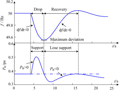
FIGURE 1. Effects of virtual inertia on system frequency.
Figure 1 shows that the output power Pv of the virtual inertia controller can only provide frequency support for the initial few seconds. Moreover, the negative power response is generated by the virtual inertia controller during the frequency recovery period. The main reasons for this phenomenon are: During the frequency recovery period (df/dt > 0), the power response of the virtual inertia ΔPv<0. At this stage, energy storage devices switch from releasing energy to absorbing energy. It absorbs power from the system under virtual inertia control. A part of the mechanical power issued by the primary frequency modulation of the synchronous generator is absorbed by the energy storage, and cannot be fully applied to the recovery of the synchronous speed, which increases the primary frequency modulation burden of the synchronous generator and causes the frequency recovery speed to slow down.
The other shortcoming of fixed inertia emulated by the VSG is that any inertia distribution changes also affect other transient characteristics, such as system damping. To estimate the impact of virtual inertia on system damping, the rotor motion equation of a SG is given by
Where ∆PG, DS and HS are the active power variation, damping coefficient and inherent inertia of the SG, respectively.
Under virtual inertia control, the rotor motion equation of the battery can be expressed similar to that of the SG as follows
where ∆PB and HBV are the storage energy and virtual inertia time constant of the battery, respectively.
The expression of the current variation ∆iB is given by ∆iB=(WBkB/uBω0)∆ω-iB. The small signal model of the battery can be expressed as
Using Eqs 15, 16, the state equation of the battery can be then written as
The state equation of the super capacitor can be obtained similarly. The state equation of the HESD can be written as
where ∆PES is the storage energy variation of the HESD, and WH, HHV, DH and kvir are the static energy, virtual inertia time constant, damping coefficient and SOC adjustment coefficient of the HESD, respectively. The last three terms are given as follows:
The rotor motion equation of a SG can be expressed as
Using Eqs 19, 20 and considering ∆δ, ∆ω and ∆PES as the state variables, the state equation of the power system with virtual inertia is obtained as
where the non-zero elements in the above matrix can be expressed as
It can be concluded based on (21) that the oscillation characteristics of the state variables are closely related to the virtual inertia of the HESD. To illustrate the effect of virtual inertia on system damping, the coefficient kvir is changed within the range [0, 20], and the eigenvalue root locus is shown in Figure 2. As can be observed, the root locus λ1 moves away from the imaginary axis of the state plane as kvir increases during the initial period. However, once kvir reaches a certain value, λ1 starts to move closer to the imaginary axis, which means that the system stability is reduced.
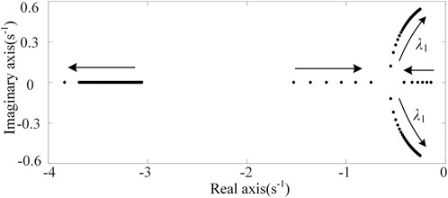
FIGURE 2. Root locus of eigenvalue with the change of inertia coefficient.
During the initial transient period, the system frequency change can be reduced with the increase of system inertia. However, subsequently, a larger inertia still prevents the frequency from recovering to the normal value, and as a result, the recovery time is increased. Moreover, the slower attenuation of the rotor angle of the SG causes it to oscillate unnecessarily.
The oscillation process of angular velocity and rotor angle of a SG after the application of a perturbation is shown in Figure 3. The oscillation period can be divided into two stages: 1) Phase A with ωS = ωe-ω0>0 and dδ/dt > 0, 2) Phase B with ωS = ωe-ω0<0 and dδ/dt < 0. As Figure 3 shows, the rotor angle δ increases during phase A. Increased inertia is useful for reducing the deviation of the rotor angle, and the system stability can be enhanced. However, if the power system enters phase B, the fixed inertia will prevent the rotor angle from going back to the initial value, resulting in a continuous oscillation.
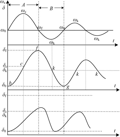
FIGURE 3. Power system oscillation process.
To address this issue, the virtual inertia is regulated in the proposed control scheme to transfer the transient energy from the SGs to HESDs during different oscillation stages of the rotor angle. The energy transfer controller of the frequency-coupled HESD is designed as
where Hv is the inertia coefficient of HESD with Hv>0, and ωS is the angular velocity deviation.
Under the proposed control scheme, the rotor motion equation of the power system can be expressed as follows:
Substituting (23) into (24), we get
Using the small disturbance analysis method, the linear equation is obtained as
The eigenequation of the system is obtained as
where HA = 2Hvωs0 is the inertia of the additional controller, and DA = Hv(dωs0/dt)2 is the damping of the controller.
During phase A, ωs0 > 0, and thus the positive inertia is provided by the proposed controller. The rotor angle will change slowly with the addition of virtual inertia. However, during phase B, ωs0 < 0, the virtual inertia is negative, and thus the rotor angle recovers quickly due to the decrease of system inertia. This new dynamic performance of the rotor angle is desirable for achieving system stability. In addition, the damping coefficient DA of the proposed controller is always positive. Thus, the controller can contribute to the improvement of the system damping characteristics.
To further verify the positive impact of the proposed control scheme on the system transient stability, the transient energy transfer between the SGs and HESDs is analyzed using the Lyapunov direct method. Figure 3 shows that both angular velocity ωe and rotor angle δ increase during phase A. If the fault is cleared in time at point c, the rotor angular velocity ω starts to decrease. However, it is still higher than the initial velocity ω0, and thus the rotor angle continues to increase. During phase B, both the angular velocity ω and rotor angle δ decrease before ωe returns to its initial value. After crossing the point k, ωe increases. However, δ decreases until ω returns to its initial value again.
The analysis of the dynamic performance of the rotor angle under the proposed control shows that a slower change and faster recovery of the rotor angle can be achieved during phases A and B, respectively. Obviously, during phase B, lower inertia will accelerate the recovery of the rotor angle. However, the oscillation amplitude and time increase during phase A due to the higher inertia. Therefore, it is imperative to analyze the transient energy change that takes place during phase A.
According to (24), under the proposed control scheme and ignoring the system damping, the transient energy of the power system can be expressed as
where ES is the inherent energy of SGs, EH is the additional energy generated by the energy transfer controller.
where δ0 is the initial value of the rotor angle, δc and δt are the rotor angles at fault clearing time and time t, respectively, δk is the rotor angle at the stable equilibrium point, and Pe2 and Pe3 are the electromagnetic powers before and after the fault is cleared, respectively.
According to (28), under the proposed control scheme, the system transient energy is composed of the inherent energy of the SGs and the additional energy generated by the energy transfer controller.
(1) During the fault period, the angular velocity and rotor angle are in the intervals [ω0,ωc] and [δ0,δc], respectively. In this period, the additional energy EHA generated by the energy transfer controller can be expressed as
During this accumulation phase of acceleration energy, the angular velocity increases, i.e (ωc-ω0)3 > 0, and dωS/dt>0. Consequently, the acceleration energy generated by the energy transfer controller satisfies EHA<0. Therefore, the energy transfer control can transfer the acceleration energy from the SG to the HESD and reduce the accumulation of acceleration energy.
(2) After the fault is cleared, the angular velocity and rotor angle are in the intervals [ωc,ωf] and [δc,δf], respectively. In this period, the additional energy EHD generated by the energy transfer controller can be expressed as follows:
During this transformation stage of deceleration energy, the angular velocity decreases, i.e (ωf-ω0)3-(ωc-ω0)3 < 0, and dωS/dt < 0. Consequently, the deceleration energy generated by the energy transfer controller satisfies EHD>0. Therefore, the HESD can be used to provide energy support and increase the conversion of deceleration energy under the energy transfer control.
It is obvious that under the proposed control strategy, the accumulation of acceleration energy decreases and the transformation of deceleration energy increases throughout phase A. According to the Lyapunov method, both the oscillation amplitude and time of the rotor angle can be reduced by sharing the transient energy between the SG and HESD. Thus, a stronger stability of the rotor angle can be achieved, thanks to the more efficient power control.
According to (6) and (11), the energy variation of HESD can be expressed as
The energy variation generated by energy transfer controller can be expressed as follows:
The relationship between virtual inertia of HESD and Hv can be expressed as
The structure of the HESD transient energy transfer controller is shown in Figure 4, in the control system, the variable upv and ipv are the reference voltage and reference current of the photovoltaic respectively; uabc* is the three-phase reference voltage for DC/AC converter pulse width modulation; udc* and udc are DC reference voltage and output voltage of DC/AC converter; id* and iq* are the reference current of the d and q axes of the DC/AC converter respectively; PES is the output power reference value of the HESD; iC is the output current of the supercapacitor; iB and iC are the current reference value of the storage battery and the supercapacitor respectively. As shown, four modules are added to the control system of HESD. According to (36), the virtual inertia of the battery and super capacitor is calculated to set the energy transfer control parameter Hv. The angular velocity signal is introduced to calculate the output power of the proposed controller Pv. After the fluctuation of PV is suppressed, the surplus power PES is then sent to the power distribution module. The inertia support is provided by the super capacitor at first after the power reference instruction is received. The remaining power difference (Pv–PC) is compensated by the energy stored in the battery to obtain the desired inertia response. The power provided by PV and HESD (Ppv + PES) flows into AC power grid through DC/AC converter, in which the voltage and current dual closed-loop control is adopted.
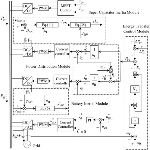
FIGURE 4. Flowchart of energy transfer control strategy.
Differential control is easy to generate high-frequency signals, resulting in a decrease in frequency quality and an increase in the probability of miss operation of the additional controller. Therefore, a first-order low-pass filter is set in the angular velocity detection link to filter out the high-frequency signal and eliminate its influence on the system frequency.
To demonstrate the effectiveness of the proposed control scheme, a test system is carried out, of which structure in shown in Figure 5. In the test system, the SGs and PV arrays are rated at 160 kVA and 100 kW, respectively. The HESD consists of a battery and a super-capacitor with capacities of 50 Ah and 10 F, respectively. The PV array and HESD were connected to the grid through bus B7, with loads L1 and L2 of 150 kW and 100 kW, respectively. The solar irradiance was set to 1000 W/m2.
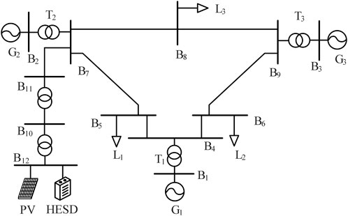
FIGURE 5. Structure of the experiment platform.
To illustrate the impact of energy transfer between the SGs and HESD on the system transient stability, the following three cases are considered. 1) Case A: without any additional control scheme. 2) Case B: VSG control scheme Ref. (Torres et al., 2014). 3) Case C: under the proposed control scheme in Figure 5 (kB = 0.1, kC = 0.2, Hv = 5.6).
Due to the duration of common power disturbances, such as generator cut-off, high-power load switching, and other events, is much longer than the time required for inertial support. Therefore, this paper treats ΔPd as a step signal, and conservatively evaluates controller performance regardless of the disturbance duration. To illustrate the performance of the proposed control scheme for system frequency, load L1 is increased by 50 kW at 18s. Experimental results of the system frequency f, output active power PG of SG1, and output active power PE of HESD in cases A-C are compared in Figures 6A–C. In the simulation model, the synchronous generator contains primary and secondary frequency regulation modules, which are close to the frequency regulation mode of the actual power grid. Among them, the primary frequency adjustment is differential regulation, and the secondary frequency adjustment is non-differential regulation. When the synchronous generator starts the secondary frequency regulation, the frequency of the system under situation A-C can be restored to 50 Hz.

FIGURE 6. Dynamic system responses after sudden load variation.
In case A, the system frequency performance during the initial period mainly depends on the inherent inertia of the SGs. However, among all three cases, the largest frequency drop of around 0.5 Hz is observed for Case A due to the lowest inertia, as shown in Figure 6A. Since the synchronous generator equips a secondary frequency regulator in the simulation system, which contains the PI controller. Thus, in the dynamic process, the inevitable overshoot of the system frequency can be observed. In all three cases, the overshoot of case A was observed to be the largest since case A had the lowest damping.
In case B, virtual inertia is provided by the HESD under the VSG by detecting the frequency variation. As shown, the frequency deviation is reduced to around 0.25 Hz. Before the system frequency drops to its minimum value, the positive power support is generated by the VSG, and thus the rate of change of system frequency is reduced with the addition of virtual inertia. However, once the system frequency begins to recover, the HESD still prevents the frequency from going back to its normal value, and the active power generated by the VSG is negative for the increased load. Thus, a slower system frequency recovery is observed.
In case C, under the proposed control scheme, the rate of change of the frequency drop is reduced similar to that in case B. More importantly, the best system frequency recovery performance is attained because the HESD always maintains a positive power support to share the load demand with the SGs. Thus, the recovery period of system frequency is the shortest for case C among all three cases.
(a) Case A: without additional control (b) Case B: VSG control (c) Case C: under the proposed control
To illustrate the performance of the proposed control scheme on system damping, a 0.1s three phase short-circuit fault is applied on bus B9 at 18s. The experimental results of the rotor angle δ, system frequency f, angular velocity ω, tie-line transmission power PT, output active power PE and output active power PG of SG1 for cases A–C are compared in Figures 7A–C.
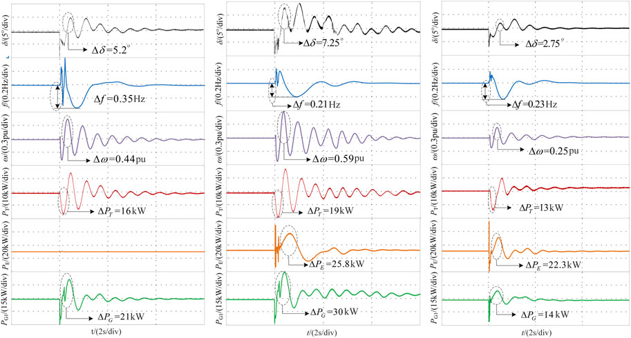
FIGURE 7. Dynamic system responses after short-circuit fault.
As Figure 7A shows, a continuous rotor angle oscillation can be observed in the absence of any additional control. Although the power system stabilizers are applied to the SGs in the test system, the system damping is still insufficient. In the test system with a high penetration of PV generation, there is still a lack of regulators. Obviously, the ability of HESDs to dampen the oscillation is important.
However, in case B, the virtual inertia is provided by the HESD. Although the frequency stability can be improved as verified in Section 5.2 (case B), an unexpected rotor angle oscillation is likely to be caused by the addition of virtual inertia. As Figure 7B shows, the maximum swing amplitude of the rotor angle is increased from 5.2° to 7.25°. Compared with case A, a more serious oscillation of the rotor angle is observed. Moreover, it is harder for the SGs to damp the oscillations of ω, PT and PG. The main reason for this phenomenon is that during different oscillation phases of the rotor angle, the frequency coupled HESD with a constant inertia produces a negative damping effect.
In case C, as Figure 7C illustrates, the oscillation amplitude of δ is reduced to around 2.75°, and the oscillation durations of δ, ω, PT and PG are shortened to 3.2 s. Obviously, the proposed control scheme improves the system transient stability. The test results demonstrate that the transient energy transfer between the SGs and HESD is beneficial for increasing the system damping.
In this paper, the energy source of rotational inertia is expanded to static HESDs for improving the frequency stability of power systems with renewable power generation. Moreover, this paper proposes a new energy transfer control strategy for frequency-coupled HESD based on transient stability analysis. Different from the traditional additional inertia or damping control, the controller presented here provides different virtual inertia at different oscillation stages, and the strategy always has a positive additional damping coefficient throughout the frequency recovery process, which helps to improve the damping characteristics of the system. The main conclusions of this study are as follows.
1) By analyzing the conversion relationship between the static energy of HESD and mechanical kinetic energy of SG, the virtual inertias of battery and capacitor are defined respectively. The frequency-coupled HESD can provide virtual inertia response for dynamic frequency support. However, the fixed virtual inertia of HESDs can negatively affect the rotor angle, and even lead to system instability.
2) In transient events, the frequency-coupled HESD can reduce the rate of change of system frequency before the frequency reaches its minimum value. However, after the initial period, a slower frequency recovery is caused by the HESD if the virtual inertia remained constant. Based on the analysis and test results, it can be concluded that the negative damping effect is caused by the addition of constant virtual inertia, which consequently leads to the unexpected rotor angle oscillation. Thus, the wide application of frequency-coupled HESD cannot be achieved because of the reduced transient stability of the rotor angle.
3) To reduce the application risk of frequency-coupled HESD for system transient stability, a novel energy transfer control scheme is proposed. During the initial oscillation phase, the HESD prevents the rotor angle from changing by increasing the system inertia. If the rotor angle reaches its maximum value, a negative virtual inertia is produced that accelerated the rotor angle recovery to a stable value due to the lower inertia. Throughout the oscillation period, the energy transfer between the SGs and HESDs is achieved by the proposed controller, and thus the transient energy of the SGs always decreased. According to the Lyapunov stability criterion, the system transient stability is improved. As evident from theoretical analysis and test results, the HESD has the new ability to provide more reliable support to system.
The original contributions presented in the study are included in the article/Supplementary material, further inquiries can be directed to the corresponding author.
Conceptualization, ZF, WL, BZ, and WB; data curation, WB and YC; formal analysis, ZF; funding acquisition, WL; methodology, ZF, WL, BZ, and ZZ; project administration, ZF; supervision, WL; validation, WL, WB, BC, and YC; visualization, ZZ; writing—review and editing, WL, ZZ, and BC. All authors contributed to the article and approved the submitted version.
This research was funded by 2022 Science and Technology Project of State Grid Gansu Electric Power Company, grant number 522730220003.
The authors gratefully acknowledge financial support from the 2022 Science and Technology Project of State Grid Gansu Electric Power Company (522730220003).
ZF, WL, WB, ZZ, BC, and YC were employed by Economic and Technological Research Institute of State Grid Gansu Electric Power Company.
The remaining author declares that the research was conducted in the absence of any commercial or financial relationships that could be construed as a potential conflict of interest.
All claims expressed in this article are solely those of the authors and do not necessarily represent those of their affiliated organizations, or those of the publisher, the editors and the reviewers. Any product that may be evaluated in this article, or claim that may be made by its manufacturer, is not guaranteed or endorsed by the publisher.
Alipoor, J., Miura, Y., and Ise, T., "Distributed generation grid integration using virtual synchronous generator with adoptive virtual inertia," 2013 IEEE Energy Conversion Congress and Exposition, Denver, CO. 4546
Alipoor, J., Miura, Y., and Ise, T. (2015). Power system stabilization using virtual synchronous generator with alternating moment of inertia. IEEE J. Emerg. Sel. Top. Power Electron. 3 (2), 451–458. doi:10.1109/jestpe.2014.2362530
Alipoor, J., Miura, Y., and Ise, T. (2018). Stability assessment and optimization methods for microgrid with multiple VSG units. IEEE Trans. Smart Grid 9 (2), 1462–1471. doi:10.1109/tsg.2016.2592508
Cheema, K. M., and Mehmood, K. (2020). Improved virtual synchronous generator control to analyse and enhance the transient stability of microgrid. IET Renew. Power Gener. 14 (4), 495–505. doi:10.1049/iet-rpg.2019.0855
Hammad, E., Farraj, A., and Kundur, D. (2019). On effective virtual inertia of storage-based distributed control for transient stability. IEEE Trans. Smart Grid 10 (1), 327–336. doi:10.1109/tsg.2017.2738633
Li, D., Zhu, Q., Lin, S., and Bian, X. Y. (2017). A Self-adaptive inertia and damping combination control of VSG to support frequency stability. IEEE Trans. Energy Conver. 32 (1), 397–398. doi:10.1109/tec.2016.2623982
Li, M., Huang, W., Tai, N., Yang, L., Duan, D., and Ma, Z. (2020). A dual-adaptivity inertia control strategy for virtual synchronous generator. IEEE Trans. Power Syst. 35 (1), 594–604. doi:10.1109/tpwrs.2019.2935325
Ma, J., Qiu, Y., Li, Y., Zhang, W., Song, Z., and Thorp, J. S. (2017). Research on the impact of DFIG virtual inertia control on power system small-signal stability considering the phase-locked loop. IEEE Trans. Power Syst. 32 (3), 2094–2105. doi:10.1109/tpwrs.2016.2594781
Song, W., Wang, L., Zhao, W., Zhang, X., and Wang, Z. (2022). Inertia optimization control and transient stability analysis of wind power grid-connected system. Front. Energy Res. 10 (21). doi:10.3389/fenrg.2022.939468
Torres, M. A. L., Lopes, L. A. C., Morán, L. A. T., and Espinoza C., J. R. (2014). Self-tuning virtual synchronous machine: A control strategy for energy storage systems to support dynamic frequency control. IEEE Trans. Energy Conver. 29 (4), 833–840. doi:10.1109/tec.2014.2362577
Wang, Y., Meng, J., Zhang, X., and Xu, L. (2015). Control of PMSG-based wind turbines for system inertial response and power oscillation damping. IEEE Trans. Sustain. Energy 6 (2), 565–574. doi:10.1109/tste.2015.2394363
Xiong, L., Li, P., Wu, F., and Wang, J. (2019). Stability enhancement of power systems with high DFIG-wind turbine penetration via virtual inertia planning. IEEE Trans. Power Syst. 34 (2), 1352–1361. doi:10.1109/tpwrs.2018.2869925
Xiong, L., Liu, L., Liu, X., and Liu, Y. (2021b). Frequency trajectory planning based strategy for improving frequency stability of droop-controlled inverter based standalone power systems. IEEE J. Emerg. Sel. Top. Circuits Syst. 11 (1), 176–187. doi:10.1109/jetcas.2021.3052006
Xiong, L., Liu, X., Liu, Y., and Zhuo, F. (2022). Modeling and stability issues of voltage-source converter dominated power systems: A review. CSEE J. Power Energy Syst. 8 (6), 1530–1549. doi:10.17775/cseejpes.2020.03590
Xiong, L., Liu, X., Zhang, D., and Liu, Y. (2021a). Rapid power compensation based frequency response strategy for low inertia power systems. IEEE J. Emerg. Sel. Top. Power Electron. 9 (4), 4500–4513. doi:10.1109/jestpe.2020.3032063
Yang, D., Wang, X., Chen, W., Yan, G., Jin, Z., Jin, E., et al. (2023b). Adaptive frequency droop feedback control-based power tracking operation of a DFIG for temporary frequency regulation. IEEE Trans. Power Syst. 10, 1–10. doi:10.1109/tpwrs.2023.3277009
Yang, D., Wang, X., Yan, G., Jin, E., Huang, J., Zheng, T., et al. (2023a). Decoupling active power control scheme of doubly-fed induction generator for providing virtual inertial response. Int. J. Electr. Power and Energy Syst. 149, 109051–109110. doi:10.1016/j.ijepes.2023.109051
Ying, J., Yuan, X., Hu, J., and He, W. (2018). Impact of inertia control of DFIG-based WT on electromechanical oscillation damping of SG. IEEE Trans. Power Syst. 33 (3), 3450–3459. doi:10.1109/tpwrs.2018.2801283
You, F., Si, X., Dong, R., Lin, D., Xu, Y., and Xu, Y. (2022). A state-of-charge-based flexible synthetic inertial control strategy of battery energy storage systems. Front. Energy Res. 10 (25). doi:10.3389/fenrg.2022.908361
Zhang, W., Remon, D., and Rodriguez, P. (2017). Frequency support characteristics of grid-interactive power converters based on the synchronous power controller. IET Renew. Power Gener. 11 (4), 470–479. doi:10.1049/iet-rpg.2016.0557
Zhang, X., Zhu, Z., Fu, Y., and Li, L. (2020a). Optimized virtual inertia of wind turbine for rotor angle stability in interconnected power systems. Electr. Power Syst. Res. 180, 106157. doi:10.1016/j.epsr.2019.106157
Zhang, X., Zhu, Z., Fu, Y., and Shen, W. (2020b). Multi-objective virtual inertia control of renewable power generator for transient stability improvement in interconnected power system. Int. J. Electr. Power and Energy Syst. 117, 105641. doi:10.1016/j.ijepes.2019.105641
Zhao, F., Shuai, Z., Shen, C., Cheng, H., Shen, Y., and Peng, Y. (2020). Comparison of transient angle stability between virtual synchronous generator and droop-controlled inverter, 2020. New Orleans, LA, USA: IEEE APEC, 2308–2312.
Zhong, Q., Nguyen, P., Ma, Z., and Sheng, W. (2014). Self-synchronized synchronverters: Inverters without a dedicated synchronization unit. IEEE Trans. Power Electron. 29 (2), 617–630. doi:10.1109/tpel.2013.2258684
Keywords: hybrid energy storage, virtual inertia, rotor angle, frequency stability, energy transfer
Citation: Feng Z, Li W, Bai W, Zhang B, Zhang Z, Chen B and Cui Y (2023) Transient energy transfer control of frequency-coupled energy storage devices in low inertia prosumer energy systems. Front. Energy Res. 11:1235645. doi: 10.3389/fenrg.2023.1235645
Received: 06 June 2023; Accepted: 19 July 2023;
Published: 31 July 2023.
Edited by:
Liansong Xiong, Xi’an Jiaotong University, ChinaReviewed by:
Huimin Wang, Zhejiang Sci-Tech University, ChinaCopyright © 2023 Feng, Li, Bai, Zhang, Zhang, Chen and Cui. This is an open-access article distributed under the terms of the Creative Commons Attribution License (CC BY). The use, distribution or reproduction in other forums is permitted, provided the original author(s) and the copyright owner(s) are credited and that the original publication in this journal is cited, in accordance with accepted academic practice. No use, distribution or reproduction is permitted which does not comply with these terms.
*Correspondence: Wanwei Li, ODU4NzEwMjIzQHFxLmNvbQ==
Disclaimer: All claims expressed in this article are solely those of the authors and do not necessarily represent those of their affiliated organizations, or those of the publisher, the editors and the reviewers. Any product that may be evaluated in this article or claim that may be made by its manufacturer is not guaranteed or endorsed by the publisher.
Research integrity at Frontiers
Learn more about the work of our research integrity team to safeguard the quality of each article we publish.