 Zhi Zhang
 Yiyun Li
 Caomao Zhong1
- 1Department of Electrical Engineering and Automation, Dongguan University of Technology, Dongguan, China
- 2College of Mechatronics and Control Engineering, Shenzhen University, Shenzhen, China
The three-phase voltage-source grid-connected inverters suffer from grid-connected current quality problems due to system resonance caused by the under-damping characteristics of the filter and grid impedance, on the one hand, and the grid-connected current distortion caused by the high content of low harmonics in the grid voltage, on the other hand. To resolve this problem, a current quality improvement control strategy, combining capacitor-current feedforward active damping and harmonic virtual impedance reshaping, is proposed by analyzing the mechanisms of system resonance and grid-connected current distortion. In addition, the proposed control strategy allows determining the virtual impedance parameters by using the root locus method, so as to achieve the purpose of improving the output grid-connected current quality of the three-phase voltage-source grid-connected inverter under weak grid conditions. Finally, the correctness and effectiveness of the proposed control strategy are verified by simulation and experiment.
1 Introduction
With the rapid development of renewable energy by power generation technologies, the variety of power generation equipment used in the grid is rapidly increasing, and the installed capacity of distributed generating units is also increasing. As a medium, the grid-connected inverter connects the distributed power generation system to the grid. Grid-connected inverters are required to ensure the safe and stable operation of the grid while integrating renewable energy generation into the grid and to provide stable voltage and frequency support for the grid. Virtual synchronous generator (VSG) technology (Koiwa et al., 2022) simulates the external characteristics of a conventional synchronous generator, which provides inertia and damping characteristics for the grid-connected inverter to regulate the grid voltage and frequency. However, since distributed generation systems are geographically dispersed (Fang et al., 2018; Mohammed et al., 2023) and usually require long-distance transmission lines to connect them to the public grid, the line equivalent impedance of distributed generation systems is large, the grid impedance (Zhou et al., 2017; Li et al., 2020; Tang et al., 2021) is not negligible, the grid voltage tends to fluctuate, and the grid thus exhibits weak grid characteristics (Zhao et al., 2022; Mohammed et al., 2023). According to the IEEE 1204–1997 standard (IEEE, 1997), the grid short-circuit ratio (SCR: the ratio of the short-circuit capacity to the nominal capacity of the system) is between 2 and 3 in the weak grid. Under a weak grid, the grid-connected inverter stability is more easily affected by the line impedance, and when the harmonic content in the grid voltage is high, the harmonic voltage will introduce the harmonic current into the grid through the line impedance (Knenicky et al., 2021), which significantly affects the quality of the grid-connected current output.
In terms of structure, a three-phase voltage-source grid-connected inverter with LC filters under a weak grid will form the LCL filter structure with grid-side line impedance. Although the LCL filter can provide a better harmonic attenuation effect on the system in the high-frequency band while maintaining a better amplitude and frequency gain in the low-frequency band, the formed LCL filter will introduce a high-frequency resonance into the system due to its own inherent frequency characteristics (Stojić and Šekara, 2022). The existence of this resonant spike easily leads to the oscillation of the inverter output grid current, which causes the poor stability of the system. When the non-linear load (Vijay and Doolla, 2021) connected to the grid increases, the harmonic content of the grid voltage will increase significantly, which will cause significant distortion of the inverter output grid-connected current (Lin et al., 2020; Zhong et al., 2021), thus failing to meet the requirements of the grid-connected standard. Both unfavorable factors will have a significant negative impact on the stable operation of the grid, which may lead to the inability of the three-phase voltage-source grid-connected inverter to connect to the grid and may even lead to grid collapse. Therefore, the study of inverter resonance suppression and grid-connected output current quality improvement control strategies has received considerable attention.
In this paper, the control structure of a three-phase voltage-source grid-connected inverter is modeled and analyzed as the main research subject. The resonance suppression scheme of the capacitor-current feedforward is studied to solve the grid-connected current oscillation problem of the grid-connected inverter under the weak grid condition. In view of the grid-connected current distortion problem caused by the high content of low harmonics (5th and 7th harmonics) in the grid voltage, the harmonic suppression scheme is discussed, and the stability analysis of the adopted harmonic virtual impedance scheme is carried out to reasonably set the virtual impedance parameter values. By combining capacitor-current feedforward and harmonic virtual impedance control strategy based on impedance reshaping, the purpose of grid-connected current quality improvement under weak grid conditions can be achieved. The remainder of this paper is organized as follows: in Section 2, the filter selection of the three-phase voltage-source grid-connected inverter is analyzed, the mathematical model is constructed, and the modules included in the overall control block diagram are introduced. In Section 3, the resonance mechanism of the grid-connected inverter is analyzed, and a resonance suppression control strategy is proposed. In Section 4, the mechanism of the distortion from the grid-connected inverter output current is analyzed, and a harmonic virtual impedance control strategy is proposed to improve the output grid-connected current quality. In Section 5, the simulation and experimental analysis process are provided. Finally, in Section 6, conclusion is reported.
2 Modeling of the three-phase voltage-source grid-connected inverter system
Three-phase voltage-source grid-connected inverters, as an important interface between renewable energy distributed power generation systems and the grid, have become an indispensable part of distributed power generation systems (Liu T. et al., 2019; Guo et al., 2019; Han et al., 2019), which can play a role in converting electricity and connecting distributed power generation units to the grid. The topology, filter design, and controller design of the three-phase grid-connected inverter are important for improving the quality of the grid-connected current output and operation stability, which also remains the focus of extensive academic research.
In terms of topology selection, the three-phase two-level voltage-source grid-connected inverter is widely used in actual engineering projects. However, the grid-connected inverter will introduce a large number of harmonics at the switching frequency to the grid through pulse width modulation. Therefore, the structure of the grid-connected inverter must be reasonably designed. The filter is a key link to ensure that the inverter output grid-connected current quality meets the total harmonic distortion content index (Lai and Kim, 2017) within the specified range. The IEEE 1547–2003 standard (IEEE, 2003) stipulates that the total harmonic distortion (THD) of the output grid-connected current should be less than 5%.
At present, the most widely used filters are the L filter, LC filter, and LCL filter (Dursun and DÖŞOĞLU, 2018; Mondal et al., 2018; Karbasforooshan and Monfared, 2022). These three filters have their own advantages and disadvantages. The L filter can filter out the high-frequency harmonic signal by using the large impedance characteristic of the inductor at high frequencies. Its structure is simple, and it belongs to the first-order circuit. It will not introduce resonance into the system, and the effect of suppressing harmonics at the switching frequency is obvious. However, its dynamic performance is poor, the equipment volume is large, and its economic performance is poor. To improve the energy conversion efficiency, the impedance of the filter needs to be as small as possible to reduce the loss of the electric energy on the filter; thus, the filter must have better attenuation characteristics in the high-frequency band. Obviously, the limitations of the L filter in this regard restrict its scope of use. The LC filter, which can filter out the harmonics of a specific frequency, is a filter circuit composed of an inductor and a capacitor (Li et al., 2015). It has a simple structure and low cost and can effectively attenuate the high-frequency harmonic components of the output voltage in the independent mode. However, due to undamped or underdamped traditional LC filters, large oscillations are easily generated at the output of the filter, which will also cause electromagnetic interference (EMI) problems caused by the strong pulse state of the output current. The LCL filter is a filter circuit composed of two inductors and a capacitor. Its schematic structure is shown in Figure 1.
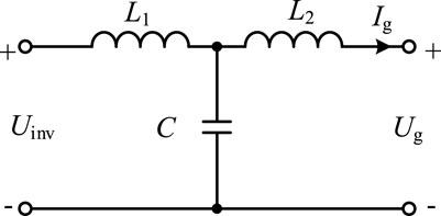
FIGURE 1. Schematic structure of the LCL filter.
It can effectively improve the attenuation characteristics of the filter in the high-frequency band while maintaining better gain characteristics in the low-frequency band. When the high-frequency harmonic signal is input, since the impedance of the filter capacitor branch decreases with increasing ω, the filter capacitor branch will provide a low-impedance path for high-frequency harmonics, while the filter inductor branch presents high impedance, thus performing parallel impedance shunting, which will further suppress the injection of high-frequency harmonic current components into the grid. The filtering performance of the LCL filter has greatly improved by virtue of its high attenuation rate in the high-frequency band, improving the quality of the grid-connected current. Under the same filtering effect, the inductance value of the LCL filter is smaller than that of the L filter, which can significantly reduce equipment cost and size. In a weak grid system, it is generally considered that the grid-side line impedance is an inductive load (Jin et al., 2018); in other words, the grid-side line presents inductive characteristics. Therefore, when considering the line impedance of the grid side, it can also be approximately considered that the LC filter is the same as the LCL filter.
Considering the state of inductive characteristics on the grid side, an LC filter is inserted between the inverter and the grid to form an LCL filter with a line impedance to suppress higher harmonics in the output current of the grid-connected inverter. The topology of the three-phase voltage-source grid-connected inverter with the LC filter is shown in Figure 2A, where L1 and C are the adopted LC filter structure, and the LCL filter structure is formed by combining the grid-side inductor Lg, so it is analyzed as an LCL filter. The LCL filter can provide better gain for the system in the low-frequency band and can attenuate the high-frequency signal in the high-frequency band to produce a good filtering effect.
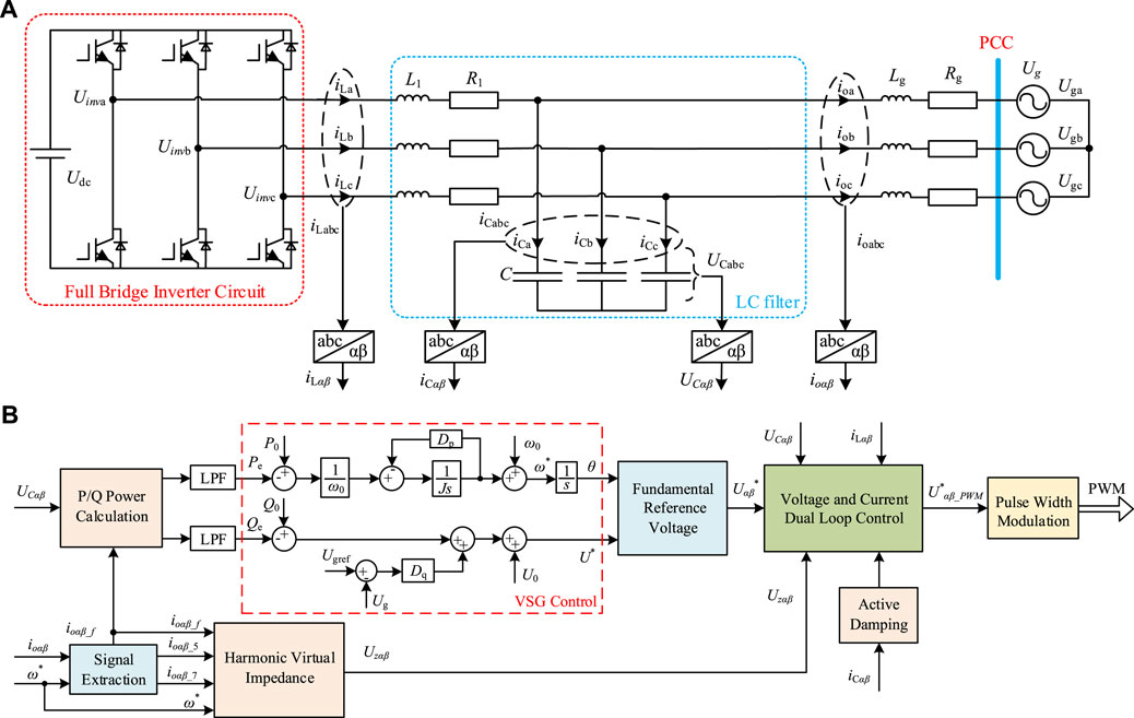
FIGURE 2. Three-phase voltage-source grid-connected inverter topology and overall control block diagram: (A) three-phase voltage-source grid-connected inverter topology; (B) overall control block diagram.
According to the three-phase voltage-source grid-connected inverter topology shown in Figure 2A, the state differential equation between each voltage and current in the system can be obtained using Kirchhoff’s voltage–current law, as shown in Eqs 1–3.
Figure 2B shows the overall control block diagram of the system in the αβ coordinate system, which contains the signal separation and extraction module, power calculation module, VSG control structure (Lou et al., 2021), voltage and current dual-loop control module, and active damping and harmonic virtual impedance modules proposed in this paper. Among them, Pe and Qe are the instantaneous active and reactive power obtained by the power calculation module through the low-pass filter (LPF), the reference voltage for the voltage–current double-loop control is obtained through the VSG control, the pulse-width modulated signal is obtained through the voltage–current dual loop control, and finally, the control signal of the three-phase voltage-source grid-connected inverter is obtained through the pulse-width modulation.
3 Resonance mechanism and resonance suppression control strategy of the grid-connected inverter
3.1 Resonance mechanism of the grid-connected inverter
The line impedance on the grid side of the three-phase voltage-source grid-connected inverter under a weak grid shows inductance, and the LC filter taken in the topology will form an LCL filter with the line impedance. When the parasitic resistance R1 of the filter inductor L1 and the resistive component Rg in the line impedance are neglected and the inductor Lg in the grid-side line impedance is equated to the inverter side, the single-phase s-domain circuit equivalent model of the three-phase two-level voltage-source grid-connected inverter topology shown in Figure 2A can be reduced to the structure shown in Figure 3A. The equivalent model of the circuit, as shown in Figure 3A, can be reduced to the Thevenin’s equivalent circuit, as shown in Figure 3B, by using the Thevenin’s equivalence principle.
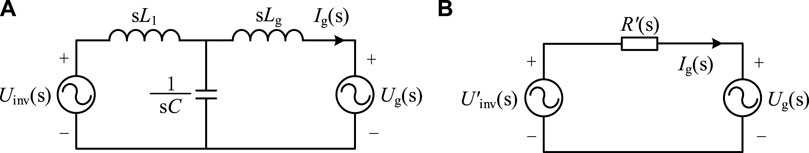
FIGURE 3. Circuit equivalent model: (A) circuit equivalent model of the LCL filter s domain; (B) Thevenin’s equivalent circuit of the LCL filter.
In Figure 3B, R′ is the Thevenin’s equivalent impedance and U′inv is the Thevenin’s equivalent input, both of which can be expressed using Eqs 4, 5, respectively.
Equations 4, 5 can be simplified to obtain the input‒output characteristic transfer function of the LCL filter link formed in the three-phase voltage-source grid-connected inverter, as shown in Eq. 6:
Eq. 6 shows that the LCL filter is a complex third-order system (Guan et al., 2018), containing only s3 and s terms and lacking damping, which will also lead to the existence of resonant pole points in the system, thus exhibiting higher-order resonance phenomena. The amplitude–frequency characteristic curves and the phase–frequency characteristic curves of the Bode plot of the LCL filter’s input–output characteristic also intuitively and clearly reflect this problem. The experimental parameters L1 and C and the estimated line impedance inductance Lg are substituted into Eq. 6 and represented as the Bode diagram, as shown in Figure 4.
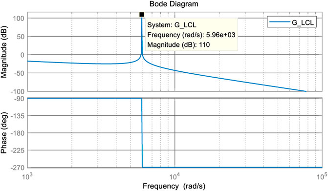
FIGURE 4. Bode diagram of the LCL filter input‒output transfer function.
The input and output amplitude–frequency characteristic curves of the LCL filter, as shown in Figure 4, imply that the grid-connected inverter filtered by introducing the LC filter constituting the LCL filter exhibits excellent harmonic attenuation characteristics in the high-frequency band, which can significantly reduce the low harmonic currents in the system. However, due to the lack of a damping term, the LCL filter will lead to a high resonant spike in the high-frequency band of the grid-connected inverter, the corresponding angular frequency ωr at the resonant spike is called the resonant angular frequency, and the magnitude of the resonant angular frequency can be calculated using Eq. 7.
In addition, it can be seen from the figure that the phase–frequency characteristic of the system has a phase jump of −180° at the resonant frequency point, so that the system phase crosses the −180° divider. This means that the system will produce a pair of closed-loop poles in the right plane of s. At this time, if the amplitude–frequency characteristic curve at the resonant corner frequency cannot be limited to below 0 dB, it will cause the oscillation of the grid-connected inverter system (Ma et al., 2021), which will have an impact on the system stability. Therefore, additional control strategies are needed to suppress grid-connected inverter resonances, and the active damping (Zhu et al., 2019; Zhang et al., 2020; Dang et al., 2021; Zeng et al., 2021) control strategy with additional control algorithms can provide damping for the system, suppress system resonances, and improve system stability effectively.
3.2 Active damping control strategy
Active damping control actively suppresses resonant spikes by introducing state variable feedback at the control level, while different categories of active damping control can be classified according to the amount of state feedback. Examples include active damping control with filter capacitor voltage feedback proposed in Zhang et al. (2020), active damping control with filter capacitor current proportional feedback proposed in Dang et al. (2021), active damping control with grid-side grid current feedback proposed in Zhu et al. (2019), and active damping control strategy with grid-side voltage feedback proposed in Zeng et al. (2021). All these approaches can effectively suppress resonant spikes, and among the various active damping control schemes, filter capacitor current proportional feedback (CCF) active damping control has the least impact on the filtering performance (Zhang et al., 2016; Aapro et al., 2017; Li and Lin, 2021) and can achieve a better resonance suppression effect; thus, it is widely used in the industry.
3.2.1 Control modeling of the three-phase voltage-source grid-connected inverter
Generally, the control structure of the three-phase voltage-source grid-connected inverter is in the form of a cascade, so the voltage–current double closed-loop control model can be constructed, as shown in Figure 5.
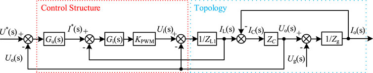
FIGURE 5. Three-phase voltage-source grid-connected inverter voltage–current dual-loop equivalent model.
Among them, Gu(s) in the control link is the voltage external loop controller, which usually adopts proportional integral (PI), proportional resonance (PR) control, or quasi-proportional resonance (QPR) control to track the voltage reference output by the VSG. In actual engineering applications, the harmonic components with the most content in the grid voltage are the 5th and 7th harmonics. Therefore, in this paper, the QPR is selected with the compensation of the 5th and 7th harmonic component controllers to track the nominal voltage in the stationary αβ coordinate system, the transfer function of the controller Gu(s) in this case is shown in Eq. 8.
where kp is the proportional gain, kf is the resonant gain at the fundamental frequency, kh is the resonant gain at the harmonic frequency, ωc is the bandwidth of the controller, ω0 is the voltage fundamental angular frequency, and h indicates the signal frequency.
The inner-loop current-loop controller Gi(s) is used to track the current reference, which is designed as the proportional (P) control in this paper. Moreover, KPWM is the inverter equivalent gain because the modulation part uses SVPWM, so KPWM = 1. The topology part is determined by its own structure, as shown in Figure 2A, ZL1 = sL1 + R1, ZC = 1/(sC), and Zg = sLg + Rg, while the grid voltage Ug(s) is treated as a disturbance quantity in the modeling. In the equivalent model, the voltage reference U*(s) of the outer voltage loop is derived from the nominal voltage of the VSG control output, and the input of the voltage loop is adjusted by PI or PR to obtain the current reference I*(s) of the inner current loop, which is then controlled by the inner loop to obtain the modulating signal.
According to Figure 5, the transfer function relationship between the reference voltage U*(s) and the inverter output voltage Uo(s) and output current Io(s) is described in Eq. 9.
where Go(s) and Zo(s) are expressed as shown in the following equations:
According to Eq. 9, the grid-connected inverter can be equated to an ideal voltage source Go(s)U*(s) and its output impedance Zo(s) in series, while the weak grid can also be equated to a voltage source Ug(s) and grid impedance Zg(s) in series, thus obtaining the equivalent circuit of the grid-connected system, as shown in Figure 6.

FIGURE 6. Equivalent circuit of the grid-connected system.
The following relationship between the output current Io(s) and the output voltage Uo(s), the grid voltage Ug(s), and the grid impedance Zg(s) can be obtained from Figures 5, 6.
Combining Eqs 9–12, we can obtain the expression of the grid-connected output current Io(s) transfer function as
where G(s) is the inverter conductance and Z(s) is the grid equivalent output conductance, as shown in Eqs 14, 15, respectively.
From Eq. 13, it is realized that the output grid-connected current Io(s) is composed of two parts: one part is generated by the input reference voltage U*(s) through the inverter conductance G(s), which is the main component of the grid-connected output current; the other part is obtained by the grid voltage Ug(s) through the grid conductance Z(s), which is regarded as a disturbance variable.
3.2.2 Design of the active damping parameters for capacitive-current proportional feedforward
The capacitive-current proportional feedforward active damping control is a control strategy that compensates for the control signal by feeding forward the filter capacitor-current as a state variable in the voltage–current dual loop control, thus achieving active suppression of the filter resonance in the voltage source inverter. The overall control block diagram, as shown in Figure 2B, also reflects that the capacitor-current proportional feedforward active damping control strategy is implemented in the control session of the voltage–current dual loop, and the voltage–current dual loop equivalent model with the introduction of the capacitor-current proportional feedforward active damping control is shown in Figure 7A.
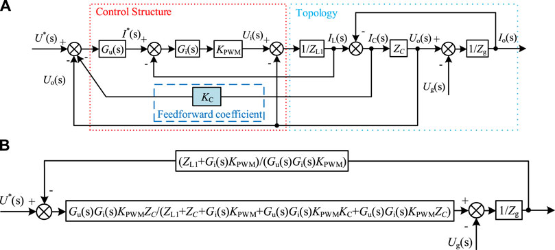
FIGURE 7. Voltage–current dual closed-loop equivalent model of a three-phase voltage-source grid-connected inverter with the capacitor-current proportional feedforward: (A) original equivalent model; (B) simplified equivalent model.
After the introduction of capacitor-current proportional feedforward, the control structure will be changed, which will also lead to a change in the inverter conductance G(s) and grid conductance Z(s). Moreover, the changed inverter conductance and grid conductance can be expressed using Eqs 16, 17, respectively. This change effectively suppresses the LCL filter resonance.
The key to resonance suppression by capacitive-current proportional feedforward active damping control is reasonably designing the value of the feedforward coefficient KC. The introduction of the feedforward coefficient KC must meet the prerequisite of ensuring system stability, so it is necessary to determine the value range of the feedforward coefficient KC to ensure system stability and select the optimal feedforward coefficient from it.
By shifting the lead-in and comparison points, the three-phase voltage-source grid-connected inverter voltage–current dual closed-loop equivalent model with proportional feedforward of the capacitor and current, as shown in Figure 7A, can be reduced to the single-loop form, as shown in Figure 7B
The open-loop transfer function between the reference voltage U*(s) and the output current Io(s) can be obtained from the simplified equivalent model, as shown in Eq. 18.
The Bode diagram of the open-loop transfer function of the system with different values of the capacitor-current feedforward coefficient KC can be plotted according to Eq. 18, as shown in Figure 8.
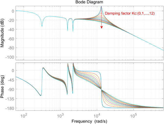
FIGURE 8. Open-loop transfer function Bode diagram with different values of the feedforward coefficient KC.
Figure 8 shows the effect of different values of the feedforward coefficient KC on the amplitude–frequency and phase–frequency characteristics of the system input and output open-loop transfer functions. When the capacitor-current feedforward coefficient KC is set to 0, the system does not adopt any resonance suppression control strategy. Thus, a significant resonance spike in the amplitude–frequency characteristic curve of the open-loop transfer function occurs at the resonant frequency angle, and the existence of this resonance will cause the output grid-connected current to oscillate. The Bode plot analysis shows that the resonant spike of the system is effectively suppressed after the introduction of the capacitor current feedforward control, and the suppression effect of the resonant spike is more significant with an increasing value of the feedforward coefficient KC. In addition, KC has no effect on the amplitude–frequency characteristics of the system in the low- and high-frequency bands. However, with an increasing KC, the gain of the system at the resonant frequency gradually decreases, which leads to a reduction in the system bandwidth and increase in the phase lag of the system. Therefore, the system bandwidth and phase difference requirements need to be considered when selecting the appropriate feedforward coefficient KC.
Active damping control can solve the system resonance problem caused by the LCL filter’s own underdamping and improve the system stability and output grid-connected current quality to a certain extent. However, when the output grid-connected current is distorted due to the high content of low harmonics in the grid voltage, the active damping control strategy cannot meet the requirement of improving the output grid-connected current quality. Therefore, it is necessary to combine some additional control strategies to improve the quality of the grid-connected current output. The grid voltage full-feedforward proposed in Wang et al. (2010) can achieve the complete decoupling of the current loop and grid-connected voltage, but the primary and secondary differentiation links existing in the full-feedforward function easily amplify the high-frequency signal disturbance, which leads to system instability. Moreover, the grid voltage proportional feedforward approach is too weak to suppress the current harmonics and is only applicable to the cases where the harmonic components are lower than the 5th harmonic. Additionally, the harmonic components in the actual system are often dominated by the 5th and 7th harmonics. Thus, for the capacitor-current proportional feedforward active damping control system, taking the grid voltage proportional feedforward is not applicable, and the harmonic suppression method that is widely considered and used at present is the harmonic virtual impedance control strategy proposed in Hu et al. (2019a) and Hu et al. (2019b).
4 Harmonic virtual impedance control strategy based on impedance reshaping
From Eq. 13 in the previous section, it can be seen that part of the grid-connected output current Io(s) comes from the value obtained by the grid voltage Ug(s) passing through the grid admittance Z(s). Therefore, when the grid voltage contains low-order harmonics, the harmonic current of the same frequency generated by the grid admittance will be incorporated into the grid, which will deteriorate the quality of the output grid-connected current and fail to meet the grid-connected requirements of THD<5%. Therefore, it is necessary to adopt corresponding control strategies to improve the quality of the output grid-connected current in view of the high content of low-order harmonics in the grid voltage. Eq. 13shows that by reducing the value of the grid admittance Z(s), that is, increasing the modulus after the addition of the grid impedance Zg(s) and the output impedance Zo(s), the low-order harmonics in the grid voltage can be suppressed by using the harmonic virtual impedance reshaping method, which can increase the Zg(s) + Zo(s) modulus by reshaping the line impedance and finally achieve the purpose of improving the quality of the output grid-connected current. Therefore, in this section, the harmonic virtual impedance control strategy will be combined to improve system stability and the quality of the output grid-connected current on the basis of using capacitor-current feedforward control to suppress inverter resonance.
4.1 Harmonic virtual impedance equivalence model
In this paper, the harmonic virtual impedance control strategy is introduced to solve the output grid-connected current distortion problem and reduce the THD of the output grid-connected current to improve the system stability and the quality of the output grid-connected current when the 5th and 7th harmonic components in the grid voltage are high. The principle of introducing harmonic virtual impedance to improve the quality of the grid-connected current is to reduce the distortion current caused by harmonics in the grid voltage by introducing harmonic virtual impedance to regulate some specific frequency harmonics other than the fundamental frequency and increasing the line impedance by increasing the harmonic impedance so that the equivalent output conductance of the grid expressed in Eq. 15 is reduced. From the overall control block diagram shown in Figure 2B, it can be seen that before designing the harmonic virtual impedance, the fundamental and harmonic components of the output grid-connected current must be accurately separated and extracted. The SOGI (second-order generalized integrator) can accurately separate the fundamental and harmonic components, thus facilitating the independent design of virtual impedances at different harmonic frequencies.
Figure 9A shows the signal separation structure of the second-order generalized integrator, and the signal is separated by the second-order generalized integrator to obtain the fundamental current signal and each harmonic current signal of the output grid-connected current. Figure 9B shows the internal structure of the SOGI, from which the transfer function between the inputs and outputs of the SOGI can be derived, as shown in Eq. 19.
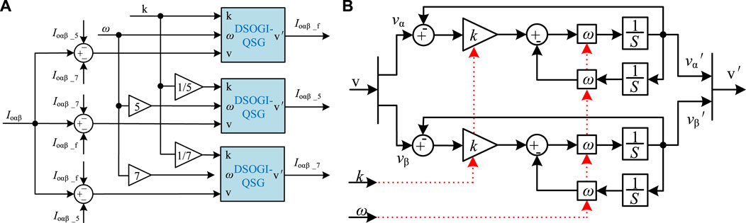
FIGURE 9. Signal separation module based on multiple second-order generalized integrators: (A) block diagram of the signal separation structure; (B) second-order generalized integrator structure.
Therefore, from Figure 9A and Eq. 19, the signal extraction transfer function can be derived as
In Eq. 20, ω is the fundamental angular frequency, and h is the signal frequency. The corresponding fundamental current components and 5th and 7th harmonic current components in the output grid-connected current can be extracted by setting the value of h to 1, 5, and 7 in the control system, respectively.
In the case of harmonic virtual impedance introduction, the voltage–current dual closed-loop equivalent model can be constructed, as shown in Figure 10A, which can be transformed to a single-loop form, as shown in Figure 10B, by moving the comparison and lead points. Thus, the system open-loop transfer function can be obtained as follows:
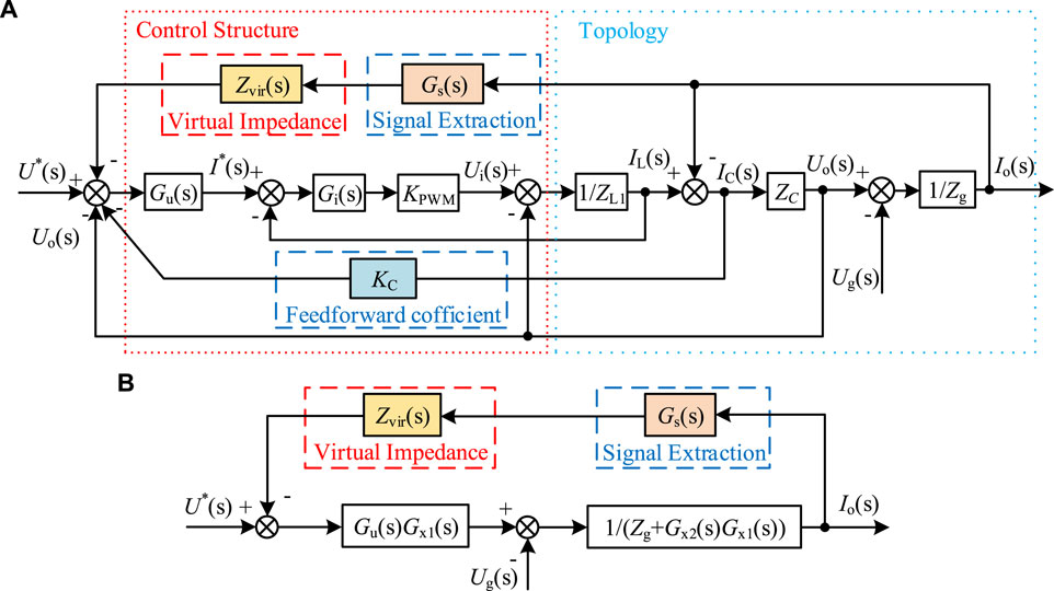
FIGURE 10. Voltage–current dual closed-loop equivalent model introduced by virtual impedance: (A) original equivalent model and (B) simplified equivalent model.
where Gx1(s) and Gx2(s), respectively, can be expressed using Eqs 22, 23:
The introduction of the harmonic virtual impedance should first ensure that the system stability is not destroyed. In this paper, the range of the harmonic virtual impedance value setting is determined by the root-locus change in the system open-loop transfer function, and finally, a suitable harmonic virtual impedance value is selected from the optional range to improve the grid-connected inverter output grid current quality.
4.2 Harmonic virtual impedance parameter design
The design of the harmonic virtual impedance value first needs to meet the system stability requirements, and it is known from the literature (Ni et al., 2013) that the virtual impedance can be designed as inductive or resistive, or it can be composed of both resistive and inductive impedance components. However, the fundamental virtual impedance is usually designed as inductive to ensure the overall inductive state of the three-phase voltage-source grid-connected inverter system and avoid the need to redesign the VSG control structure. Thus, the resistive component of the fundamental virtual impedance can be set to 0. The harmonic virtual impedance only needs to be designed as resistive to attenuate the harmonic current component of the grid voltage that flows into the grid through the line impedance. According to the open-loop transfer function of the system expressed in Eq. 21, the root locus of the parameters is drawn, and the root-locus curves of the fundamental virtual inductance Lv1, the 5th harmonic virtual resistance Rv5, and the 7th harmonic virtual resistance Rv7 are used as the changing parameters. The root-locus curves are compared using the criterion whether they cross the right half-plane of s under different parameter values. The selection range of each harmonic virtual impedance is determined by comparing whether the root-locus curve crosses the right half-plane of s for different parameter values.
Figure 11 shows the root-locus curve of the open-loop transfer function of the system when the fundamental virtual inductance Lv1, the 5th harmonic virtual resistance Rv5, and the 7th harmonic virtual resistance Rv7 are used as changing parameters. Figure 11A shows the root-locus curve of the fundamental virtual inductance Lv1 varying in the range of 0–2 mH, and the root-locus curve, as shown in Figure 11B, is obtained by enlarging the curve in the red dashed box of Figure 11A, and the straight line with arrows in the figure points to the trend of the root-locus change as Lv1 increases. It can be seen from the figure that when Lv1 varies in the range of 0–2 mH, the root-locus curve of the system is in the s-left half-plane, and there is no s-right half-plane pole, which means the system is stable. However, when Lv1 varies in the range of 0–3 mH, the root-locus curve, as shown in Figure 11C, is obtained, and it can be seen from Figure 11D, which is obtained by enlarging the selected part of the curve in Figure 11C, that when Lv1 varies in the range of 0–3 mH, the system has a right half-plane poles, and the system stability cannot be guaranteed at this time, so the Lv1 should be selected in the range of 0–2 mH.
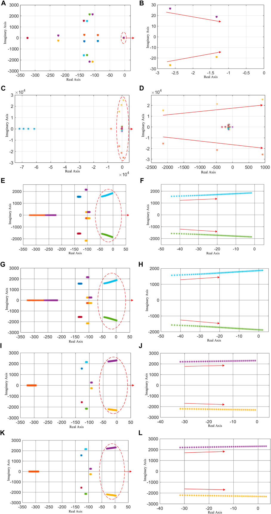
FIGURE 11. Root-locus curve with the virtual inductance Lv1, the 5th harmonic virtual resistance Rv5, and the 7th harmonic virtual resistance Rv7 as changing parameters, respectively: (A) root locus of Lv1 varying in the range of 0–2 mH; (B) local range of the root locus of Lv1 varying in the range of 0–2 mH; (C) root locus of Lv1 varying in the range of 0–3 mH; (D) local range of the root locus of Lv1 varying in the range of 0–3 mH; (E) root locus of Rv5 varying in the range of 0–50 Ω; (F) local range of the root locus of Rv5 varying in the range of 0–50 Ω; (G) root locus of Rv5 varying in the range of 0–55 Ω; (H) local range of the root locus of Rv5 varying in the range of 0–55 Ω; (I) root locus of Rv7 varying in the range of 0–35 Ω; (J) local range of the root locus of Rv7 varying in the range of 0–35 Ω; (K) root locus of Rv7 varying in the range of 0–40 Ω; and (L) local range of the root locus of Rv7 varying in the range of 0–40 Ω.
When the 5th harmonic virtual resistance Rv5 is taken as the parameter and set to vary in the range of 0–50 Ω, the root-locus curve, as shown in Figure 11E, is obtained, and the local root-locus curve shown in Figure 11F is obtained by enlarging the curve in the red dashed box in Figure 11E, and the straight line with arrow in the figure points to the root-locus change trend as Rv5 increases. From the figure, it can be seen that when Rv5 varies from 0 to 50 Ω, the system root-locus curves are in the s-left half-plane, and there is no s-right half-plane pole, which means that the system is stable. However, when Rv5 is varied in the range of 0–55 Ω, the root-locus curve is obtained, as shown in Figure 11G, and it can be seen from Figure 11H, which is obtained by enlarging the selected part of the curve in Figure 11G, that when Rv5 is varied in the range of 0–55 Ω, the system has the s right half-plane pole, and the system stability cannot be guaranteed at this time, so the Rv5 should be selected in the range of 0–50 Ω.
According to the root locus shown in Figures 11I, J, when Rv7 is varied in the range of 0–35 Ω, the system root-locus curves are all in the s-left half-plane, and there is no right plane pole, indicating that the system is stable. According to the root-locus curve shown in Figures 11K, L, when Rv7 varies in the range of 0–40 Ω, the system root-locus curve crosses the s-left half-plane, indicating that the system has right half-plane poles. Moreover, the system stability cannot be guaranteed at this time, so the value of the 7th harmonic virtual resistance Rv7 should be selected in the range of 0–35 Ω.
After using the root-locus stability criterion to determine the value range of each harmonic virtual impedance, the value of each harmonic virtual impedance is set under the premise of ensuring system stability, and the algebraic harmonic virtual impedance implementation method proposed in Wang et al. (2014)and Liu B. et al. (2019) is adopted to introduce the harmonic virtual impedance into the grid-connected inverter system to regulate the output grid-connected current. The signal separation module based on multiple second-order generalized integrators, as shown in Figure 9A, separates each frequency signal to obtain the fundamental current Ioαβ_f, the fifth harmonic current Ioαβ_5, and the seventh harmonic current Ioαβ_7. Then, the compensation voltage is obtained using the algebraic harmonic virtual impedance implementation method. The compensation voltage is expressed as follows:
where Rv1, Rv5, and Rv7 denote the virtual resistance introduced in the harmonic virtual impedance method. The fundamental virtual resistance Rv1 is set to 0, while the harmonic virtual resistances Rv5 and Rv7 are taken within the stability range analyzed by the root-locus method described previously. Lv1, Lv5, and Lv7 denote the virtual inductance introduced in the harmonic virtual impedance method after the root-locus method analysis. In this paper, the fundamental virtual inductance Lv1 is set to 2 mH, while the harmonic virtual inductances Lv5 and Lv7 are set to 0. After determining the value of each harmonic virtual impedance, the total voltage drop in the virtual impedance can be obtained by summing the compensation voltage components of each frequency, as shown in Eq. 27.
where Uzα and Uzβ are the calculated virtual impedance voltage drops at different axes in the two-phase stationary (αβ) coordinate system, which are introduced into the voltage outer loop of the voltage–current double closed-loop control in the form of negative feedforward, thus deducting them from the reference voltage. This virtual impedance introduction does not involve any differential operation and therefore does not introduce the problem of high-frequency noise amplification.
5 Simulation and experimental analysis
5.1 Simulation analysis
In order to verify the resonant spike suppression effect and the output grid-connected current quality improvement effect of the proposed control strategy, a three-phase voltage-source grid-connected inverter simulation model is established using Simulink, and the simulation parameters are designed according to Table 1.
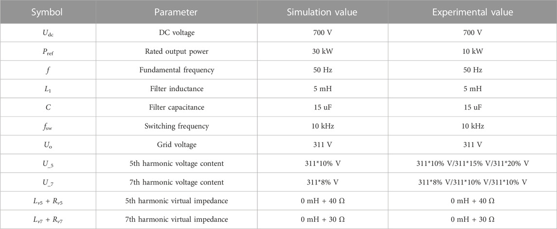
TABLE 1. Simulation and experimental parameters of the resonance suppression control strategy.
When the three-phase voltage-source grid-connected inverter is connected to the ideal grid and filtered by the LC filter, the output grid-connected current waveforms and THD obtained by FFT analysis without any resonance suppression control strategy are shown in Figures 12A, B, respectively. Figure 12A shows that that when the active damping control strategy is not introduced to control the three-phase voltage-source-type grid-connected inverter, the inherent resonance of the LCL filter formed by the LC filter and the line impedance in the topology structure will cause the grid-connected inverter system to resonate, resulting in the oscillation of the output grid-connected current. It can be seen from the figure that the output grid-connected current not only exhibits large amplitude fluctuations but also shows a non-sinusoidal defect in the waveform. Figure 12B also shows that the output grid-connected current THD has reached 90.84%, far exceeding the requirement of THD<5%. Therefore, it is necessary to adopt corresponding resonance suppression control strategies to suppress the resonance peaks, improve the system stability, and improve the quality of output grid-connected current to meet grid-connected standards.
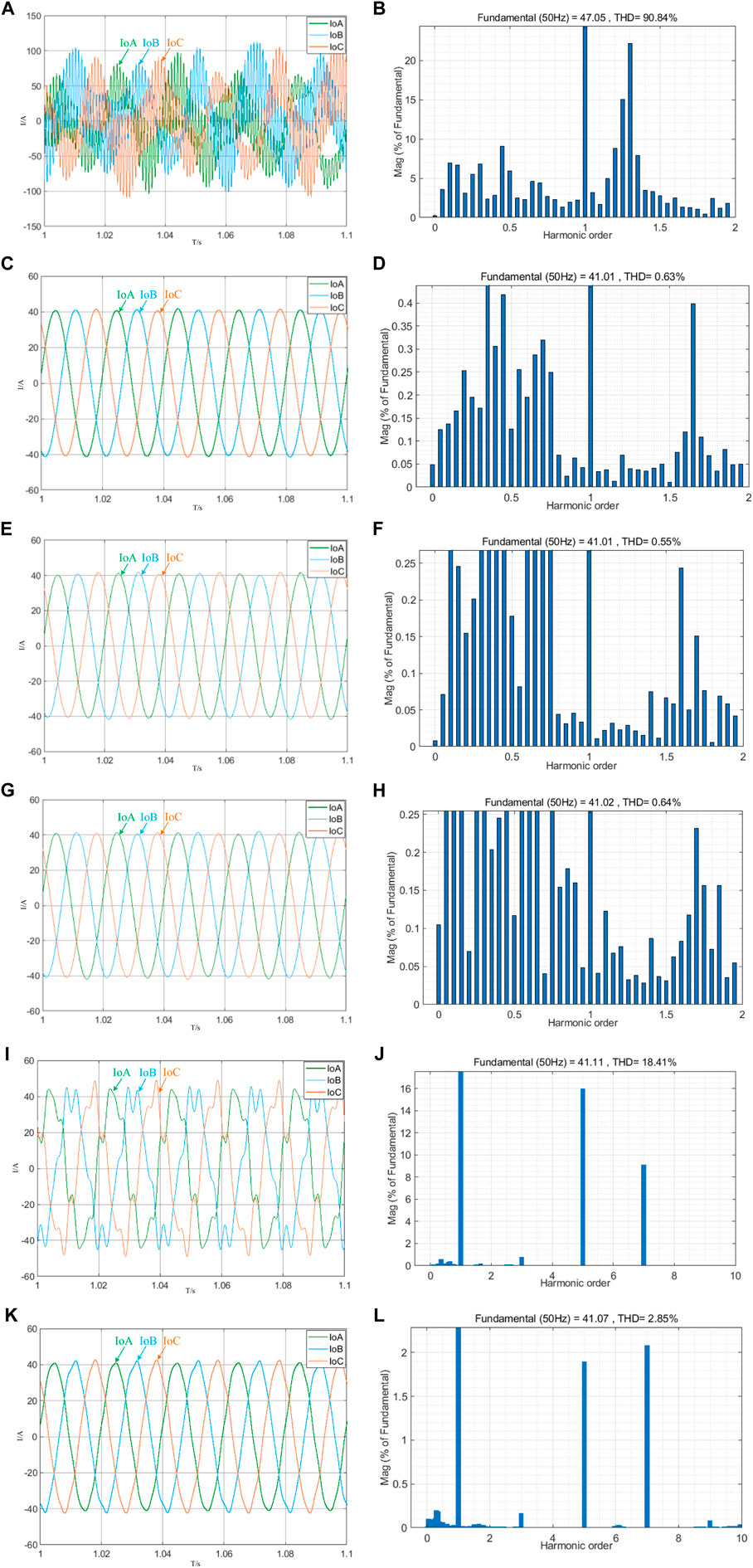
FIGURE 12. Output grid-connected current waveform and THD under various control strategies: (A) output grid-connected current waveform without the damping control strategy; (B) output grid-connected current THD without the damping control strategy; (C) output grid-connected current waveform when KC = 4; (D) output grid-connected current THD when KC = 4; (E) output grid-connected current waveform when KC = 8; (F) output grid-connected current THD when KC = 8; (G) output grid-connected current waveform when KC = 12; (H) output grid-connected current THD when KC = 12; (I) output grid-connected current waveform without harmonic virtual impedance; (J) output grid-connected current THD without harmonic virtual impedance; (K) output grid-connected current waveform with harmonic virtual impedance; and (L) output grid-connected current THD with harmonic virtual impedance.
The capacitor current feedforward active damping control strategy can effectively suppress the resonance of the inverter, but a suitable capacitor-current feedforward coefficient KC needs to be selected to achieve a good resonance suppression effect. In this regard, different values of KC are set in the simulation, and the stability of the output grid current waveform of the three-phase voltage-source grid-connected inverter and the THD of the output grid-connected current obtained by FFT analysis are observed under different values of KC to determine the best KC value to suppress the resonance of the inverter. The output grid-connected current waveforms and the corresponding THD after setting the capacitor-current feedforward coefficient KC to different values are shown in Figures 12C–I.
Comparing Figures 12A, C, E, G, it can be seen that the active damping control strategy of the capacitor-current feedforward can effectively suppress the resonance of the inverter, thereby greatly improving the stability of the system. By comparing Figures 12D, F, H, it can be seen that when the value of the capacitor-current feedforward coefficient KC is different, the resonance suppression effect is also different. When the capacitor-current feedforward coefficient KC is set to 8, the output grid-connected current THD is the smallest, which also proves that the value of the feedforward coefficient is not sufficiently large but should be selected under the condition of comprehensive consideration of the system bandwidth and phase margin requirements.
After the capacitor-current feedforward control strategy is used to successfully suppress the inverter resonance, the harmonic virtual impedance control strategy is combined to improve the quality of the output grid-connected current when the low-order harmonic content in the grid voltage is high. In this paper, the grid voltage contains the 5th harmonic whose amplitude is 10% of the fundamental amplitude and the 7th harmonic whose amplitude is 8% of the fundamental wave in the grid voltage for control.
When the grid voltage contains 10% of the 5th harmonic component and 8% of the 7th harmonic component, the grid voltage will introduce the harmonic current into the grid through the line impedance. At this time, if only the resonance suppression control strategy of the capacitive-current feedforward is adopted without the harmonic virtual impedance control strategy, the grid-connected current waveform is obtained, as shown in Figure 12I, and the output grid-connected current THD is obtained by FFT analysis as shown in Figure 12J. At this time, the output grid-connected current produces distortion and the THD reaches 18.41%, which cannot meet the grid-connected requirements.
The virtual impedance value is set according to Table 1, and the harmonic virtual impedance control strategy is introduced into the voltage and current double closed-loop control link. After the system is stable, the improved output grid-connected current waveform and the output grid-connected current THD obtained by FFT analysis is shown in Figures 12K, L.
Through the output grid-connected current waveform diagram after adopting the control strategy combining capacitive-current feedforward and harmonic virtual impedance, as shown in Figure 12K, it can be seen that the quality of the output grid-connected current has been greatly improved. At this time, the output grid-connected current THD is obtained as shown in Figure 12L. The THD value is 2.85%, which meets the network access standard of THD<5%. This shows that the harmonic virtual impedance control strategy can improve the quality of the output grid-connected current.
5.2 Experimental analysis
To verify the effectiveness of the proposed resonance suppression control strategy and harmonic virtual impedance control strategy, a three-phase two-level DC–AC converter module (YXPHM-TP210b-I) is used in this paper with a rated power of 10 kW as the research subject, which is shown in Figure 13. Experimental analysis is carried out by introducing the resonance suppression control strategy proposed in this paper and the grid-connected current quality improvement control strategy. The switch tube of the three-phase bridge arm of the inverter adopts the IGBT of the model FS100R12KT4G, the withstand voltage is 1,200 V, and the maximum reverse current is 100 A. The DC side uses a DC source (Chroma 62150 H-1000 s) to power the prototype. The voltage and current signals in the main circuit topology that need to be used in the control structure are collected through the ADC sampling module, the sampling signals are sent to the dSPACE controller, and the dSPACE controller is used to generate PWM signals to control the three-phase voltage-source type grid-connected inverter. The switching tube of the transformer prototype is turned off, the DAC conversion module is used to convert the output digital current signal into an analog signal, and the output grid-connected current signal waveform is observed through an oscilloscope (Tektronix MDO3034). This experiment will verify the rationality and effectiveness of the resonance suppression control strategy and the parameter design in the grid-connected current quality improvement control strategy by observing the output grid-connected current THD under the operating condition of the experimental prototype at an output power of 2 kW.
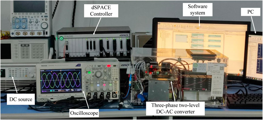
FIGURE 13. Three-phase two-level grid-connected inverter experimental device.
It can be seen from the simulation analysis that different values of the capacitor-current feedforward coefficient KC will have different resonance suppression effects. Therefore, research on resonance suppression experiments will verify this conclusion by setting different capacitor-current feedforward coefficients KC under ideal grid conditions. The output grid-connected current under different values of the capacitor current feedforward coefficient KC is shown in Figures 14A–C.
It can be seen from Figures 14A–C that after the introduction of the capacitive-current feedforward control strategy to suppress the resonance of the three-phase voltage-source grid-connected inverter, the inverter output grid-connected current waveform has a higher degree of sinusoidalization. The output grid-connected current THD shown in Figures 14A–C is 3.05%, 2.93%, and 3.12%, respectively, which meet the grid requirements. This shows that the resonance of grid-connected inverters can be effectively suppressed by designing a capacitive-current feedforward active damping control strategy with a reasonable capacitive-current feedforward coefficient. In addition, the THD under different feedforward coefficient values also shows that the system bandwidth and phase margin requirements should be fully considered when selecting the capacitor-current feedforward coefficient.
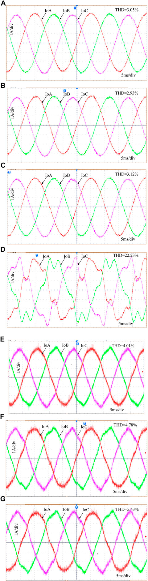
FIGURE 14. Output grid-connected current waveform under various control strategies: (A) capacitor-current feedforward coefficient KC = 4; (B) capacitor-current feedforward coefficient KC = 8; (C) capacitor-current feedforward coefficient KC = 12; (D) harmonic virtual impedance without the control strategy; (E),(F), and (G) harmonic virtual impedance with the control strategy.
After using the capacitive-current feedforward control strategy to solve the inverter system resonance problem under ideal grid conditions, it is necessary to verify the control strategy for output grid-connected current quality improvement in the case of high low-order harmonic content in the grid voltage through experiments. In this study, the feasibility of the proposed control strategy is verified by setting different contents of 5th harmonic voltage and 7th harmonic voltage to simulate the grid voltage distortion under weak grids. According to the experimental parameters in Table 1, the harmonic virtual impedance control strategy is designed and introduced into the control link of the three-phase voltage-source grid-connected inverter, and the grid-connected current is collected and output using an oscilloscope. The correctness and effectiveness of the grid-connected current quality improvement control strategy proposed in this paper can be determined by observing the output grid-connected current waveforms under the current quality improvement control strategy combining capacitor-current feedforward and harmonic virtual impedance. The output grid-connected current waveforms of the three-phase voltage-source grid-connected inverter after using multiple control strategies are shown in Figures 14D–G, respectively.
Figure 14D shows that in the case of high harmonic content in the grid voltage, if only the capacitive current feedforward control strategy is introduced without introducing an additional grid-connected current quality improvement control strategy, the output grid-connected current will be distorted when the voltage component is controlled. In the experiment, the output grid-connected current THD of the inverter reached 22.23%, which does not meet the grid-connected requirements. It is difficult for the system to maintain stability under this working condition. Under the same power grid conditions, by introducing the harmonic virtual impedance control strategy, the 5th harmonic virtual impedance is set to 40 Ω, the 7th harmonic virtual impedance is set to 30 Ω, and the total voltage drop of the harmonic virtual impedance is obtained using an algebraic form. After feeding it to the voltage and current double closed-loop control, the output grid-connected current waveforms, as shown in Figures 14E–G, are obtained for different harmonic contents, respectively. It can be seen from the figure that after using the harmonic virtual impedance control strategy, the THD obtained is 4.01%, 4.78%, and 5.43%, respectively, with different harmonic contents according to the harmonic content design in Table 1. Therefore, combining the simulation results, as shown in Figure 12, and the experimental results, as shown in Figure 14, it can be seen that the grid-connected current quality improvement control strategy based on harmonic virtual impedance proposed in this paper is able to improve the power quality of the system with a certain range of harmonic content.
6 Conclusion
In this paper, the control strategy for the inverter resonance and grid-connected current distortion of a three-phase voltage-source grid-connected inverter under a weak grid is studied. An active damping control scheme using capacitor-current feedforward is proposed to suppress the resonance, and the value of the feedforward coefficient KC is determined through the Bode diagram of the open-loop transfer function. In addition, a control strategy that combines capacitive-current feedforward and harmonic virtual impedance is proposed to improve the quality of the output grid-connected current. In the design process, the root-locus method is used to determine the selection range of the harmonic virtual impedance to maintain system stability. Finally, by observing the output grid-connected current waveform and THD through experiments, the feasibility and effectiveness of the control strategy for resonance suppression and grid-connected current quality improvement are verified.
Data availability statement
The original contributions presented in the study are included in the article/Supplementary Material; further inquiries can be directed to the corresponding author.
Author contributions
YL is in charge of method calculation, paper writing, and experiment. ZhiZ is in charge of the experimental setup and proofreading of the manuscript. CZ is in charge of the experimental setup and literature review. ZhaZ is in charge of the experimental guidance. All authors contributed to the article and approved the submitted version.
Funding
This research was funded by the Guangdong Basic and Applied Basic Research Foundation (No. 2022A1515140009).
Conflict of interest
The authors declare that the research was conducted in the absence of any commercial or financial relationships that could be construed as a potential conflict of interest.
Publisher’s note
All claims expressed in this article are solely those of the authors and do not necessarily represent those of their affiliated organizations, or those of the publisher, the editors, and the reviewers. Any product that may be evaluated in this article, or claim that may be made by its manufacturer, is not guaranteed or endorsed by the publisher.
Supplementary material
The Supplementary Material for this article can be found online at: https://www.frontiersin.org/articles/10.3389/fenrg.2023.1231992/full#supplementary-material
References
Aapro, A., Messo, T., and Roinila, T. (2017). Effect of active damping on output impedance of three-phase grid-connected converter. IEEE Trans. Industrial Electron. 64 (9), 7532–7541. doi:10.1109/tie.2017.2696494
Dang, C., Tong, X., and Song, W. (2021). “Capacitive current feedforward control strategy for a three-phase LCL-filter-based T-type grid-connected converter with the fuzzy-PR,” in 2021 33rd Chinese Control and Decision Conference (CCDC), Kunming, China, 22-24 May 2021, 7589–7594.
Dursun, M., and Döşoğlu, M. K. (2018). “LCL filter design for grid connected three-phase inverter,” in 2018 2nd International Symposium on Multidisciplinary Studies and Innovative Technologies (ISMSIT), Ankara, Turkey, 19-21 October 2018, 1–4.
Fang, J., Li, H., Tang, Y., and Blaabjerg, F. (2018). On the inertia of future more-electronics power systems. IEEE J. Emerg. Sel. Top. Power Electron. 7 (4), 2130–2146. doi:10.1109/jestpe.2018.2877766
Guan, Y., Wang, Y., and Xie, Y. (2018). The dual-current control strategy of grid-connected inverter with LCL filter. IEEE Transac-tions Power Electron. 34 (6), 5940–5952. doi:10.1109/tpel.2018.2869625
Guo, B., Su, M., and Sun, Y. (2019). A robust second-order sliding mode control for single-phase photovoltaic grid-connected voltage source inverter. IEEE Access 7, 53202–53212. doi:10.1109/access.2019.2912033
Han, Y., Yang, M., Li, H., Yang, P., Xu, L., and Coelho, E. A. A. (2019). Modeling and stability analysis of $LCL$ -type grid-connected inverters: a comprehensive overview. IEEE Access 7, 114975–115001. doi:10.1109/access.2019.2935806
Hu, Y., Shao, Y., and Yang, R. (2019b). A configurable virtual impedance method for grid-connected virtual synchronous generator to improve the quality of output current. IEEE J. Emerg. Sel. Top. Power Electron. 8 (3), 2404–2419. doi:10.1109/jestpe.2019.2918386
Hu, Y., Shao, Y., Yang, R., and Chen, G. (2019a). “Current harmonic suppression for grid-connected VSG based on virtual harmonic impedance,” in 2019 10th International Conference on Power Electronics and ECCE Asia (ICPE 2019 - ECCE Asia), Busan, Korea (South), 27-30 May 2019, 2022–2026.
IEEE (1997). IEEE guide for planning DC links terminating at AC locations having low short-circuit capacities. IEEE Std 1204-1997 1997, 1–216. doi:10.1109/IEEESTD.1997.85949
IEEE (2003). IEEE standard for interconnecting distributed resources with electric power systems. IEEE Std 1547-2003 2003, 1–28. doi:10.1109/IEEESTD.2003.94285
Jin, W., Li, Y., Sun, G., Chen, X., and Gao, Y. (2018). Stability analysis method for three-phase multi-functional grid-connected inverters with unbal-anced local loads considering the active imbalance compensation. IEEE access 6, 54865–54875. doi:10.1109/access.2018.2871160
Karbasforooshan, M. -S., and Monfared, M. (2022). Adaptive self-tuned current controller design for an LCL-filtered LC-tuned single-phase shunt hybrid active power filter. IEEE Trans. Power Deliv. 37 (4), 2747–2756. doi:10.1109/tpwrd.2021.3115661
Knenicky, M., Prochazka, R., Hlavacek, J., and Sefl, O. (2021). Impact of high-frequency voltage distortion emitted by large pho-tovoltaic power plant on medium voltage cable systems. IEEE Trans. Power Deliv. 36 (3), 1882–1891. doi:10.1109/tpwrd.2020.3016952
Koiwa, K., Inoo, K., Zanma, T., and Liu, K. -Z. (2022). Virtual voltage control of VSG for overcurrent suppression under symmetrical and asymmetrical voltage dips. IEEE Trans. Industrial Electron. 69 (11), 11177–11186. doi:10.1109/tie.2021.3125654
Lai, N. B., and Kim, K. H. (2017). Robust control scheme for three-phase grid-connected inverters with <italic>LCL</italic>-Filter under unbalanced and distorted grid conditions. IEEE Trans. Energy Convers. 33 (2), 506–515. doi:10.1109/tec.2017.2757042
Li, F., Zhang, X., Zhu, H., Li, H., and Yu, C. (2015). An LCL-LC Filter for Grid-Connected Converter: topology, Parameter, and Analysis. IEEE Trans. Power Electron. 30 (9), 5067–5077. doi:10.1109/tpel.2014.2367135
Li, M., Zhang, X., Guo, Z., Wang, J., Wang, Y., Li, F., et al. (2020). The control strategy for the grid-connected inverter through impedance reshaping in q-axis and its stability analysis under a weak grid. IEEE J. Emerg. Sel. Top. Power Electron. 9 (3), 3229–3242. doi:10.1109/jestpe.2020.3024863
Li, S., and Lin, H. (2021). A capacitor-current-feedback positive active damping control strategy for LCL-type grid-connected in-verter to achieve high robustness. IEEE Trans. Power Electron. 37 (6), 6462–6474. doi:10.1109/tpel.2021.3137845
Lin, Z., Ruan, X., Wu, L., Zhang, H., and Li, W. (2020). Multi resonant component-based grid-voltage-weighted feedforward scheme for grid-connected inverter to suppress the injected grid current harmonics under weak grid. IEEE Trans. Power Electron. 35 (9), 9784–9793. doi:10.1109/tpel.2020.2970514
Liu, B., Liu, Z., and Liu, J. (2019b). An adaptive virtual impedance control scheme based on small-AC-signal injection for unbalanced and harmonic power sharing in islanded microgrids. IEEE Trans. Power Electron. 34 (12), 12333–12355. doi:10.1109/tpel.2019.2905588
Liu, T., Liu, J., Liu, Z., and Liu, Z. (2019a). A study of virtual resistor-based active damping alternatives for LCL resonance in grid-connected voltage source inverters. IEEE Trans. Power Electron. 35 (1), 247–262. doi:10.1109/tpel.2019.2911163
Lou, G., Yang, Q., Gu, W., Quan, X., Guerrero, J. M., and Li, S. (2021). Analysis and design of hybrid harmonic suppression scheme for VSG considering nonlinear loads and distorted grid. IEEE Trans. Energy Convers. 36 (4), 3096–3107. doi:10.1109/tec.2021.3063607
Ma, W., Guan, Y., Zhang, B., and Wu, L. (2021). Active disturbance rejection control based single current feedback resonance damping strategy for LCL-type grid-connected inverter. IEEE Trans. Energy Convers. 36 (1), 48–62. doi:10.1109/tec.2020.3006151
Mohammed, N., Ravanji, M. H., Zhou, W., and Bahrani, B. (2023). Online grid impedance estimation-based adaptive control of virtual synchronous generators considering strong and weak grid conditions. IEEE Trans. Sustain. Energy 14 (1), 673–687. doi:10.1109/tste.2022.3223976
Mondal, S., Gayen, P. K., and Gupta, K. (2018). “Study on impact of LC-filter parameters under variable loading conditions of three-phase voltage source inverter,” in 2018 IEEE Electron Devices Kolkata Conference (EDKCON), Kolkata, India, 24-25 November 2018, 132–136.
Ni, R., Li, Y. W., and Zhang, Y. (2013). Virtual impedance-based selective harmonic compensation (VI-SHC) PWM for current source rectifiers. IEEE Trans. power Electron. 29 (7), 3346–3356. doi:10.1109/tpel.2013.2280217
Stojić, Đ. M., and Šekara, T. B. (2022). Digital resonant current controller for LCL-filtered inverter based on modified current sampling and delay modeling. IEEE J. Emerg. Sel. Top. Power Electron. 10 (6), 7109–7119. doi:10.1109/jestpe.2022.3190285
Tang, W., Ma, K., and Song, Y. (2021). Critical damping ratio to ensure design efficiency and stability of LCL filters. IEEE Trans. Power Electron. 36 (1), 315–325. doi:10.1109/tpel.2020.3000897
Vijay, A. S., and Doolla, S. (2021). Performance of droop control techniques under nonlinear loading conditions: uniform and nonuniform configurations. IEEE Syst. J. 15 (2), 2245–2256. doi:10.1109/jsyst.2020.2996252
Wang, X., Li, Y. W., and Blaabjerg, F. (2014). Virtual-impedance-based control for voltage-source and current-source converters. IEEE Trans. Power Electron. 30 (12), 7019–7037. doi:10.1109/tpel.2014.2382565
Wang, X., Ruan, X., and Liu, S. (2010). Full feedforward of grid voltage for grid-connected inverter with LCL filter to suppress current distortion due to grid voltage harmonics. IEEE Trans. Power Electron. 25 (12), 3119–3127. doi:10.1109/tpel.2010.2077312
Zeng, C., Wang, H., and Li, S. (2021). Grid-voltage-feedback active damping with lead compensation for LCL-type inverter connected to weak grid. IEEE Access 9, 106813–106823. doi:10.1109/access.2021.3101501
Zhang, H., Ruan, X., and Lin, Z. (2020). Capacitor voltage full feedback scheme for LCL-type grid-connected inverter to suppress current distortion due to grid voltage harmonics. IEEE Trans. Power Electron. 36 (3), 2996–3006. doi:10.1109/tpel.2020.3014338
Zhang, X., Chen, P., and Yu, C. (2016). Study of a current control strategy based on multisampling for high-power grid-connected inverters with an LCL filter. IEEE Trans. Power Electron. 32 (7), 5023–5034. doi:10.1109/tpel.2016.2606461
Zhao, E., Han, Y., Lin, X., Liu, E., Yang, P., and Zalhaf, A. S. (2022). Harmonic characteristics and control strategies of grid-connected photovoltaic inverters under weak grid conditions. Int. J. Electr. Power & Energy Syst. 142, 108280. doi:10.1016/j.ijepes.2022.108280
Zhong, P., Sun, J., Tian, Z., Huang, M., Yu, P., and Zha, X. (2021). An improved impedance measurement method for grid-connected inverter systems considering the background harmonics and frequency deviation. IEEE J. Emerg. Sel. Top. Power Electron. 9 (4), 4236–4247. doi:10.1109/jestpe.2020.2989436
Zhou, S., Zou, X., Zhu, D., Tong, L., Zhao, Y., Kang, Y., et al. (2017). An improved design of current controller for <italic>LCL</italic>-Type grid-connected converter to reduce negative effect of PLL in weak grid. IEEE J. Emerg. Sel. Top. Power Electron. 6 (2), 648–663. doi:10.1109/jestpe.2017.2780918
Keywords: three-phase voltage-source grid-connected inverter, inverter resonance suppression, harmonic virtual impedance, grid-connected current quality, root locus
Citation: Zhang Z, Li Y, Zhong C and Zhang Z (2023) Resonance suppression and quality improvement control strategy for a three-phase grid-connected voltage-source inverter under weak grid conditions. Front. Energy Res. 11:1231992. doi: 10.3389/fenrg.2023.1231992
Received: 31 May 2023; Accepted: 03 August 2023;
Published: 17 August 2023.
Edited by:
Razzaqul Ahshan, Sultan Qaboos University, OmanCopyright © 2023 Zhang, Li, Zhong and Zhang. This is an open-access article distributed under the terms of the Creative Commons Attribution License (CC BY). The use, distribution or reproduction in other forums is permitted, provided the original author(s) and the copyright owner(s) are credited and that the original publication in this journal is cited, in accordance with accepted academic practice. No use, distribution or reproduction is permitted which does not comply with these terms.
*Correspondence: Zhi Zhang, emhhbmd6QGRndXQuZWR1LmNu