 Zhicheng Li1Jinyu Chen1Weijun Zhang1
 Dawei Chen1*Shuling Zhang1Tongtong Gao1Wei Zhang2
 Zhenxiong Wang2
- 1State Grid Fujian Electric Power Research Institute, Fuzhou, China
- 2School of Electrical Engineering Xi’an Jiaotong University, Xi’an, China
With the rapid increase in the use of renewable energy sources, the strength of the power grid is reduced, which may lead to many weak distribution networks. The inertia of the weak distribution network decreases significantly, which leads to poor voltage quality. It means that the voltage and frequency are distorted and deviated. Battery storage can balance the frequent power disturbance and improve the frequency quality. However, it usually requires a central controller to dispatch the power in the current-controlled mode or respond natively with a fixed linear curve in voltage-controlled mode. The performance is poor when the power demand is in a wide range, which further deteriorates the frequency quality. To solve this problem, this paper proposes an adaptive frequency deviation improvement method for energy storage in the voltage-controlled mode. This method can change the power output characteristics of the storage inverter according to the magnitude and trend of power demand, where both frequency deviation and changing rate are used to shape the output power curve. A transfer function model for a voltage-controlled storage inverter is set up for theoretical analysis. Then, with the model, an adaptive frequency deviation improvement method is proposed with a fast response to power demand in a wide range. Finally, the results verify the effectiveness of the proposed method for frequency quality improvement with a high penetration level of stochastic photovoltaic power.
1 Introduction
Compared with traditional energy sources, new energy sources are environment friendly, clean, and sustainable (Bevrani, Ghosh et al., 2010). Renewable energy sources are gradually replacing traditional fossil fuels and may occupy a dominant position in the future energy structure, which is also the vision of many countries (Ackermann, Prevost et al., 2017). However, the extensive integration of random and volatile renewable energy sources has resulted in a significant decline in the power quality within the power grid (Yang, Dong et al., 2019). As renewable energy sources make up a larger share of the power system, the power grid becomes more like a weak grid in its characteristics (Xie, Huang et al., 2014). This leads to the problem in power balance after the decrease in the equivalent moment of inertia (Meng, Zafar et al., 2020). Therefore, the system’s frequency regulation capacity significantly decreases, leading to frequency fluctuation and deviation (Chowdhury and Asaduz-Zaman, 2014).
The frequency regulation of the microgrid is mainly achieved by controlling the output power of the micropower supply, while the frequency adjustment of the distribution network is mainly achieved by controlling the output power of synchronous generators (SGs). With the high penetration of renewable energy, the SGs cannot support the voltage and frequency quality with similar good performance as before. Therefore, the frequency deviation may cause a more serious influence and deteriorate the frequency quality of the power grid, including SGs, grid-connected equipment, and customers (Dong, Yang et al., 2022) (Amaripadath, Roche et al., 2017). For example, the speed of the motor is related to the frequency, where the frequency deviation will make the motor speed change. In addition, the unstable frequency may lead to the failure of some electronic equipment. Furthermore, the SGs and power grid may suffer serious adverse effects from frequency deviation, such as causing the steam turbine blade to resonate, break, and grid disintegrate. Therefore, it is important to solve the frequency fluctuation and deviation problems that originate with highly penetrated renewable energy.
In traditional power systems, SGs can suppress load fluctuations and maintain frequency stability through adjustable input power from the prime mover and rotor inertia (Ye, Pei et al., 2016). However, with the large-scale integration of randomly fluctuating renewable energy sources like solar energy, the traditional frequency regulation units require frequently changing the operational state, which may surpass the capability of the rotating machine in response speed. It means that the response speed of the primary frequency regulation of the SG is too slow due to physical limitations. This problem may accelerate the aging and wear of the SG (Liu et al., 2022a). Therefore, the transient power is unbalanced due to the slow response of the SG, which makes the frequency quality difficult to meet the requirements in the early stage after the grid is disturbed by renewables and large loads (Chen, Yue et al., 2021).
The storage converter can quickly process power in bio-directions, which can be used to solve the problem brought by random fluctuation of the solar energy (Mathews and Rajeev, 2021). Recently, the storage inverter is applied in the distribution network to balance power flow, adjust power quality, and address the power outage (Swierczynski, Stroe et al., 2013). Moreover, the energy storage can work in the droop mode, where the output power changes with the varied frequency (Lasseter, Chen et al., 2020). This mode can help solve the frequency quality problems, including reducing the rate of change of frequency (RoCoF) and suppressing frequency deviation. Normally, the energy storage power is controlled through a specific droop curve with a fixed reference, drooping rate, and dead band (Wang Y. et al., 2019a). Current research shows that this control method can effectively help with the deterioration of the frequency quality when the disturbance behaves only like frequency deviation in a fixed range. However, it cannot deal with more complex problems, including 1) the frequency deviation in a wide range and 2) the different frequency-changing trends. The problems arise from the fast revolution of future distribution networks that demand high-quality electricity despite increased violent fluctuations from both the source and load sides. Therefore, the control method is required for further improvement in these aspects.
The control method of energy storage inverters is significant for the stable operation of the power grid. At present, energy storage inverters mostly utilize a current-controlled strategy (Pattabiraman, Lasseter et al., 2018). This method relies on the voltage phase obtained from the phase-locked loop to guide power tracking (Liu et al., 2022b). The power reference is usually given by a central controller through communication lines. However, the current-controlled method requires high computing and communication speed for the central controller. When the frequency quality deteriorates and the grid voltage fluctuates, the current-controlled method faces challenges in response speed and grid voltage support (Fu, Sun et al., 2021). Therefore, improving frequency quality using a current-controlled energy storage inverter is inherently flawed in weak distribution networks (Wang, Yi et al., 2021).
To deal with these problems of current-controlled storage inverters, the voltage-controlled method is preferred for supporting the voltage and frequency of the power grid (Xiong, Liu et al., 2021). Voltage-controlled inverters can provide support during dynamic and steady-state frequency fluctuations in the power system (Ackermann, Prevost et al., 2017). The power–frequency droop control can be adopted in the energy storage inverter with the voltage-controlled method. When the power is unbalanced between the source and the load, the frequency deviates and the inverter consumes or generates power to support the power balance (Shan, Yang et al., 2021) However, droop control has limitations in improving the dynamic frequency quality, and adding virtual inertia in the control loop can reduce the changing rate of the frequency after disturbance, thereby improving the frequency quality (Arco and Suul, 2014). This is also called the virtual synchronous generator control method (Zhao, Wang et al., 2023). These voltage-controlled methods typically operate with fixed characteristics (Kerdphol, Rahman et al., 2019). However, in future distribution networks with high penetration rates of renewable energy sources and large load-demand variation, the demand for high power quality remains (Wang, Yi et al., 2022). Therefore, the magnitude of power change may be large, and the changing rate increases, making it difficult to suppress frequency quality deterioration with traditional methods. A new method is required to improve frequency quality.
To enhance the frequency quality and solve the aforementioned problems, this paper proposes an adaptive frequency deviation improvement method for energy storage in the voltage-controlled mode. The method comprises four power compensation strategies that can adaptively regulate the output power based on the trend of the inverter output reference frequency deviation and changing rate. With this mode, the storage output power can be adjusted more quickly, which improves the bus frequency quality during the early stages of disturbance, and both the bus frequency deviation and changing rate decline.
2 Transfer function model for the voltage-controlled storage inverter
2.1 Voltage-controlled storage inverter
The topology of the voltage-controlled energy storage inverter is shown in Figure 1, which comprises a pre-stage DC–DC converter and a post-stage DC–AC inverter. The topology of the storage inverter used in this paper is a two-stage configuration. It should be noted that the conclusions drawn from this study can be expanded to other types of topologies as well.
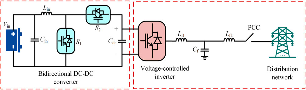
FIGURE 1. Topology of the voltage-controlled storage inverter.
The non-isolated buck–boost DC–DC converter can operate in both the boost mode and buck mode. When the power supplied by the energy storage cannot meet the load demand, the capacitor voltage of the DC bus is reduced and it operates in the boost mode. When the power of the energy storage is greater than the load demand, the capacitor voltage of the DC bus increases and operates in the buck mode. The control diagram of the pre-stage DC–DC conversion circuit is shown in Figure 2. Since this article focuses on the improvement of inverters to enhance grid-connected performance, the pre-stage DC–DC conversion circuit will not be introduced in detail. When analyzing the principle of the post-stage DC–AC circuit, the bus voltage of the DC capacitor is considered constant.
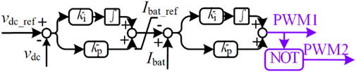
FIGURE 2. Control block diagram of the bidirectional DC/DC converter.
The control block diagram of the inverter circuit for post-stage DC–AC voltage control is shown in Figure 3A, B. Unlike conventional current-controlled inverters, the voltage-controlled method does not require the phase-locked loop to obtain the voltage phase information of the power grid, so the control accuracy will not be affected by the accuracy of the phase-locked loop. The voltage-controlled inverter calculates the active power Pe and reactive power Qe output on the side of the energy storage inverter by sampling the voltage uabc of the filter capacitor Cf and the current iabc flowing through the filter inductor Lf2. Then, it imitates the droop characteristics of the traditional synchronous machine with a reactive power–voltage droop (Q–U droop) and active power–frequency droop (P–f droop). After obtaining the amplitude E and phase θ of the inverter output reference voltage, it finally obtains the PWM wave via the voltage and current dual closed-loop control.
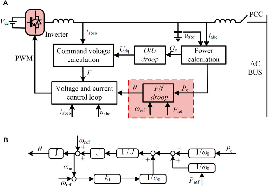
FIGURE 3. Control block diagram of the voltage-controlled inverter: (A) voltage-controlled inverter diagram; (B) P-f droop control diagram.
2.2 Derivation of the transfer function model
For the SG, with inductive impendence, the frequency is related to active power. Similarly, the active and reactive powers are decoupled with inductive line impedance. To imitate inertia in the SG, a mechanical model needs to be added to the P–f loop of the inverter, which associates power demand with the frequency changing rate. Moreover, the input power of the SG is determined by the frequency governor, which connects active power with frequency deviation. The detailed model derivation in this section can be also found in the study conducted by Wang Z. et al. (2019b). The P–f loop applied in this paper has a mechanical model and frequency governor, which are shown in Eqs 1, 2, respectively:
where J is the virtual inertia; ωm is the frequency of output voltage in the capacitor Cf; pin is the input power of energy storage; pe is the output power of the inverter; D is the damping coefficient; ωg is the frequency of the power grid; kd is the droop coefficient; Pref is the reference power of the inverter; and ωref is the reference frequency. ωm and ωg are approximately equal usually. Therefore, to simplify the analysis, the damping coefficient D can be ignored. ωm and ωref are approximately equal usually as the inverter operates near the nominal frequency. Hence, Eq. 3 is derived. The voltage-controlled diagram is shown in Figure 3B.
The small-signal model of Eq. 3 is derived around the operating point. Then, Eq. 4 is obtained. It shows the relationship between the frequency of the output voltage and output power. The relationship is that the frequency change is influenced by virtual inertia J and droop coefficient kd.
In the voltage-controlled mode, the output voltage of capacitor Cf is controlled to track the reference voltage as the terminal voltage. As described previously, the impedance between the terminal of the inverter and PCC is regarded as inductive. Therefore, the relationship between the active power and the phase difference is shown in Eq. 5, where Um is the amplitude of the output voltage in capacitor Cf, Ul is the amplitude of the ac bus voltage, δ is the phase difference between Um and Ul, XL is the equivalent inductance of the inverter in the grid side, and km is the power coefficient. The coefficient km is the ratio of the output power to the phase difference. Since the phase difference ∆δ is small, the change in output power ∆pe with ∆δ can be approximated by the following equation:
As phase difference is the integral of frequency difference, Eq. 6 can be derived from Eq. 5, where ωl is the frequency of the ac bus.
Eq. 7 should be satisfied, where ∆pload is the small-signal fluctuation between the source and load power.
In this model, the power grid is considered a strong grid, and hence, it is modeled by an ideal voltage source connected in series with line impedance. Therefore, the power coefficient km is also used in grid power transfer, and the symbol is replaced by kg, which is shown in Eq. 8, where Ug is the amplitude of the power grid voltage and Xg is the equivalent inductance of the grid.
Eqs 4–8 are combined, and the ideal transfer functions for the voltage-controlled energy storage connected to the power grid are derived as Eqs 9–11, where Gph_l, Gpe, and Gωm indicate the influence of power change to the phase change of ac bus voltage, output power change of the inverter, and output frequency ωm change, respectively. Therefore, the dynamic response of the inverter and ac bus after load power change with an ideal voltage source can be analyzed theoretically. This is the model in the strong grid. Wang Z. et al. (2019b) showed that the frequency change is not large with low impedance in the grid-connected mode.
As the derived transfer functions before, the frequency dynamics of the voltage-controlled inverter in the transient state connected to the ideal grid can be analyzed. When renewable energy sources are highly penetrated in the power grid, the model of the ideal voltage source cannot simulate the power unbalance from the lack of backup power. Therefore, the response time delay of the SG needs to be considered to analyze large-scale renewable energy connected to weak distribution networks, which is the aim of the following section.
3 Transfer function model of weak distribution networks
3.1 Model derivation
As mentioned previously, the power grid is regarded as an ideal voltage source, which cannot accurately reflect the characteristics of weak distribution networks. In weak distribution networks, the capability of power transmission from the power grid is limited, resulting in slower power response speed and larger equivalent impedance, both of which must be accounted for in network modeling. Since the renewable capacity is equal to the SG capacity or even larger than the SG capacity, the non-ideal conditions, including response delay and line impendence of the SG, are added to the model. Hence, the weak distribution network comprises a weak power grid, large-capacity PV inverters, and ac loads. Then, the storage inverter is integrated to improve the frequency quality. The whole topology of the weak distribution network is shown in Figure 4.
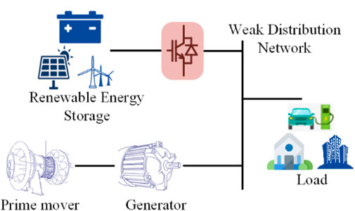
FIGURE 4. Structure of the weak distribution network.
For the SG, when the ac bus frequency deviates, the input power point is adjusted with the frequency governor. Then, the real input power is adjusted to follow the point. However, limited by the physical mechanism of change of the prime mover’s power, the time constant of delay is large. In weak distribution network, the influence of this delay is amplified with reduced inertia. To imitate this characteristic, a time delay Tpr is added to the voltage-controlled inverter. The transfer function model from the previous section needs to be updated. To update the model, Eq. 2 can be rewritten as Eq. 12, where Pin_ref is the reference input power of energy storage.
Therefore, Eq. 3 can be rewritten as Eq. 13, and the incremental formula of Eq. 13 is shown as Eq. 14.
Since the power grid has been assumed to be a voltage-controlled inverter before, the power coefficient kg in Eq. 9 is not applicable now, and considering it has many renewable energy sources, Eq. 9 will become Eq. 15, where i is the total number of energy sources, τine_n = Jωsm/kd_n and kimp_n = km_n/kd_n.
If the source is the SG, the relationship parameters formed with Tpr is shown as follows:
Therefore, the weak distribution network formula of Eqs 9–11 will be derived as Eqs 17–19, where Gpe_n is the nth energy source output power change when the power changes and Gωm_n is the nth energy source output frequency change.
Differentiating Eq. 17, the transfer function of the frequency change with regard to the power change is shown as follows:
3.2 Grid frequency deviation in weak distribution networks
Applying the nonideal model to the two energy source parallels in the power grid, as shown in Figure 4, has an SG and a renewable energy source. As mentioned previously, the time delay of the prime mover and weak grid with larger impendence and smaller inertia significantly deteriorates the frequency quality of the power grid. To reflect the characteristics of the weak distribution network with high-penetration renewable energy, Figures 5–7 show ac bus frequency with a different line impendence Xg, time delay Tpr, and inertia J of the SG source after the power change introduced by the stochastic PV power or load power. When the load changes, the frequency of the power grid decreases further, as shown in Figure 5.
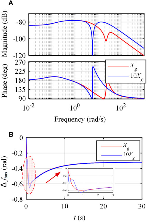
FIGURE 5. Power change influence on the ac bus frequency with a different line impendence Xg: (A) Bode diagram; (B) frequency response when load increases.
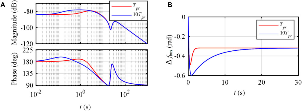
FIGURE 6. Power change influence on the ac bus frequency with a different time delay Tpr: (A) Bode diagram; (B) frequency response when load increases
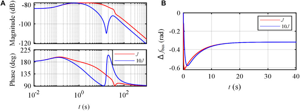
FIGURE 7. Power change influence on the ac bus frequency with a different virtual inertia J: (A) Bode diagram; (B) frequency response when load increases.
The SG regulates the frequency by changing the input power from the prime mover, which means it has a larger time delay than the storage inverter. Then, the frequency changes more quickly with a larger deviation after the power change. As shown in Figure 6, when the equivalent Tpr increases, the frequency changing rate increases, which means it takes longer to reach the new steady-state and larger RoCoF. Therefore, improving the storage inverter’s performance of output power in the weak distribution network is important to enhance frequency quality.
As shown in Figure 7, the inertia J also influences the dynamic ac bus frequency response, and a bigger equivalent J can reduce the RoCoF and nadir of frequency. Therefore, virtual inertia can help improve the frequency quality in the dynamic state.
4 Adaptive power demand control to support frequency
As mentioned previously, with high renewable energy penetration, the equivalent inertia decreases and impendence increases, which makes the power grid frequency quality significantly deteriorate after a large disturbance. In addition, as SG capacity relatively decreases, the line impedance increases, the SG cannot quickly provide enough backup power, and the capability for frequency regulation is not enough. To solve these problems, this paper proposes an adaptive frequency deviation improvement method for storage inverters in the voltage-controlled mode. This method can change the power output characteristics of the storage inverter according to the magnitude and trend of power demand, where both frequency deviation and changing rate are used to shape the output power curve. This method is divided into four kinds of power compensation methods after considering the magnitude and trend of frequency deviation.
Normally, the traditional droop control is a common method to change output power according to the frequency deviation. In addition, the additional power is transferred when the frequency reaches an undesired large value. These two kinds of power control methods will improve the frequency quality according to the frequency deviation. Furthermore, the frequency changing trend, which is also called the rate of change of frequency, is used to change the output power. It also includes two types of additional power compensation methods. One is linearly related to the RoCoF, and the other is step compensation if the RoCoF reaches a large value. These four power compensation methods use the inverter output reference frequency deviation (∆fm) and its changing rate (rocof (fm)) to improve the frequency quality.
4.1 Droop compensation
The energy storage inverter in the voltage-controlled mode with fixed inertia J can support bus voltage frequency, while the frequency and its changing rate are not large. Therefore, the energy storage can support bus frequency by the nature droop characteristic when the grid normally works near the rated point. The power curve of the nature droop compensation is shown in Figure 8A, where kfcom1 is the droop coefficient, Pcom1 is the first power compensation for frequency deviation, fm is the nominal frequency, and P0 is the nominal output power.
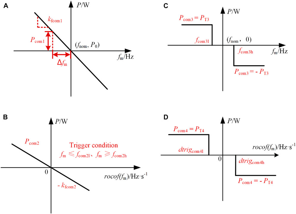
FIGURE 8. Diagram of shaping the output power curve: (A) droop compensation; (B) inertia compensation; (C) fast power compensation; and (D) fast inertia compensation.
4.2 Inertia compensation
The kfcom1 and J of droop compensation are normally fixed in traditional frequency support. This method cannot deal with the situation in which the frequency varies in a wide range or changes very quickly. Therefore, the extra output power is required when the rocof (fm) is large in addition to the normal inertia compensation. To ensure that the rocof (fm) can be restricted, extra output power is required, and this power curve is shown in Figure 8B. As shown in Figure 8B, considering that the rocof (fm) is small in many situations, a trigger condition is set to avoid unnecessary power compensation when the frequency is near the nominal point. fcom2l and fcom2h are the low and high trigger frequencies, respectively, for the second power compensation method. Pcom2 is the second output power compensation, and kfcom2 is the droop coefficient for rocof (fm).
4.3 Fast power compensation
As mentioned previously, the second method can increase the equivalent inertia J when the rocof (fm) is large, but if the load is added slowly and continuously, the frequency deviation will become large and the first method can only provide part of the power compensation to support the bus frequency. To solve this problem, the third power compensation shown in Figure 8C can directly provide extra output power to support bus frequency. The power provided by this method is fixed, where Pcom3 is the third output power compensation, PT3 is the designated value, and fcom3l and fcom3h are the low and high trigger frequencies, respectively.
4.4 Fast inertia compensation
The aforementioned three methods can support the dynamic power with the bus frequency deviation. However, when the rocof (fm) increases suddenly, only the second method can provide extra support with a predesigned value. Therefore, to provide extra backup inertia in the transient state, the extra output power is required, where the power curve is shown in Figure 8D. Similar to the second method, the additional power is fixed, and the upper and lower thresholds are both set as trigger conditions. As shown in Figure 8D, dtrigcom4l and dtrigcom4h are the low and high trigger rocof (fm), respectively, Pcom4 is the fourth output power compensation, and PT4 is the designated value.
These four power compensation methods realize the adaptive power demand control to support ac bus frequency. The proposed method can choose to change the output power according to the frequency deviation and changing rate and, hence, improve the frequency quality. It can help support both the steady state and dynamic state of bus frequency response by shaping the output power curve with ∆fm and rocof (fm). This method will be verified through simulation.
5 Simulation
To imitate the weak distribution network, a distribution network with 18 nodes is simulated with a high penetration level of stochastic photovoltaic inverter, which is shown in Figure 9 (Grady, Samotyj et al., 1992). As shown in Figure 9, the PV inverter with the current-controlled mode is located at bus_6. The storage inverter with the proposed voltage-controlled mode is located at bus_21. The grid located at bus_51 is simulated with the model mentioned previously, which has a large impedance and power tracking delay. The nominal output power of the PV is 1 MW, the nominal output power of the SG is 1 MW, and the capacity of the storage inverter is 0.25 MW. In this system, the penetration level of renewable energy is more than 50%, which is also the trend of the future. With these attributions, this network is weaker than the traditional distribution networks. Therefore, the frequency quality is reduced. In the simulation, the disturbance is from the power change of the photovoltaic inverter and large loads. The specific parameters are shown in Table 1.
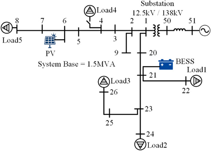
FIGURE 9. 18-node distribution network.
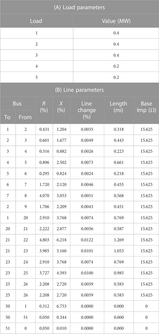
TABLE 1. Distribution network parameters.
5.1 Decrease in photovoltaic output power
The output power of the PV can decrease significantly due to changes in weather conditions. Therefore, the frequency quality deteriorates. The simulation in this section imitates that the PV panels are covered by clouds and the output power decreases to 0.4 MW at 5 s. Normally, the SG cannot respond to this amount of power in a short time, which will lead to fast frequency decrease and deviation. With reasonable control of energy storage, this situation can be improved. The simulation parameters are shown in Table 2, and the simulation results are shown in Figure 10.
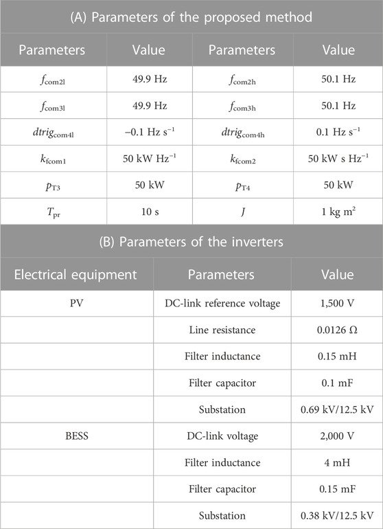
TABLE 2. Simulation parameters.
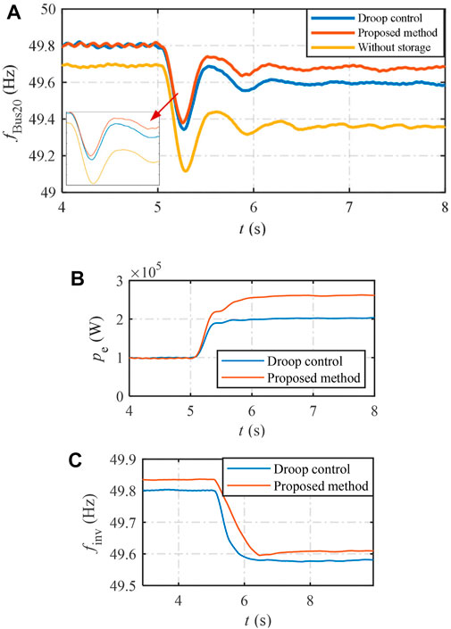
FIGURE 10. Simulation results of the output power decrease of the PV: (A) frequency of bus_20; (B) output power of the inverter; and (C) reference frequency of the inverter.
The frequency of bus_20 is shown in Figure 10A. Without the storage inverter, the bus frequency undergoes a significant decrease in the dynamic and steady states. Even the primary frequency regulation strategy of the SG improves the frequency quality, and the frequency nadir is still lower than 49.4 Hz. After the integration of the storage inverter, the bus frequency deviation decreases by 0.2 Hz with the traditional voltage-controlled droop method. As shown, the steady-state performance is enhanced with a smaller frequency deviation. The bus frequency deviation is further reduced with the proposed method. As shown, the frequency of the nadir is lowered compared with the traditional droop method. The frequency difference between the frequency nadir and steady-state frequency after 7 s is smaller with the proposed method, which is the result that it can adaptively provide extra output power according to the inverter frequency deviation and changing rate. It should be noted that the frequency in the ac bus is obtained with a PLL loop, and hence, the transient performance is influenced by the PLL bandwidth. To better observe the feature of the method in this paper, the output power and reference frequency of the inverter can be used.
The output power and reference frequency of the inverter are shown in Figures 10B, C, respectively. In the transient state, the output power evidently increases with the proposed method and decreases after that. This is because the SG cannot quickly respond to the power shortage in the transient state, and the storage inverter needs to output larger power to guarantee the power balance. Then, the input power from the prime mover of the SG can track the reference, and the output power of the storage inverter decreases. Moreover, it can be observed from the frequency point of the storage inverter that the frequency changing rate with the proposed method is smaller and, thus, proves the capability to enhance the frequency quality. In conclusion, the proposed method can provide output power more quickly than the traditional voltage-controlled method in a weak distribution network.
5.2 Photovoltaic output power increase and load increase
In this section, the increase in both the PV output power and the load is simulated to verify the influence of power disturbance from the source and load. The PV output power increases by 0.4 MW at 5 s, and the load increases by 0.2 MW at 10 s. The results are shown in Figure 11. The frequency in bus_20 is obtained with a PLL to test the frequency stability.
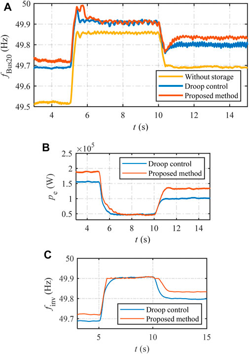
FIGURE 11. Simulation results of the output power increase and load increase of the PV: (A) frequency of bus_20; (B) output power of the inverter; and (C) reference frequency of the inverter.
The frequency change is shown in Figure 11A. After the integration of the battery storage, the frequency changing rate and deviation are both evidently decreased. In particular, in the transient state, the proposed method can output larger power to lift the frequency more quickly than the traditional frequency droop method.
The output power and output reference frequency of the inverter are shown in Figures 11B, C. Before 5 s, the frequency deviation is relatively large. With the proposed method, the storage inverter can output larger power to enhance the frequency quality. Then, between 5 s and 10 s, because of the output power of the PV increase, the power balance is guaranteed. Therefore, the extra power from the storage inverter is not required, and the output power of the traditional droop and the proposed method is the same. After 10 s, with the increase in the load, the output power of the storage inverter increases to enhance the frequency quality. In the meantime, the frequency point of the storage inverter can also show how it improves the performance of the inverter. In the transient state, the frequency change of the storage inverter is much slower, where voltage synchronization is guaranteed. With this performance, the bus frequency quality is enhanced. In conclusion, the proposed method can reduce the output power when the PV output power increases, which makes the output frequency of the inverter changes slower. It can provide power more quickly when the load increases, which makes the output frequency of the inverter change slower.
From the simulation, the proposed method can further support the frequency quality compared to the traditional voltage-controlled method by modifying the output power curve to provide extra power.
6 Conclusion
This paper establishes an equivalent transfer function model of weak distribution networks to consider the nonideal conditions of the power grid, which includes the power response delay and line impendence. The relationship among bus frequency deviation, delay, and line impendence can be reflected with this model. In our analysis, the bus frequency quality deteriorates more significantly in the weak distribution network, which has a bigger delay, line impendence, and smaller inertia. Therefore, a voltage-controlled method storage inverter is proposed to deal with the problem and improve the frequency quality in the weak distribution network, which adaptively shapes the output power curve through the deviation and changing trend of frequency. Both the bus frequency deviation and changing rate are verified as smaller in the proposed method than those in the traditional droop-controlled mode. Because the storage inverter with the proposed method can quickly output extra power, the bus frequency quality can be better enhanced when the weak distribution network encounters power disturbance from both the source and load sides.
Data availability statement
The original contributions presented in the study are included in the article/Supplementary Material; further inquiries can be directed to the corresponding author.
Author contributions
ZL and JC contributed to the theoretical analysis and model construction in Sections 2, 3. WjZ and DC wrote the manuscript and contributed to the text proofreading. SZ and TG constructed and debugged the simulation model. WZ and ZW contributed to the analysis and manuscript preparation. All authors contributed to the article and approved the submitted version.
Funding
This work was supported by the Science and Technology Project of State Grid Fujian Electric Power Company Limited (521304220008).
Conflict of interest
Authors ZL, JC, WZ, DC, SZ and TG were employed by State Grid Fujian Electric Power Research Institute. The remaining authors declare that the research was conducted in the absence of any commercial or financial relationships that could be construed as a potential conflict of interest.
The authors declare that this study received funding from the Science and Technology Project of State Grid Fujian Electric Power Company Limited (521304220008). The funder had the following involvement in the study: the decision to submit it for publication, model construction, manuscript writing and simulation.
Publisher’s note
All claims expressed in this article are solely those of the authors and do not necessarily represent those of their affiliated organizations, or those of the publisher, the editors, and the reviewers. Any product that may be evaluated in this article, or claim that may be made by its manufacturer, is not guaranteed or endorsed by the publisher.
References
Ackermann, T., Prevost, T., Vittal, V., Roscoe, A. J., Matevosyan, J., and Miller, N. (2017). Paving the way: A future without inertia is closer than you think. IEEE Power Energy Mag. 15 (6), 61–69. doi:10.1109/mpe.2017.2729138
Amaripadath, D., Roche, R., Joseph-Auguste, L., Istrate, D., Fortune, D., Braun, J. P., et al. (2017). “Power quality disturbances on smart grids: Overview and grid measurement configurations,” in 2017 52nd International Universities Power Engineering Conference (UPEC). Heraklion, Greece, August 2017.
Arco, S. D., and Suul, J. A. (2014). Equivalence of virtual synchronous machines and frequency-droops for converter-based MicroGrids. IEEE Trans. Smart Grid 5 (1), 394–395. doi:10.1109/tsg.2013.2288000
Bevrani, H., Ghosh, A., and Ledwich, G. (2010). Renewable energy sources and frequency regulation: Survey and new perspectives. IET Renew. POWER Gener. 4 (5), 438–457. doi:10.1049/iet-rpg.2009.0049
Chen, J., Yue, D., Dou, C., Li, Y., Hancke, G. P., Weng, S., et al. (2021). Distributed control of multi-functional grid-tied inverters for power quality improvement. IEEE Trans. Circuits Syst. I Regul. Pap. 68 (2), 918–928. doi:10.1109/tcsi.2020.3040253
Chowdhury, A. H., and Asaduz-Zaman, M. (2014). “Load frequency control of multi-microgrid using energy storage system,” in 8th International Conference on Electrical and Computer Engineering. Dhaka, Bangladesh, December 2014.
Dong, G., Yang, S., Chen, Y., Gao, P., Zhao, X., and Xiao, B. (2022). “Review on the influence of new energy grid connection on power quality of power grid,” in 2022 7th International Conference on Power and Renewable Energy (ICPRE). Shanghai, China, September 2022.
Fu, X., Sun, J., Huang, M., Tian, Z., Yan, H., Iu, H. H.-C., et al. (2021). Large-signal stability of grid-forming and grid-following controls in voltage source converter: A comparative study. IEEE Trans. Power Electron. 36 (7), 7832–7840. doi:10.1109/tpel.2020.3047480
Grady, W. M., Samotyj, M. J., and Noyola, A. H. (1992). The application of network objective functions for actively minimizing the impact of voltage harmonics in power systems. IEEE Trans. Power Deliv. 7 (3), 1379–1386. doi:10.1109/61.141855
Kerdphol, T., Rahman, F. S., Watanabe, M., Mitani, Y., Turschner, D., and Beck, H. P. (2019). Enhanced virtual inertia control based on derivative technique to emulate simultaneous inertia and damping properties for microgrid frequency regulation. IEEE Access 7, 14422–14433. doi:10.1109/access.2019.2892747
Lasseter, R. H., Chen, Z., and Pattabiraman, D. (2020). Grid-forming inverters: A critical asset for the power grid. IEEE J. Emerg. Sel. Top. Power Electron. 8 (2), 925–935. doi:10.1109/jestpe.2019.2959271
Liu, X., Wu, B., and Xiu, L. (2022a). A fast positive-sequence component extraction method with multiple disturbances in unbalanced conditions. IEEE Trans. Power Electron. 37 (8), 8820–8824. doi:10.1109/tpel.2022.3161734
Liu, X., Xiong, L., Wu, B., Qian, Y., and Liu, Y. (2022b). Phase locked-loop with decaying DC transient removal for three-phase grids. Int. J. Electr. Power & Energy Syst. 143, 108508. doi:10.1016/j.ijepes.2022.108508
Mathews, M. A., and Rajeev, T. (2021). “A novel power management strategy for frequency regulation in low inertia grid,” in 2021 IEEE Conference on Technologies for Sustainability (SusTech), Irvine, CA, USA, April 2021, 1–7.
Meng, L., Zafar, J., Khadem, S. K., Collinson, A., Murchie, K. C., Coffele, F., et al. (2020). Fast frequency response from energy storage systems—a review of grid standards, projects and technical issues. IEEE Trans. Smart Grid 11 (2), 1566–1581. doi:10.1109/tsg.2019.2940173
Pattabiraman, D., Lasseter, R. H., and Jahns, T. M. (2018). “Comparison of grid following and grid forming control for a high inverter penetration power system,” in 2018 IEEE Power & Energy Society General Meeting (PESGM). Portland, OR, USA, August 2018.
Shan, S., Yang, W., Xin, B., Shurong, W., and Shuxin, M. (2021). “Research on improved droop control strategy for primary frequency regulation of doubly-fed wind turbine based on gray wolf algorithm,” in 2021 3rd International Conference on Smart Power & Internet Energy Systems (SPIES). Shanghai, China, September 2021.
Swierczynski, M., Stroe, D. I., Stan, A. I., Teodorescu, R., and Ieee, (2013). “Primary frequency regulation with Li-ion battery energy storage system: A case study for Denmark,” in 2013 IEEE ECCE ASIA DOWNUNDER (ECCE ASIA), Melbourne, VIC, Australia, June 2013, 487–492.
Wang, Y., Xu, Y., Tang, Y., Liao, K., Syed, M. H., Guillo-Sansano, E., et al. (2019). Aggregated energy storage for power system frequency control: A finite-time consensus approach. IEEE Trans. Smart Grid 10 (4), 3675–3686. doi:10.1109/tsg.2018.2833877
Wang, Z., Yi, H., Jiang, Y., Bai, Y., Zhang, X., Zhuo, F., et al. (2022). Voltage control and power-shortage mode switch of PV inverter in the islanded microgrid without other energy sources. IEEE Trans. Energy Convers. 37 (4), 2826–2836. doi:10.1109/tec.2022.3188334
Wang, Z., Yi, H., Zhuo, F., Wu, J., and Zhu, C. (2021). Analysis of parameter influence on transient active power circulation among different generation units in microgrid. IEEE Trans. Industrial Electron. 68 (1), 248–257. doi:10.1109/tie.2019.2962447
Wang, Z., Zhuo, F., Yi, H., Wu, J., Wang, F., and Zeng, Z. (2019). Analysis of dynamic frequency performance among voltage-controlled inverters considering virtual inertia interaction in microgrid. IEEE Trans. Industry Appl. 55 (4), 4135–4144. doi:10.1109/tia.2019.2910784
Xie, Y., Huang, J., Liu, X., Zhuo, F., Liu, B., and Zhang, H. (2014). “PV system modeling and a global-planning design for its controller parameters,” in 2014 IEEE Applied Power Electronics Conference and Exposition - APEC 2014. Fort Worth, TX, USA, March 2014.
Xiong, L., Liu, L., Liu, X., and Liu, Y. (2021). Frequency trajectory planning based strategy for improving frequency stability of droop-controlled inverter based standalone power systems. IEEE J. Emerg. Sel. Top. Circuits Syst. 11 (1), 176–187. doi:10.1109/jetcas.2021.3052006
Yang, P., Dong, X., Li, Y., Kuang, L., Zhang, J., He, B., et al. (2019). Research on primary frequency regulation control strategy of wind-thermal power coordination. IEEE Access 7, 144766–144776. doi:10.1109/access.2019.2946192
Ye, H., Pei, W., and Qi, Z. (2016). Analytical modeling of inertial and droop responses from a wind farm for short-term frequency regulation in power systems. IEEE Trans. Power Syst. 31 (5), 3414–3423. doi:10.1109/tpwrs.2015.2490342
Keywords: frequency quality, weak distribution network, storage inverter, voltage-controlled mode, adaptive power demand
Citation: Li Z, Chen J, Zhang W, Chen D, Zhang S, Gao T, Zhang W and Wang Z (2023) Adaptive frequency deviation improvement using a voltage-controlled storage inverter in a weak distribution network with a high penetration level of stochastic photovoltaic power. Front. Energy Res. 11:1219227. doi: 10.3389/fenrg.2023.1219227
Received: 08 May 2023; Accepted: 12 June 2023;
Published: 22 June 2023.
Edited by:
Xiaokang Liu, Polytechnic University of Milan, ItalyReviewed by:
Baojin Liu, Fuzhou University, ChinaShuhuai Shi, State Grid Henan Electric Power Research Institute, China
Copyright © 2023 Li, Chen, Zhang, Chen, Zhang, Gao, Zhang and Wang. This is an open-access article distributed under the terms of the Creative Commons Attribution License (CC BY). The use, distribution or reproduction in other forums is permitted, provided the original author(s) and the copyright owner(s) are credited and that the original publication in this journal is cited, in accordance with accepted academic practice. No use, distribution or reproduction is permitted which does not comply with these terms.
*Correspondence: Dawei Chen, ZHdjaGVuQHpqdS5lZHUuY24=