 Myung Jin Jeong
 Jaeuk Im
 Hyoung Kyu Cho
- Department of Nuclear Engineering, Seoul National University, Seoul, Republic of Korea
Heat-pipe-cooled microreactors (HPRs) have advantages such as a compact design, easy transportation, and improved system reliability and stability. The core of an HPR consists of fuel rods and heat pipes in a monolith, which is a solid block structure containing many holes for the fuel rods and heat pipes. When designing the core of an HPR, high thermal stress and reactivity feedback owing to thermal expansion are important considerations. Therefore, a high-fidelity multiphysics analysis tool is required for accurately analyzing an HPR core. When performing a multiphysics analysis, it is necessary to couple the heat pipe thermal analysis code, thermal-structural analysis code, and neutronics code. To develop a multiphysics analysis tool, OpenFOAM, an open source Computational Fluid Dynamics (CFD) tool, and ANLHTP, a heat pipe thermal analysis code, were coupled. In this process, the structural analysis solver of OpenFOAM was verified, and its limitations were improved. To confirm the proper working of the code, the mini-core problem was analyzed using the OpenFOAM-ANLHTP coupled code. Next, to consider the reactivity feedback, coupling with PRAGMA, a GPU-based continuous-energy-Monte Carlo neutronics code was performed, and the multiphysics analysis capability of the OpenFOAM-ANLHTP-PRAGMA coupled code was confirmed through an analysis of the MegaPower reactor core. To reduce the temperature distribution within the monolith, the temperature distribution of the heat pipe sink was adjusted, and the reduced thermal stress of an HPR core was observed.
1 Introduction
A heat pipe cooled microreactor (HPR) is a nuclear reactor that passively removes heat from a core using heat pipes. The heat pipe is a passive heat-transfer device using the capillary force of the wick structure and phase transition. The heat pipe is filled with a working fluid, and the working fluid transfers heat as it evaporates at the evaporator section and condenses at the condenser section. An HPR has the advantages of compact design, ease of transport, and improved system reliability and stability. It has attracted attention among various microreactor concepts since the success of the Kilopower Reactor Using Stirling TechnologY (KRUSTY) experiment (Gibson et al., 2018). Since then, space reactors and land-based reactors such as the Los Alamos National Laboratory (LANL)’s Megapower reactor (Mcclure et al., 2015), the Westinghouse’ eVinci (Swartz et al., 2021), Oklo’s Aurora (OKLO Inc., 2020), and China’s NUSTER-100 (Tang et al., 2022) have been studied.
The representative form of an HPR core comprises many heat pipes, and fuel rods, which are contained in a solid structure called the monolith. The heat generated from the nuclear fuel is transferred to the heat pipes through the monolith via conduction, and the heat pipe transfers heat from the core to the power conversion system.
A land-based HPR with several MWe of power requires the integration of many nuclear fuels and heat pipes in the small space of the monolith. This spatial integration increases the temperature gradient within the monolith and may induce high thermal stress. This high thermal stress is one of the critical issues in the core design of existing monolith-based HPRs. Additionally, the thermal expansion of a metal monolith results in reactivity feedback owing to the change in neutron leakage, especially in fast reactors. Neutronics analysis has revealed that most reactivity feedback is due to such thermal expansions (Hu et al., 2019).
To reflect the consideration of these variations in the design and safety analysis of an HPR core, a high-fidelity multiphysics analysis tool is required. Accordingly, the Idaho National Laboratory (INL) conducted a PIRT analysis of the Megapower reactor (Sterbentz, 2017), and developed Direwolf (Lange, 2020), a heat pipe reactor multiphysics analysis tool, using the Multiphysics Object-Oriented Simulation Environment (MOOSE); Direwolf can perform neutronics-thermal-structural analysis. Additionally, steady-state and transient multiphysics analyses have been performed on the EMPIRE core (Matthews et al., 2021).
The Korea Atomic Energy Research Institute (KAERI) developed a heat pipe code called LUHPIS (Tak et al., 2020), and performed a thermal analysis of two conceptual heat pipe cooled reactor cores using LUHPIS and HEPITOS coupled code (Lee et al., 2021). The Argonne National Laboratory (ANL) performed the PROTEUS-FLUENT-ANLHTP coupled analysis in cooperation with the Seoul National University (SNU) (Lee et al., 2019). Additionally, steady-state and transient multiphysics analyses were performed on an HP-MR reactor using the MOOSE platform (Stauff et al., 2021). The Xi’an Jiaotong University performed steady-state and transient multiphysics analyses on the NUSTER-100 core (Huang et al., 2022; Tang et al., 2022) and validation calculations for the KRUSTY experiment (Ge et al., 2022).
Thermal-structural analysis of the monolith in an HPR is necessary in HPR core analysis for confirming whether safety criteria such as the fuel centerline temperature and maximum thermal stress in the monolith are satisfied. For this purpose, OpenFOAM was selected for the thermal-structural analysis of the monoliths in this study. OpenFOAM is an open-source CFD software that has a built-in basic structural analysis solver. Additionally, studies in the nuclear community have been conducted using the OpenFOAM solver (Fiorina et al., 2015; Scolaro et al., 2020). Since OpenFOAM is open-source software, its solver could be modified and improved easily, and could be coupled easily it with other codes. Taking these advantages of OpenFOAM, Tsinghua University performed multiphysics analysis of KRUSTY using the OpenFOAM-RMC code (Guo et al., 2021; Guo et al., 2022).
In this study, a multiphysics simulation was conducted to develop a high-fidelity multiphysics analysis tool for HPRs. The OpenFOAM stress analysis solver was coupled with the Monte Carlo neutron transport code PRAGMA and the heat pipe analysis code ANLHTP. The applicability of the coupled code was tested through an analysis of two types of microreactor cores from existing literature. Subsequently, based on the simulation results, a strategy to reduce the thermal stress in a monolith is proposed. The simulation results showed that the uniformity of the temperature field in the monolith could significantly reduce the thermal stress, which could be achieved by adjusting the heat sink temperature of the heat pipes. This suggested that the heat sink temperature distribution could be an optimization parameter in HPR core design.
This study introduces the verification results of the OpenFOAM stress analysis solver, the coupling methodology for the multiphysics simulation, and the specifications of PRAGMA and ANLHTP. Subsequently, the application of the coupled code to reactor core analyses is presented. Finally, the effect of heat sink temperature adjustment on thermal stress reduction is described.
2 Establishment of OpenFOAM-ANLHTP code coupling system
2.1 OpenFOAM
The OpenFOAM code was selected as a tool in the thermal-structural analysis of an HPR core. OpenFOAM is an open-source-based CFD tool that has a built-in basic thermal-structural analysis solver (The OpenFOAM Foundation Ltd., 2019, Accessed 2023). This solver enables the thermal-structural analysis of small deformation conditions under the assumption of linear elasticity. This assumption does not consider plastic deformation after yielding; however, it is effective and sufficient in determining whether an HPR core reaches the yield strength. The governing equations are expressed as Eqs 1, 2:
Momentum equation
where
Heat conduction equation
where
According to the official OpenFOAM user guide, this solver has been verified against simple structural analysis problems; however, no such verification has been reported for thermal stress. Furthermore, the temperature dependencies of the material properties have not been considered by the solver, and multiple-material handling, which is necessary for reactor core analysis, could not be carried out. Therefore, in this study, various improvements were made to the solver.
First, the thermal-structural analysis was verified. The verification problems were selected from the Autodesk Nastran verification manual (Autodesk Inc., 2015) and the ANSYS Mechanical APDL verification manual (ANSYS Inc., 2013).
The concepts of the verification problems and calculation results are illustrated in Figure 1. The first problem is constrained beam analysis with heating. Two cases were tested under single-end and both-end constraint boundary conditions. In both cases, the body temperature was increased from −50°C to 25°C. The predicted values of the displacement and axial stress were compared with the values in the analytical solution. The second problem is the steady-state calculation of a cylinder, with a linear temperature difference gradient between its inner and outer surfaces. The final problem is the transient calculation of the cylinder, wherein the outer surface temperature increases gradually. In the second and third cases, the stresses on the inner and outer surfaces were compared with the analytical solutions. For three verification problems, as the number of meshes increased, the solutions gradually converged to the analytical solutions. The thermal-structural analysis capability of the solver was confirmed through these simple verifications.
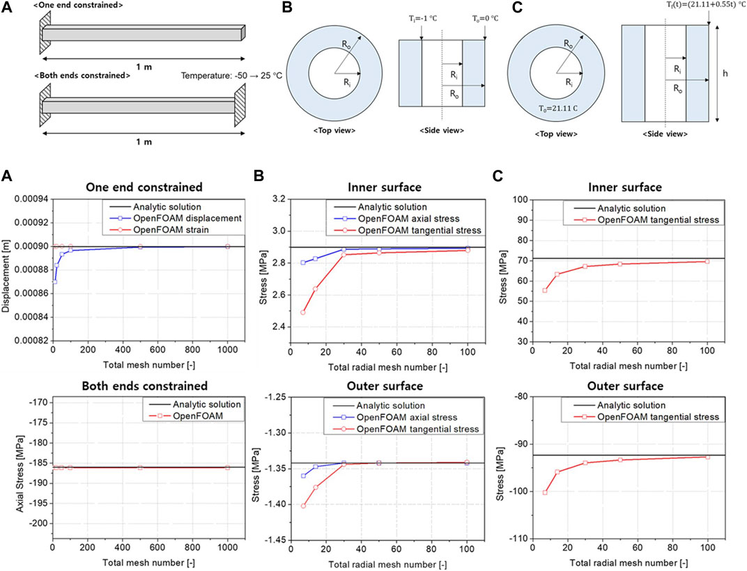
FIGURE 1. Conceptual representations and calculation results (A) constrained heated beam, (B) cylinder with thermal gradient (steady-state), and (C) cylinder with thermal gradient (transient).
Subsequently, the capabilities of the solvers were extended to consider the temperature dependencies of structural materials and multiple-material handling. Therefore, a new field variable containing the material type was defined for each cell. Additionally, another field variable storing the volumetric heat generation rate was defined, and this value was added to the variable transferable from the external solver, considering the coupling of the code with a neutronics code.
2.2 Heat pipe analysis code, ANLHTP
ANLHTP is a one-dimensional steady-state thermal analysis code for sodium heat pipes (McLennan, 1983). The source code is available in existing literature, and the code used in the study was resurrected based on it (Lee et al., 2019). ANLHTP is a simple and fast lumped parameter code, and using a thermal resistance network, it predicts the heat transfer rate, temperature at each part, and operation limits of the heat pipe. The validation was performed against the ANL HPTF experiment (Holtz et al., 1985) and LASL experiment (Kemme et al., 1978); the heat pipe heat removal performance and operation limits were compared with those under these experiments. The details of the heat pipe specifications and experimental setup are presented in Ref. (Kemme et al., 1978; Holtz et al., 1985). The validation results confirmed that ANLHTP has reasonably predicted the heat pipe performance and operating limits and that the code had been correctly resurrected (Lee et al., 2019).
2.3 OpenFOAM-ANLHTP data exchange
The coupling of OpenFOAM and ANLHTP was established for the thermal-structural analysis of the HPR core. The coupled code used the coupling interface provided by OpenFOAM for external coupling (The OpenFOAM Foundation Ltd., Accessed 2023). Additionally, a Python wrapper code was developed to manipulate the data from the two codes. OpenFOAM sent the heat transfer rate field to the coupling boundary of the wrapper. Averages were then obtained for each part of the heat pipe, such as the evaporator, adiabatic section, and condenser. The averaged values were transferred from the wrapper to ANLHTP. ANLHTP calculates the temperatures of the three parts, returns them to the wrapper, and assigns these values to the meshes in each part; the three-dimensional code and lumped parameter code. This implied that the average heat transfer rate values in the multiple boundary faces of OpenFOAM were used for ANLHTP, and a single temperature value in each part of the heat pipe was used for the multiple boundary faces. This difference in the simulation dimensions can distort practical changes in parameters.
To minimize this distortion, the wick-vapor interface of the heat pipe evaporator was set as the data exchange interface, as shown in Figure 2. The temperature at the wick-vapor interface was assumed to have an insignificant temperature variation along the axis because its temperature was close to the saturation temperature in the vapor core. Using this method, the axially non-uniform heat transfer rate could be considered using the lumped parameter code ANLHTP (Zuo and Faghri, 1998).
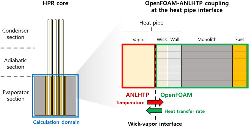
FIGURE 2. OpenFOAM-ANLHTP data exchange at the wick-vapor interface of the heat pipe.
2.4 Demonstration: mini-core problem
To demonstrate the capabilities of the OpenFOAM-ANLHTP, a mini-core problem was devised. The objective of the simulation was to verify whether the coupled code worked reasonably well under steady-state conditions. The mini-core problem is a conceptual problem referring to a non-nuclear testbed, such as the MAGNET experimental device (Morton et al., 2020). The mini-core is a 1-m height core containing 55 heat pipes and 84 fuel rods, and the helium gap exists between the fuel rod and monolith. Figure 3 shows the total geometry and computational mesh of the mini-core, and Table 1 shows the specifications and configuration of the mini-core. The arrangement of the heat pipes and fuel rods, including the diameter and pitch between them, followed that of the Megapower reactor (Mcclure et al., 2015). The thermal powers of each fuel rod and the reactor core were 1573 W and 132 kW, respectively. Following the first multiphysics conceptual problem, a uniform power distribution along the axis was assumed for the steady-state analysis. The screen wick of the heat pipe was referred to as the heat pipe of NASA (Reid, 2004), and the size and heat sink temperature of the heat pipe were referred to as the heat pipe of the Megapower reactor.
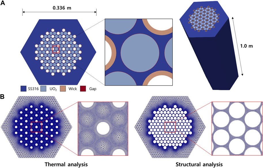
FIGURE 3. (A) Geometry and (B) computational mesh of the mini-core problem.
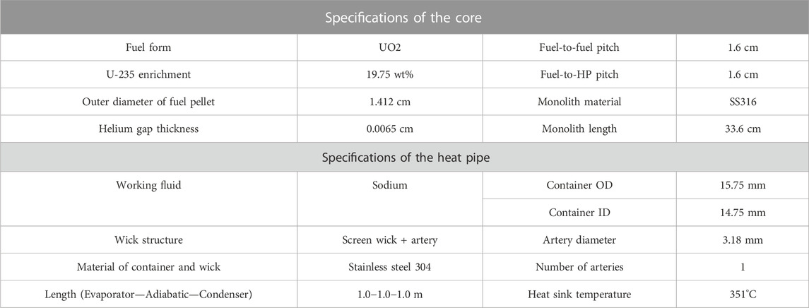
TABLE 1. Specific geometry and configuration of the mini-core.
Regarding the thermal analysis using OpenFOAM, all boundaries except the heat pipe boundaries were set to adiabatic conditions. For the heat pipe boundaries, temperature boundary conditions were imposed; these conditions were obtained from the heat pipe thermal analysis using ANLHTP for each heat pipe. For the given boundary temperatures, the temperature field in the monolith was obtained, and the heat flux was evaluated for the heat pipe boundaries. The heat flux of each heat pipe was considered when conducting ANLHTP analyses on the heat pipes. Following the ANLHTP calculations, the temperature boundary conditions were updated for the next iteration. This procedure was repeated until the temperature field converged, following which the temperature field was transferred to the structural analysis solver. Since the concern of the structural analysis is the thermal stress in the monolith region, the computational domain of the analysis was limited to this region. Regarding the boundary conditions, a normally fixed condition was imposed on the bottom surface.
Thermal-structural analysis using the OpenFOAM-ANLHTP coupled code was performed to check the mesh convergence. The analysis results with three different meshes are presented in Figure 4A; the convergence of the maximum temperature and von Mises stress in the monolith was observed. Based on these results, the simulations were performed using the mesh size in case (c). Meanwhile, the maximum thermal stress was 200.8 MPa, exceeding the yield strength of SS316, which was 100 MPa at 700°C. This was because the problem was conceptually designed for coupled thermal-neutronics analysis; structural integrity aspects such as the thermal stress were not the primary concern. Figure 4B shows the wick-vapor interface temperature and heat removal rate of the heat pipes in the mini-core problem. We observed a high heat removal rate and temperature in the central region and a decreasing trend toward the outside that caused a temperature difference within the monolith.
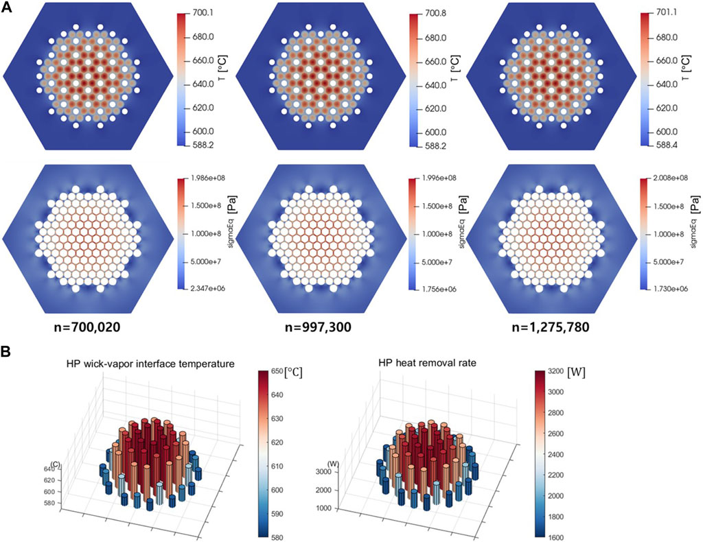
FIGURE 4. (A) Steady-state thermal-structural analysis results (B) interface temperature and heat removal rate of heat pipes for the mini-core problem.
One of the main causes of high thermal stress was the relatively low temperature in the thick outer monolith region, which acted as a resistance to thermal expansion. To solve this problem, the mini-core geometry was modified to minimize the low-temperature region; the outer area of the reactor core edge was chopped off. Figure 5A presents the modified geometry assuming that the reflector surrounding the reactor core had a sufficient gap to dampen thermal expansion. However, if the outer monolith is too thin, thermal stress can increase at the outer monolith. Therefore, to find the optimal size of the monolith to reduce the maximum thermal stress, a parametric study of the monolith size was performed.
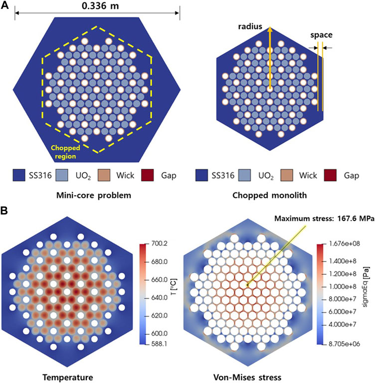
FIGURE 5. (A) Geometry and (B) thermal-structural analysis results (radius 0.133 m) of the mini-core with a chopped monolith.
The same thermal-structural analysis was repeated for the chopped monolith geometry with various distances between the heat pipes and the outer periphery of the monolith, and the results are shown in Table 2. If the distance is too short, the stress in the outer area of the monolith becomes higher than that at the center. When the radius of the monolith was 0.133 m, the stress at both locations were similar. If the monolith radius is further increased, the stress at the center is expected to increase and gradually approach that of the original geometry. Also, as shown in Figure 5B, while the temperature distribution was almost the same as that of the original geometry, the maximum thermal stress was reduced from 200.8 to 167.6 MPa at the center. This implied that the outer space of the monolith needed to be considered during the design optimization process. The simulation of this conceptual problem revealed that the coupled code worked properly and that the convergence of the coupled simulation could be achieved stably.
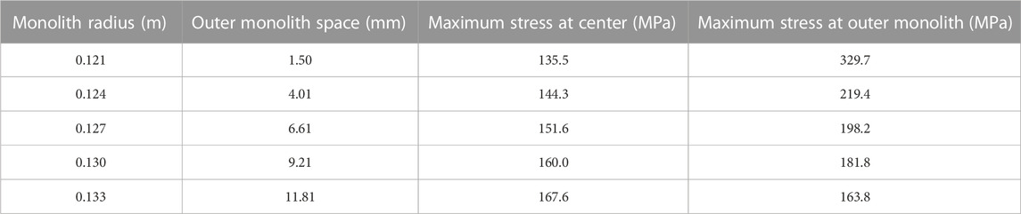
TABLE 2. Parametric study on the size of the monolith.
3 OpenFOAM-ANLHTP-PRAGMA coupled code system
The aforementioned simulation was conducted using coupled OpenFOAM and ANLHTP, which imposed a uniform heat generation rate to the core. For a more realistic simulation of the power distributions in the axial and radial directions, neutronics code coupling was required. In this study, a Monte Carlo neutron transport code, PRAGMA, was coupled with the other codes for the multiphysics simulations.
PRAGMA is a GPU-accelerated continuous energy Monte Carlo neutronics code developed by Seoul National University and was originally designed to perform simulations for power reactors (Choi et al., 2021). To analyze irregular and complex shapes such as the HPR core, PRAGMA exploits a hardware-accelerated ray tracing library to track neutrons in an unstructured mesh geometry (Im et al., 2023). It can conduct many particle simulations on NVIDIA CUDA-enabled GPU cards with a reasonable timescale. For the efficient coupling of the GPU and CPU parallelization schemes, the coupling system was established by employing an MPI dynamic process management mode, wherein manager-worker parallelism was maintained, as shown in Figure 6. Both PRAGMA and OpenFOAM were linked to their respective workers as dynamic libraries, and their workers communicated through the manager. The wrapper script for the OpenFOAM and ANLHTP coupling was executed in the background by the manager. For the reactivity feedback, OpenFOAM provided the temperature and density, and PRAGMA calculated the power from the received temperature and density fields.
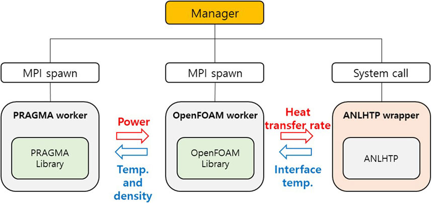
FIGURE 6. Manager-worker system of OpenFOAM-ANLHTP-PRAGMA.
The Megapower reactor core was analyzed to demonstrate the capability of the OpenFOAM-ANLHTP-PRAGMA coupled code. For the steady-state analysis, 1/6 section of the reactor core was considered for the computational domain. The Megapower reactor is an HPR design suggested by LANL. The geometry and computational mesh of the sectioned Megapower reactor core are shown in Figure 7. It included 352 fuel rods and 204 heat pipes, and the total power of the 1/6 section core was 833 kW. Sodium was selected as the working fluid of the heat pipe. The geometry and specifications of the heat pipe were the same as those used in the mini-core problem, except that the evaporator length was 1.5 m. Like the mini-core problem, all the boundaries, except for the heat pipe boundary, were set to adiabatic conditions, and the structural analysis was conducted with a normally fixed bottom surface.
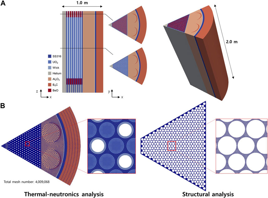
FIGURE 7. (A) Geometry and (B) computational mesh of the Megapower reactor.
The results of the multiphysics analysis are shown in Figure 8. A cosine-shaped power distribution in the axial direction, maximum power in the center, and power increase in the radial direction near the outer reflector were observed. Regarding the uncertainty of power distribution of PRAGMA, RMS averaged mesh-wise power uncertainty was 0.318%. The maximum temperatures of the fuel rod and monolith were 859.1° and 798.3°C, respectively. The total heat generation rate of PRAGMA and OpenFOAM, and heat removal rate of ANLHTP were consistent within a difference of a maximum 3 W, confirming that the variable exchange between the coupled codes is working well. The high temperature of the monolith could decrease the yield strength, resulting in the deterioration of the structural integrity of the monolith. One reason for the high temperature of the monolith was that the working fluid of the heat pipe was sodium, which has a higher working temperature than potassium, the actual working fluid in the Megapower reactor design. Hence, to reduce the temperature, additional optimizations, such as changing the working fluid or modifying the heat pipe design, can be considered. A maximum thermal stress of 345.5 MPa appeared in the corner region of the monolith, exceeding 100 MPa, which was the yield strength of SS316 at that temperature.
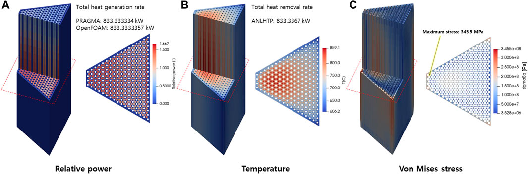
FIGURE 8. Analysis results of the Megapower reactor (A) power (B) temperature (C) stress.
4 Parametric study on the heat sink temperature of heat pipes
The reasons for the high thermal stress shown in the mini-core and Megapower reactor core calculations were temperature difference within the monolith and the geometry. Figure 9 shows the temperature and stress distributions at the point where the maximum thermal stress appeared in the mini-core. A large temperature gradient was observed between the fuel rods and heat pipes in a narrow region between the fuel rods. Therefore, it was necessary to reduce the temperature difference or extend the distance between the fuel rods and heat pipes to reduce thermal stress. However, it is difficult to improve the geometry of the core because its small size is a requirement for transportation. Therefore, to flatten the temperature within the monolith, the heat removal rate of the heat pipes was controlled. In this paper, the sink temperatures of the heat pipes were partially adjusted to control the heat removal rate.
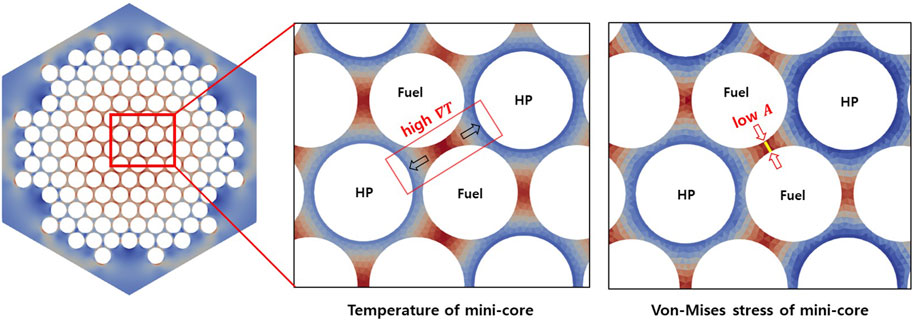
FIGURE 9. Temperature and stress at the maximum thermal stress region of the mini-core.
4.1 Cases of parametric study
To evaluate the thermal stress due to the temperature difference within the monolith and confirm the effect of adjusting the heat sink temperature, four simulations were conducted depending on the application of a realistic power distribution, heat pipe code coupling, and heat sink temperature adjustment, as listed in Table 3.
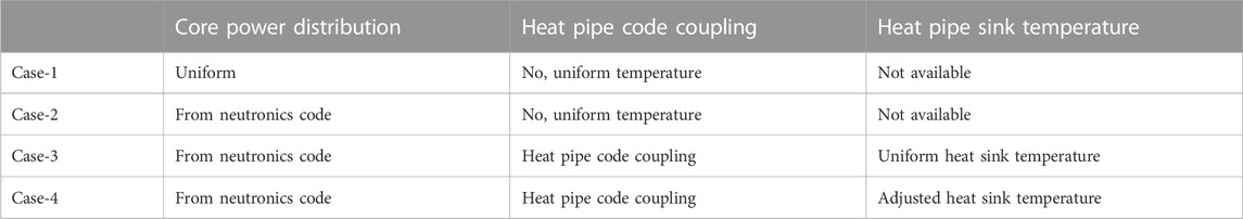
TABLE 3. Calculation conditions of parametric study.
Case 1 is the simplest condition for comparison, where a uniform power distribution is applied, and the heat pipe interface temperature is assumed to be constant at all locations. From Case-1 to Case-2, the power distribution obtained from the PRAGMA was applied, which increased the temperature difference within the monolith as more heat was generated locally in some fuel rods; this increased the thermal stress in the monolith. From Case-2 to Case-3, non-uniform heat pipe interface temperatures were applied at every heat pipe as the heat pipe code was coupled. The temperature difference in the monolith was expected to increase as a higher heat pipe interface temperature would be applied at a region where high heat generation rate was applied. This resulted in an increased thermal stress in the monolith. Finally, to reduce the increased thermal stress in Case-2 and Case-3 and flatten the temperature field in the monolith, the heat sink temperatures at each heat pipe were adjusted in Case-4. The heat pipes were divided into five or six groups based on their locations, and different heat sink temperatures were imposed depending on the groups. Higher temperature conditions were applied where the monolith temperature was lower, and vice versa. It was expected that the temperature difference in the monolith could be reduced with this adjustment because more and less heat could be removed when the monolith temperature was higher and lower, respectively. The heat pipe groupings for the mini-core and sectioned core of the Megapower reactor are shown in Figure 10. Regarding the Megapower, adiabatic conditions were used for the two heat pipes at the corner, wherein a high thermal stress appeared owing to relatively low temperatures. The imposed heat sink temperatures are shown in Figure 10.
FIGURE 10. Heat pipe grouping for the heat sink temperature adjustment.
4.2 Parametric study result
The thermal-structural analysis results for each condition for the mini-core and Megapower reactor are shown in Table 4 and Figure 11 shows the comparison results between Cases-3 and 4 in the two geometries. Compared to Case-1, wherein a uniform power distribution and constant heat pipe interface temperature were used, the temperature difference and maximum thermal stress within the monolith increased when the power distribution obtained using PRAGMA was applied (Case-2), and the heat pipe code was coupled (Case-3). Particularly, the maximum temperature difference in the monolith increased remarkably for both geometries when the heat pipe code was coupled (Case-3). When the heat sink temperatures were adjusted depending on the groups (Case-4), the temperature field was relatively flattened as shown in Figure 11, and the temperature difference was reduced, as shown in Table 4. Consequently, the thermal stress within the monolith decreased. These results implied that the non-uniform heat removal rate of heat pipes, depending on their location and monolith temperature, could reduce the thermal stress in the monolith core. The heat sink design of the heat pipes needs to be considered as one of the optimization parameters because an appropriate design can reduce the thermal stress in the monolith without modifying the core geometry, and the issue of high thermal stress is one of the challenges in designing a monolith core type microreactor.
TABLE 4. Thermal-structural analysis results of the mini-core and Megapower reactor.
FIGURE 11. Thermal-structural analysis results of the mini-core and Megapower (Case-3 and Case-4).
5 Conclusion
In this study, a multiphysics analysis tool was developed for an HPR core. First, OpenFOAM and ANLHTP were coupled to establish a thermal-structural analysis system. To demonstrate the thermal-structural analysis capability of the OpenFOAM-ANLHTP coupled code, a steady-state analysis of the mini-core problem was conducted; a high thermal stress was observed in the monolith. To reduce the high thermal stress of the mini-core, a chopped monolith problem was newly defined, and it was confirmed that the thermal stress could be reduced through geometry modification.
Next, coupling with PRAGMA was performed to establish a neutronic-thermal-structural analysis system. To demonstrate the multiphysics analysis capability of the coupled code, a steady-state analysis was performed on the Megapower reactor core, and the coupled code showed physically proper results. However, both the mini-core and the Megapower reactor core exhibited high thermal stress exceeding the yield strength of the monolith. Therefore, to reduce the temperature difference within the monolith, which caused the high thermal stress, a heat pipe sink temperature distribution was applied. With the adjusted heat pipe sink temperature, it was confirmed that thermal stress could be reduced by decreasing the temperature difference within the monolith.
In the future, the coupled code can be used for the design and optimization of HPR cores. Necessary improvements in the coupled codes include transient analysis capability, and mesh deformation for a more realistic neutron leakage evaluation. Particularly, the VandV of each code was separately conducted before the coupling, and the capability of the coupled code has been demonstrated. However, the validation of multi-physics analysis capability of a monolith type HPR core is necessary and will be performed in the future when the required information for the modelling becomes available. Additionally, heat pipe experiments with a monolith are planned for producing validation data.
Data availability statement
The original contributions presented in the study are included in the article/supplementary material, further inquiries can be directed to the corresponding author.
Author contributions
MJ, JI, SL, and HC contributed to conception and design of the study. MJ, JI, and SL carried out the code coupling. MJ and JI carried out the multiphysics analysis using coupled code. MJ, JI, and HC contributed to the interpretation of the simulation results. MJ wrote the first draft of the manuscript. MJ, JI, SL, and HC contributed to manuscript revision, read, and approved the submitted version.
Funding
This work was supported by the National Research Foundation of Korea (NRF) grant funded by the Korea government (Ministry of Science and ICT) (Nos 2020M2D2A1A02066317, 2021M2D6A1048220).
Conflict of interest
The authors declare that the research was conducted in the absence of any commercial or financial relationships that could be construed as a potential conflict of interest.
Publisher’s note
All claims expressed in this article are solely those of the authors and do not necessarily represent those of their affiliated organizations, or those of the publisher, the editors and the reviewers. Any product that may be evaluated in this article, or claim that may be made by its manufacturer, is not guaranteed or endorsed by the publisher.
References
Autodesk Inc, (2015). Autodesk® Nastran® 2016 verification manual. San francisco, CA, USA: Autodesk.
Choi, N., Kim, K. M., and Joo, H. G. (2021). Optimization of neutron tracking algorithms for GPU-based continuous energy Monte Carlo calculation. Ann. Nucl. Energy 162, 108508. doi:10.1016/j.anucene.2021.108508
Fiorina, C., Clifford, I., Aufiero, M., and Mikityuk, K. (2015). GeN-foam: A novel OpenFOAM®based multiphysics solver for2D/3D transient analysis of nuclear reactors. Nucl. Eng. Des. 294, 24–37. doi:10.1016/j.nucengdes.2015.05.035
Ge, L., Li, H., Tian, X., Ouyang, Z., Kang, X., Li, D., et al. (2022). Improvement and validation of the system analysis model and code for heat-pipe-cooled microreactor. Energies 15 (7), 2586. doi:10.3390/en15072586
Gibson, M. A., Poston, D., Mcclure, P., Godfroy, T. J., Briggs, M. H., and Sanzi, J. L. (2018). “Kilopower reactor using stirling technology (krusty) nuclear ground test results and lessons learned,” in Proceedings of the 2018 International Energy Conversion Engineering Conference, Cincinnati, Ohio, July 2018. doi:10.2514/6.2018-4973
Guo, Y., Li, Z., Huang, S., Liu, M., and Wang, K. (2021). A new neutronics-thermal-mechanics multi-physics coupling method for heat pipe cooled reactor based on RMC and OpenFOAM. Prog. Nucl. Energy 139, 103842. doi:10.1016/j.pnucene.2021.103842
Guo, Y., Li, Z., Wang, K., and Su, Z. (2022). A transient multiphysics coupling method based on OpenFOAM for heat pipe cooled reactors. Sci. China Technol. Sci. 65, 102–114. doi:10.1007/s11431-021-1874-0
Holtz, R. E., McLennan, G. A., and Koehl, E. R. (1985). On the experimental operation of a sodium heat pipe. Lemont, IL, USA: Argonne National Laboratory. doi:10.2172/5100887
Hu, G., Hu, R., Kelly, J. M., and Ortensi, J. (2019). Multiphysics simulations of heat pipe micro reactor. Lemont, IL, USA: Argonne National Laboratory. doi:10.2172/1569948
Huang, J., Wang, C., Tian, Z., Guo, K., Su, G. H., Tian, W., et al. (2022). Preliminary conceptual design and analysis of a 100 kW e level Nuclear Silent Thermal-Electrical Reactor (NUSTER -100). Int. J. Energy Res. 46 (14), 19653–19666. doi:10.1002/er.8542
Im, J., Jeong, M. J., Kim, K. M., Cho, H. K., and Joo, H. G. (2023). Multiphysics analysis system for heat pipe cooled micro reactors employing PRAGMA-OpenFOAM-ANLHTP. Nucl. Sci. Eng. 26. doi:10.1080/00295639.2022.2143209
Kemme, J. E., Keddy, E. S., and Phillips, J. R. (1978). “Performance investigations of liquid-metal heat pipes for space and terrestrial applications,” in Proceedings of the 3rd International Heat Pipe Conference, Palo Alto,CA,USA, May 1978.
Lange, T. (2020). Experience with DireWolf for heat-pipe microreactor analysis to support early demonstration. Idaho Falls, ID, USA: Idaho national laboratory.
Lee, C. H., Jung, Y. S., and Cho, H. K. (2019). Micro reactor simulation using the PROTEUS suite in FY19. Lemont, IL, USA: Argonne National Laboratory. doi:10.2172/1571248
Lee, S. N., Choi, S. H., and Kim, C. S. (2021). “Development of heat transfer analysis code for heat pipe cooled space reactor core,” in Proceedings of the Transactions of the Korean Nuclear Society Spring Meeting, Kyeongju, Korea, May 2021.
Matthews, C., Laboure, V., DeHart, M., Hansel, J., Andrs, D., Wang, Y., et al. (2021). Coupled multiphysics simulations of heat pipe microreactors using Direwolf. Nucl. Technol. 207 (7), 1142–1162. doi:10.1080/00295450.2021.1906474
Mcclure, P. R., Poston, D. I., Dasari, V. R., and Reid, R. S. (2015). Design of megawatt power level heat pipe reactors. Los Alamos, NM, USA: Los Alamos National Lab. doi:10.2172/1226133
McLennan, G. A. (1983). ANL/HTP: A computer code for the simulation of heat pipe operation. Lemont, IL, USA: Argonne National Laboratory.
Morton, T. J., O’Brien, J. E., and Hartvigsen, J. L. (2020). Functional and operating requirements for the microreactor agile non-nuclear experimental test bed (MAGNET). Idaho Falls, ID, USA: Idaho National Lab.
Oklo Inc, (2020). Part II: Final safety analysis report. https://www.nrc.gov/docs/ML2007/ML20075A003.pdf.
Reid, R. S. (2004). Alkali metal heat pipe life issues. Proceedings of the 2004 International Congress on Advances in Nuclear Power Plants, La Grange Park, IL, USA, June 2004.
Scolaro, A., Clifford, I., Fiorina, C., and Pautz, A. (2020). The OFFBEAT multi-dimensional fuel behavior solver. Nucl. Eng. Des. 358, 110416. doi:10.1016/j.nucengdes.2019.110416
Stauff, N., Mo, K., Cao, Y., Thomas, J., Miao, J., Zou, L., et al. (2021). Detailed analyses of a TRISO-fueled microreactor. Lemont, IL, USA: Argonne National Laboratory. doi:10.2172/1826285
Sterbentz, J. W., Werner, J. E., McKellar, M. G., Hummel, A. J., Kennedy, J. C., Wright, R. N., et al. (2017). Special purpose nuclear reactor (5 MW) for reliable power at remote sites assessment report using phenomena identification and ranking tables (PIRTs). Idaho Falls, ID, USA: Idaho national laboratory. doi:10.2172/1410224
Swartz, M. M., William, A. B., John, L., and Rory, B., (2021). Westinghouse evinci™ heat pipe micro reactor technology development. Proceedings of the 2021 28th International Conference on Nuclear Engineering. Qingdao, China, August 2021. 85246.
Tak, N. I., Lee, S. N., and Kim, C. S. (2020). Development of computer code for performance analysis of heat pipe of a space nuclear reactor. Korea Atomic Energy Research Institute.
Tang, S., Liu, X., Wang, C., Zhang, D., Su, G., Tian, W., et al. (2022). Thermal-electrical coupling characteristic analysis of the heat pipe cooled reactor with static thermoelectric conversion. Ann. Nucl. Energy 168, 108870. doi:10.1016/j.anucene.2021.108870
The OpenFOAM Foundation Ltd, (2023). C++ source code guide. https://cpp.openfoam.org/v7/classFoam_1_1externalCoupledTemperatureMixedFvPatchScalarField.html (Accessed Mar 02, 2023).
The OpenFOAM Foundation Ltd, (2019). OpenFOAM v7. https://openfoam.org/version/7/ (Accessed Jan 09, 2023).
Keywords: microreactor, heat pipe, multiphysics analysis, thermal stress, OpenFOAM, PRAGMA, ANLHTP
Citation: Jeong MJ, Im J, Lee S and Cho HK (2023) Multiphysics analysis of heat pipe cooled microreactor core with adjusted heat sink temperature for thermal stress reduction using OpenFOAM coupled with neutronics and heat pipe code. Front. Energy Res. 11:1213000. doi: 10.3389/fenrg.2023.1213000
Received: 27 April 2023; Accepted: 24 May 2023;
Published: 05 June 2023.
Edited by:
Jiankai Yu, Massachusetts Institute of Technology, United StatesReviewed by:
Jingang Liang, Tsinghua University, ChinaXinyan Wang, Massachusetts Institute of Technology, United States
Copyright © 2023 Jeong, Im, Lee and Cho. This is an open-access article distributed under the terms of the Creative Commons Attribution License (CC BY). The use, distribution or reproduction in other forums is permitted, provided the original author(s) and the copyright owner(s) are credited and that the original publication in this journal is cited, in accordance with accepted academic practice. No use, distribution or reproduction is permitted which does not comply with these terms.
*Correspondence: Hyoung Kyu Cho, Y2hvaGtAc251LmFjLmty