- Key Laboratory of Smart Grid of Ministry of Education, Tianjin University, Tianjin, China
When the direct current circuit breaker (DCCB) fails to operate, the fault range will further expand, endangering the safe operation of the power gird. Therefore, this study proposes a DCCB failure protection method and a secondary accelerated fault isolation scheme of voltage source converter-based high-voltage direct current (VSC-HVDC) grids. On the basis of considering the influence of DCCB disconnection, characteristics of fault current after the failure of the DCCB are analyzed, and a circuit breaker failure protection method based on “increase current” discrimination is proposed. By analyzing the logical relationship among failed breaker re-tripping, adjacent DCCB action, blocking of the converter station, and AC circuit breaker action, a secondary accelerated fault isolation scheme is proposed to minimize the fault isolation area. The scheme achieves the accelerated isolation of DC faults after the failure of the DCCB and avoids the trip of the AC circuit breaker effectively. Simulation results verify the effectiveness of the proposed scheme.
1 Introduction
The high voltage direct current grid based on the modular multilevel converter (MMC-HVDC), with the advantages of large transmission capacity, low loss, and high reliability, has broad development prospects in the fields of distributed power access, new energy delivery through isolated islands, and the interconnection of asynchronous AC grids (Wang et al., 2021; Khosravi et al., 2021; Zhu et al., 2021; Oubelaid et al., 2022a). In MMC-HVDC grids, the most ideal fault isolation method is to use a direct current circuit breaker (DCCB) to cut the fault line, which isolates only the fault area and ensures that the rest of the system can continue to operate normally (Franck, 2011; Xu et al., 2018; Oubelaid et al., 2022b). However, the circuit breaker operation has the possibility of failure. When the circuit breaker fails to operate, the rapid fault isolation will fail, and the fault range of the grid will be further expanded. Therefore, to quickly remove the fault line to ensure the safe operation of the system, it is of important practical value to study the secondary accelerated fault isolation scheme, which minimizes the extended area after the rapid isolation failure caused by the circuit breaker failure.
When components such as lines or transformers fail and the relay protection device sends a trip signal but the circuit breaker refuses to act, the circuit breaker failure protection acts. It utilizes the fault information of the failed circuit breaker and the protection action information of the faulty components to distinguish the fault state of the circuit breaker and cut off the relevant circuit breakers as soon as possible to achieve fault isolation within the minimum range. Experts and scholars in related fields have conducted extensive research on circuit breaker failure protection in AC systems. Ding. (2006) and Zhang and Chang. (2003) introduce the basic composition of circuit breaker failure protection, elaborate on the feasibility and universality of using the “present current” discrimination method and protection action information to form “AND” logic to release voltage blocking, and analyze the problems of circuit breaker failure protection in high-voltage power grids. Song. (2008) analyze the setting method of phase current in the circuit breaker failure protection current discrimination element and propose a scheme for the phase current setting value to vary with normal load current to ensure that the current discrimination element has sufficient sensitivity after a fault occurs at the end of the line. He and Li. (2010) analyze the position of the current transformer where the current discrimination element is located in the startup failure circuit of the circuit breaker failure protection and pointed out the only correct installation position. At present, research on circuit breaker failure protection in AC systems has been relatively mature and widely applied in practical engineering.
With the continuous expansion of the construction scale of MMC-HVDC projects in recent years, the demand for the development and application of high-voltage DCCB has become prominent, and research on DCCB failure protection has also received industry attention. Qin et al. (2022) propose a three-level hierarchical microgrid protection scheme based on the different response times among the solid-state circuit breaker, the hybrid circuit breaker, and the traditional mechanical breaker. A hybrid DC circuit breaker combines the advantages of a solid circuit breaker and a mechanical circuit breaker and is widely used in flexible DC power grids at present. Wang et al. (2021) propose a failure backup protection algorithm for DCCBs, which utilizes the reverse voltage generated in the energy-absorbing circuit to construct fault identification criteria, achieving accurate identification of partial and overall faults caused by various component faults of the circuit breaker. This protection algorithm fully considers the influence of measurement errors and aging of energy-absorbing components, but insufficient consideration is given to the fault isolation scheme after circuit breaker failure. Azad et al. (2016) use linear discriminant analysis to divide the voltage current plane into two regions by detecting the voltage and current at the end of the line and producing a large number of training samples for learning. By utilizing the characteristics of low current and high voltage when the fault has been cleared, and high current and low voltage when the fault has not been cleared, accurate detection of circuit breaker failure state is achieved. This method has a complex protection criterion setting and high requirements for a protection action delay setting. Perez-Molina et al. (2021) determines the failure state of the circuit breaker by detecting the voltage change rate at both ends of the upper limit current reactor of the DC line. When the circuit breaker fails and refuses to operate, the backup DC circuit breaker is tripped to isolate the fault. However, in this method, the setting of the protection criterion depends on simulation values and the ability to resist transition resistance is weak.
Through a summary of the research status, it has been shown that, at present, the industry has carried out a preliminary discussion on DCCB failure protection, but in the identification process of the DCCB failure state, the influence of other factors, such as breaker breaking delay and the opposite circuit breaker breaking process, has been considered less. Therefore, it is necessary to conduct in-depth research on the electrical characteristics and secondary isolation methods after DCCB failure in the MMC-HVDC grid to understand the secondary accelerated fault isolation after the rapid fault isolation failure caused by the circuit breaker failure and provide a guarantee for the safe and stable operation of the system.
This study proposes a protection scheme in case of rapid fault isolation failure caused by circuit breaker failure. By identifying whether the fault is eliminated by the changing trend of the fault current flowing through the circuit breaker, the failure protection of DCCB is constructed. On this basis, a secondary accelerated fault isolation scheme including DCCB re-tripping, blocking of the converter station, and AC circuit breaker operation is proposed to minimize the expansion of the isolation area. The article is organized as follows. In the next section, the fault current characteristics after the failure of the DCCB are analyzed on the basis of considering the influence of the disconnection process of the opposite circuit breaker. Following this, the method of circuit breaker failure discrimination using “increase current” judgment is studied, and the secondary accelerated fault isolation scheme of minimizing the isolation area is proposed. Then, the effectiveness of the proposed scheme is verified by simulation. The final section provides conclusions.
2 Characteristics of fault current after the failure of the DCCB
This section analyzes the fault current characteristics of the DCCB at the transmitting end and the receiving end of the fault line, which serves as the theoretical basis for the construction of DCCB failure protection.
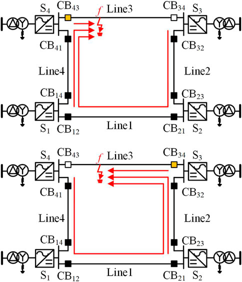
For the Zhangbei 4-terminal grid shown in Figure 1, it is assumed that a positive grounding fault occurs at f on Line3. The fault isolation process of the DC side when circuit breakers CB43 and CB34 fail to operate is shown in Figure 1.
Figure 1 shows that when CB43 or CB34 fails to operate, although one side of the fault line is successfully cut off, each inverter will continue to inject fault current into the fault point through the failed circuit breaker.
2.1 Characteristics of fault current
Assuming that a positive grounding fault occurs at the midpoint of Line3 at 2s, the fault current characteristics of CB43 at the transmitting end and CB34 at the receiving end are analyzed.
CB43 and CB34 both receive trip signals at 1 ms after the fault. Considering that the circuit breaker breaking delay tcb is 3 ms, if the circuit breaker operates normally, the current breaking process should start at 4 ms after the fault.
Converter station S4 is the rectifier station and converter station S3 is the inverter station. During the normal operation of the system, station S4 transmits current to station S3. The comparison of I_CB43 when CB43 operates correctly or fails to operate is shown in Figure 2A. The comparison of I_CB34 when CB34 operates correctly or fails to operate is shown in Figure 2B.
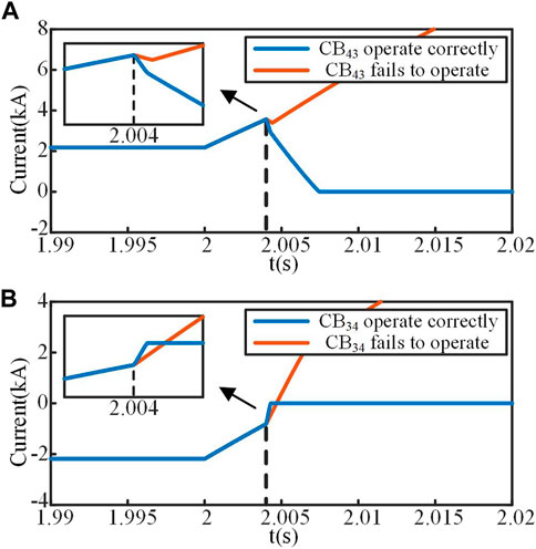
FIGURE 2. Comparison of fault currents when the circuit breaker operates correctly or fails to operate. (A) Fault current of the transmitting terminal I_CB43. (B) Fault current of the receiving terminal I_CB34.
It can be seen from Figure 2A that when CB43 operates correctly, I_CB43 begins to drop at 2.004 s and finally reaches zero, and the fault line is successfully removed. When CB43 fails to operate, I_CB43 begins to experience a short decline at 2.004 s due to the disconnection of CB34 on the opposite side of the fault line. Although the opposite circuit breaker CB34 acted correctly to remove the fault line on one side of the fault point, the fault discharge circuit on the other side of the fault point is not removed, so I_CB43 rises again after a short fall.
It can be seen from Figure 2B that when CB34 operates correctly, the rise speed of I_CB34 increases at 2.004 s and finally reaches zero, and the fault line is successfully removed. When CB34 fails to operate, I_CB34 begins to experience acceleration at 2.004 s due to the disconnection of CB43 on the opposite side of the fault line. Although the opposite circuit breaker CB43 acted correctly to remove the fault line on one side of the fault point, the fault discharge circuit on the other side of the fault point is not removed, so I_CB34 continues to rise after rising to zero.
2.2 Influence of the opposite circuit breaker disconnection on the fault current at the transmitting end
The comparison between I_CB43 and I_CB34 when circuit breaker CB43 operates correctly or fails to operate is shown in Figure 3. Figure 3A shows that after the fault occurs, CB34 and CB43 operate correctly. At 2.004 s, CB34 and CB43 begin to operate simultaneously. At time t1, CB34 is cut off, and I_CB34 drops to zero, and the rate of change of I_ CB43 changes. At time t2, CB43 is cut off, I_CB43 drops to zero and the fault line is completely cut off.
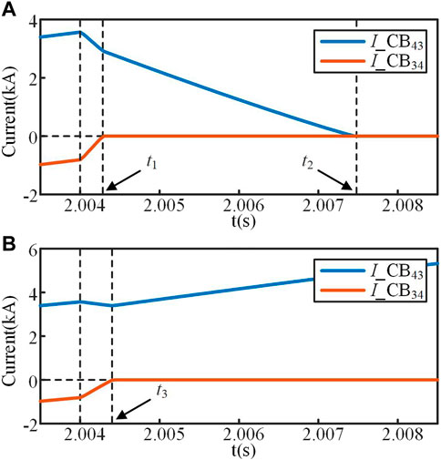
FIGURE 3. Comparison of the fault currents of the failed circuit breaker at the transmitting end and the opposite circuit breaker. (A) Circuit breakers operate correctly. (B) CB43 fails to operate.
Figure 3B shows that after the fault occurs, CB43 fails to operate, while CB34 operates correctly. At 2.004 s, CB34 begins to operate, and owing to its disconnection, I_ CB43 begins to experience a brief decline process. At time t3, CB34 is cut off, and I_ CB34 drops to zero. As the fault discharge circuit through the failed circuit breaker CB43 has not been cut off, the inverters in the network will continue to inject current into the fault point. Therefore, I_ CB43 rises again after a brief decline process. According to the above analysis, when the circuit breaker at the transmitting end fails to operate, owing to the influence of the opposite circuit breaker disconnection, the rising speed of the fault current flowing through the circuit breaker at the transmitting end slows and may even decrease for a short time.
2.3 Influence of the opposite circuit breaker disconnection on the fault current at the receiving end
The comparison between I_CB43 and I_CB34 when circuit breaker CB34 operates correctly or fails to operate is shown in Figure 4. Figure 4A shows that after the fault occurs, CB34 and CB43 operate correctly. At 2.004 s, CB34 and CB43 begin to operate simultaneously. At time t1, CB34 is cut off, I_CB34 drops to zero, and the rate of change of I_CB43 changes. At time t2, CB43 is cut off, I_CB43 drops to zero and the fault line is completely cut off.
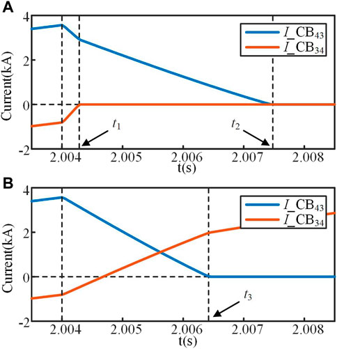
FIGURE 4. Comparison of the fault currents of the failed circuit breaker at the receiving end and the opposite circuit breaker. (A) Circuit breakers operate correctly. (B) CB34 fails to operate.
Figure 4B shows that after the fault occurs, CB34 fails to operate, while CB43 operates correctly. At 2.004 s, CB43 begins to operate, and owing to its disconnection, I_CB34 begins to experience an accelerated rising process and cross zero. At time t3, CB43 is cut off and I_CB43 drops to zero. As the fault discharge circuit through the failed circuit breaker CB34 has not been cut off, the inverters in the network will continue to inject current into the fault point. Therefore, the rate of change of I_CB34 resumes and continues to rise.
According to the above analysis, when the circuit breaker at the receiving end fails to operate, owing to the influence of the opposite circuit breaker disconnection, the rising speed of the fault current flowing through the circuit breaker at the receiving end increases.
2.4 Analysis of the influence of circuit breaker disconnection
For the Zhangbei 4-terminal grid shown in Figure 1, it is assumed that a fault occurs at f on Line3; the fault current path and composition are shown in Figure 5. Converter station S4 is a rectifier station that is at the transmitting end, and converter station S3 is an inverter station that is at the receiving end. Only Line3 and its converter stations on both sides are considered here, while other lines and converter stations are omitted in the figure.
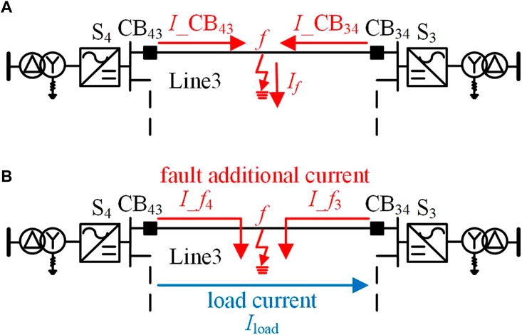
FIGURE 5. Fault current path and composition on the fault line. (A) Fault current path. (B) Fault current composition.
Figure 5 shows that the fault currents I_CB43 and I_CB34 are composed of load current Iload, fault additional current I_ f4, and fault additional current I_ f3:
According to 1), the fault current at transmitting end I_CB43 is composed of load current Iload and fault additional current at transmitting end I_ f4. When the circuit breaker at receiving end CB34 begins to operate, the load current Iload passing through the fault line decreases accordingly. The total current at transmitting end I_CB43 has the same direction as the load current Iload, so the rising speed of I_CB43 decreases.
According to 1), the fault current at receiving end I_CB34 is composed of load current Iload and fault additional current at receiving end I_ f3. When the circuit breaker at transmitting end CB43 begins to operate, the load current Iload passing through the fault line decreases accordingly. The total current at receiving end I_CB34 is in the opposite direction to the load current Iload, so the rising speed of I_CB34 increases.
The disconnection process of the opposite circuit breaker will lead to a decrease in the rise rate of the fault current at the transmitting end. The disconnection process of the opposite circuit breaker will lead to an increase in the rising rate of the fault current at the receiving end.
3 DCCB failure protection
In traditional AC circuit breaker failure protection, the discriminant element determines whether the fault is eliminated by detecting whether there is still current in the system after the protection action, and then, together with the starting element that reflects the protection action, forms the operating condition of AC circuit breaker failure protection. In MMC-HVDC grids, the development of the fault is very fast, and the traditional “present current” discrimination method used in AC systems has a long discrimination process, which cannot meet the rapid demand of circuit breaker failure protection action in the MMC-HVDC grid.
According to the analysis of fault current characteristics after the failure of DCCB in Section 2.1, in MMC-HVDC grids, when a circuit breaker fails to operate, the fault current flowing through the failed circuit breaker will continue to rise after the cut-off time. Based on the above characteristics, an “increase current” discrimination method for DCCBs is studied, which identifies whether the fault has been eliminated by the changing trend of the fault current flowing through the circuit breaker, and then the failure protection of DCCB is constructed. Compared with the traditional “present current” judgment method, the “increase current” judgment method can rapidly determine the failure state of circuit breakers in MMC-HVDC grids, which is conducive to the fast action of circuit breaker failure protection.
3.1 Discrimination method of circuit breaker failure
The hybrid DCCB has a circuit breaker opening delay when cutting off the current When the circuit breaker opening delay is set to its maximum value, the circuit breaker is disconnected at the latest possible moment. For the circuit breaker failure state discrimination process, to ensure that the fault current has begun to decrease at the cut-off time, the cut-off time in this chapter refers to the situation when the breaker’s opening delay reaches the maximum value The first “increase current” discrimination is carried out at the cut-off time.
In view of the different influences caused by the disconnection process of circuit breakers at the transmitting end and receiving end, the circuit breaker failure protection is set to two different modes: the transmitting end and the receiving end. In practical engineering, the mode is switched according to the running state to ensure the correct action of circuit breaker failure protection.
3.1.1 Discrimination of circuit breaker failure at the transmitting end
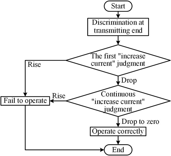
For circuit breakers at the transmitting end, when a fault occurs on the line where the circuit breaker is located, the direction of the fault current change is the same as that of the current in normal operation. Fault current is always in the rising stage from the time the circuit breaker receives the tripping command to the start of the cut-off, so the fault current is always positive before the cut-off time. When the circuit breaker operates correctly or the opposite circuit breaker begins to operate, the rising speed of the fault current will decrease. Therefore, after the cut-off time, once the current flowing through the circuit breaker rises, it can be determined that the circuit breaker fails to operate.
The first “increase current” judgment is made at the cut-off time. If the fault current rises, it is determined that the circuit breaker fails to operate. If the fault current drops, it cannot be determined whether the circuit breaker operates correctly. It is necessary to continuously conduct “increase current” judgment considering the influence of opposite circuit breaker disconnection and the blocking of converter stations. Before the fault current drops to zero, once the trend of the fault current changes and starts to rise, it is determined that the circuit breaker fails to operate. If the fault current continues to decrease and eventually reaches zero, it is determined that the circuit breaker operates correctly. The failure discrimination flow chart of the circuit breaker at the transmitting end is shown in Figure 6.
3.1.2 Discrimination of circuit breaker failure at the receiving end
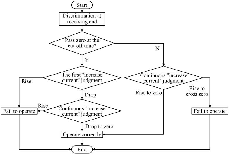
For circuit breakers at the receiving end, when a fault occurs on the line where the circuit breaker is located, the direction of the fault current change is opposite to the direction of the current in normal operation, so the fault current may cross zero. According to the zero-crossing situation of the fault current at the cut-off time, the failure discrimination of circuit breakers at the receiving end can be divided into the following two cases:
When the fault current at the receiving end has passed zero at the cut-off time, the failure discrimination process of circuit breakers at the receiving end is the same as that at the transmitting end.
When the fault current at the receiving end remains negative and does not cross zero before the cut-off time, the direction of the fault current change is positive. When the circuit breaker operates correctly or the opposite circuit breaker begins to operate, the rising speed of the fault current will increase. Therefore, the fault current must be a rising trend during the first “increase current” judgment. If the fault current continues to rise to zero and no longer increases, it is determined that the circuit breaker operates correctly. If the fault current continues to rise above zero and continues to rise, it is determined that the circuit breaker fails to operate. The failure discrimination flow chart of the circuit breaker at the receiving end is shown in Figure 7.
3.2 Failure criterion of the DCCB
In the process of circuit breaker failure discrimination, it is necessary to distinguish the trend of fault current change. Considering the influence of measurement errors, the following “increase current” judgment criteria are proposed for the DCCB.
where icb is the fault current flowing through the circuit breaker and tinc is the time when the change rate of the fault current continues to be greater than or less than 0. tpb is the set time of discrimination, which depends on the accuracy of current detection and was set to 0.2 ms in this study. To ensure the reliability of the criterion, the fault current can only be determined to rise or fall when tinc reaches the set time of discrimination.
In the process of circuit breaker failure discrimination, it is necessary to distinguish the return to zero state of the fault current. Considering the influence of measurement errors, the following “return to zero” judgment criteria are proposed for the DCCB.
where icb is the fault current flowing through the circuit breaker. iset is the set value of zero discrimination, trz is the time when the absolute value of the fault current continues to be less than the set value of zero discrimination, and tpb is the set time of discrimination. To ensure the reliability of the criterion, the fault current can only be determined to return to zero when tinc reaches the set time of discrimination.
3.3 Analysis of discrimination of DCCB failure protection
For circuit breakers at the transmitting end, according to the completion time of the circuit breaker failure discrimination, the discrimination results can be divided into three cases: 1) The fault current rises when the first judgment is made, indicating that the circuit breaker fails to operate. 2) The fault current first drops and then rises, indicating that the circuit breaker fails to operate. 3) The fault current drops to zero, indicating that the circuit breaker operates correctly.
For circuit breakers at the receiving end, according to the zero crossing of the fault current at the cut-off time and the completion time of the circuit breaker failure discrimination, the discrimination results can be divided into four cases: 1) the fault current has passed zero at the cut-off time, and then the fault current rises, indicating that the circuit breaker fails to operate; 2) the fault current has passed zero at the cut-off time, and then the fault current drops to zero, indicating that the circuit breaker operates correctly; 3) the fault current has not passed zero at the cut-off time, and then the fault current rises to cross zero, indicating that the circuit breaker fails to operate; and 4) the fault current has not passed zero at the cut-off time, and then the fault current rises to zero and will no longer rise, indicating that the circuit breaker operates correctly.
3.4 Secondary accelerated fault isolation scheme
When a fault occurs in the MMC-HVDC grid and the circuit breaker fails to operate, it can lead to rapid isolation failure. In this case, targeted isolation measures need to be taken to minimize the fault isolation scope and complete fault isolation as soon as possible.
When the failure of DCCB is caused by non-serious faults, such as internal control or driving mechanism errors, sending a tripping signal again can make the failed circuit breaker trip successfully. Therefore, when the circuit breaker failure protection acts, the first step is to send a re-tripping command to the failed circuit breaker. In addition, during the circuit breaker failure discrimination, the converter connected to the circuit breaker may be blocked. After the converter is blocked, the non-fault line on the other side cannot exchange energy normally. Therefore, when the converter is blocked, a trip signal should be immediately sent to the circuit breaker on the non-fault line on the other side of the converter station to accelerate the removal of the fault line.
Based on the above analysis, a secondary accelerated fault isolation scheme is proposed, which includes failed breaker re-tripping, adjacent DCCB action, the blocking of the converter station, and AC circuit breaker action, so as to achieve the secondary accelerated fault isolation after the failure of the DCCB in the MMC-HVDC grids. Below is a detailed explanation of two aspects: DC side fault isolation and AC side fault isolation.
For DC side fault isolation: after the circuit breaker failure protection action, if the failed circuit breaker successfully re-trips before the converter is blocked, the adjacent DCCB does not need to operate and other parts of the system can continue to operate except for the successful removal of the fault line. If the converter is blocked before the failed circuit breaker successfully re-trips, a trip signal should be immediately sent to the circuit breaker on the non-fault line on the other side of the converter station. If the circuit breaker fails to re-trip and the converter is not blocked, the converter should be blocked immediately, and a trip signal should be sent to the circuit breaker on the non-fault line on the other side of the converter station. After the circuit breaker failure protection action, it can quickly send a trip signal to the adjacent circuit breaker to achieve secondary accelerated isolation of DC faults.
For AC side fault isolation: after the circuit breaker failure protection action, regardless of whether the converter connected to the failed circuit breaker is blocked or not, as long as the failed circuit breaker does not trip successfully, the AC side can continuously inject fault current into the fault point through the failed circuit breaker. At this point, it is necessary to disconnect the AC circuit breaker connected to the converter station to achieve the removal of the fault path. However, the operation time and re-input time of the AC circuit breaker are relatively long. Considering the requirements of rapid DC fault isolation and rapid recovery after fault isolation, the tripping of the AC circuit breaker can be avoided as much as possible by re-tripping the failed circuit breaker. If the failed circuit breaker re-trips successfully, there is no need to cut off the AC circuit breaker connected to the converter station where the failed circuit breaker is located. If the failed circuit breaker fails to re-trip, a trip signal should be immediately sent to the AC circuit breaker connected to the converter station where the failed circuit breaker is located to remove the fault path between the AC side and the fault point.
4 Simulation verification
For the Zhangbei 4-terminal grid shown in Figure 1, the effectiveness of the circuit breaker failure state discrimination method and secondary accelerated fault isolation scheme is verified by a simulation on PSCAD.
The maximum breaking delay tcb of the circuit breaker is set as 3 ms, and the sampling frequency is 40 kHz. To avoid data errors caused by interference, the set time for “increase current” discrimination tpb is set as 0.2 ms, and the set value of zero discrimination iset is set as 0.01 kA.
4.1 Verification of circuit breaker failure discrimination
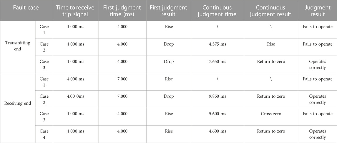
In view of the possible discriminant process of circuit breaker failure, the failure state of the circuit breaker at the transmitting end and the circuit breaker at the receiving end are verified. The specific circuit breaker failure discrimination process is shown in Table 1.
4.1.1 Verification of failure discrimination for circuit breakers at the transmitting end
Assume that a positive grounding fault occurs at the midpoint of Line3 at 2 s. For circuit breakers at the transmitting end, according to the time when the circuit breakers receive trip signals, the change of fault current can be divided into three cases.
Case 1: CB43 fails to operate, and the fault current rises during the first discrimination.Assuming that CB43 at the transmitting end receives a trip signal at 2.001 s and CB34 at the receiving end receives a trip signal at 2.002 s, the fault current I_CB43 is shown in Figure 8A. The circuit breaker failure protection starts to conduct failure discrimination at 2.004 s. After 0.2 ms, the first “increase current” judgment is completed and I_CB43 is detected as a rising trend, indicating that CB43 fails to operate. Therefore, the circuit breaker failure protection will act immediately.
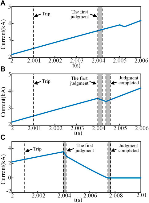
FIGURE 8. Failure discrimination for circuit breakers at the transmitting end. (A) Case 1. (B) Case 2. (C) Case 3.
Case 2: CB43 fails to operate, and the fault current first drops and then rises.Assuming that both CB43 at the transmitting end and CB34 at the receiving end receive trip signals at 2.001 s, the fault current I_CB43 is shown in Figure 8B. The circuit breaker failure protection starts to conduct failure discrimination at 2.004 s. After 0.2 ms, the first “increase current” judgment is completed, and I_CB43 is detected as a dropping trend. At this time, the circuit breaker failure state cannot be determined, and it is necessary to continuously conduct “increase current” judgment. At 4.575 ms after the fault, I_CB43 is detected to be on the rise, and the failure discrimination is completed, indicating that CB43 fails to operate. Therefore, the circuit breaker failure protection will act immediately.
Case 3: CB43 operates correctly, and the fault current drops to zero.Assuming that both CB43 at the transmitting end and CB34 at the receiving end receive trip signals at 2.001 s, the fault current I_CB43 is shown in Figure 8C. The circuit breaker failure protection starts to conduct failure discrimination at 2.004 s. After 0.2 ms, the first “increase current” judgment is completed, and I_CB43 is detected as a dropping trend. At this time, the circuit breaker failure state cannot be determined, and it is necessary to continuously conduct “increase current” judgment. At 7.650 ms after the fault, I_CB43 is detected to be zero and will no longer rise, and the failure discrimination is completed, indicating that CB43 operates correctly. Therefore, the circuit breaker failure protection will no longer act.
4.1.2 Verification of failure discrimination for circuit breakers at the receiving end
For circuit breakers at the receiving end, according to the zero-crossing situation of fault current at the cut-off time and the time when the circuit breakers receive trip signals, the change of fault current can be divided into four cases.
It is assumed that a positive grounding fault occurs at the end of Line3 at 2 s, corresponding to the change of fault current in case 1 and case 2. It is assumed that a positive grounding fault occurs at the midpoint of Line3 at 2 s, corresponding to the changes in fault current in case 3 and case 4.
Case 1: CB34 fails to operate. The fault current has passed zero and rises during the first discrimination.Assuming that CB43 at the transmitting end receives a trip signal at 2.002 s and CB34 at the receiving end receives a trip signal at 2.004 s, the fault current I_CB34 is shown in Figure 9A. The circuit breaker failure protection starts to conduct failure state discrimination at 2.007 s. After 0.2 ms, the first “increase current” judgment is completed and I_CB34 is detected as a rising trend, indicating that CB34 fails to operate. Therefore, the circuit breaker failure protection will act immediately.
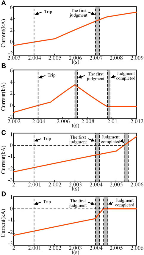
FIGURE 9. Failure discrimination for circuit breakers at the receiving end. (A) Case 1. (B) Case 2. (C) Case 3. (D) Case 4.
Case 2: CB34 operates correctly. The fault current has passed zero and drops to zero.Assuming that CB43 at the transmitting end receives a trip signal at 2.002 s and CB34 at the receiving end receives a trip signal at 2.004 s, the fault current I_CB34 is shown in Figure 9B. The circuit breaker failure protection starts to conduct failure discrimination at 2.007cs. After 0.2cms, the first “increase current” judgment is completed, and I_CB34 is detected as a dropping trend. At this time, the circuit breaker failure state cannot be determined, and it is necessary to continuously conduct “increase current” judgment. At 9.850cms after the fault, I_CB34 is detected to be zero and will no longer rise, and the failure discrimination is completed, indicating that CB34 operates correctly. Therefore, the circuit breaker failure protection will no longer act.
Case 3: CB34 fails to operate. The fault current has not passed zero and rises to cross zero.Assuming that CB43 at the transmitting end receives a trip signal at 2.002 s and CB34 at the receiving end receives a trip signal at 2.001 s, the fault current I_CB34 is shown in Figure 9C. The circuit breaker failure protection starts to conduct failure discrimination at 2.004 s. After 0.2 ms, the first “increase current” judgment is completed, and I_CB34 is detected as a rising trend. At this time, the circuit breaker failure state cannot be determined, and it is necessary to continuously conduct “increase current” judgment. At 5.600 ms after the fault, I_CB34 is detected to cross zero and continue to rise, and the failure discrimination is completed, indicating that CB34 fails to operate. Therefore, the circuit breaker failure protection will act immediately.
Case 4: CB34 operates correctly. The fault current has not passed zero and rises to zero and will no longer rise.
Assuming that CB43 at the transmitting end receives a trip signal at 2.002 s and CB34 at the receiving end receives a trip signal at 2.001 s, the fault current I_CB34 is shown in Figure 9D. The circuit breaker failure protection starts to conduct failure discrimination at 2.004 s. After 0.2 ms, the first “increase current” judgment is completed, and I_CB34 is detected as a rising trend. At this time, the circuit breaker failure state cannot be determined, and it is necessary to continuously conduct “increase current” judgment. At 4.600 ms after the fault, I_CB34 is detected to be zero and will no longer rise, and the failure discrimination is completed, indicating that CB34 operates correctly. Therefore, the circuit breaker failure protection will no longer act.
4.2 Verification of a secondary accelerated fault isolation scheme
Assuming that a fault occurs on Line3 and CB43 fails and refuses to operate, the fault isolation scheme, including the re-tripping of the failed circuit breaker CB43, adjacent DCCB action, the blocking of converter station S4, and AC circuit breaker action, is verified. The fault isolation can be divided into three cases.
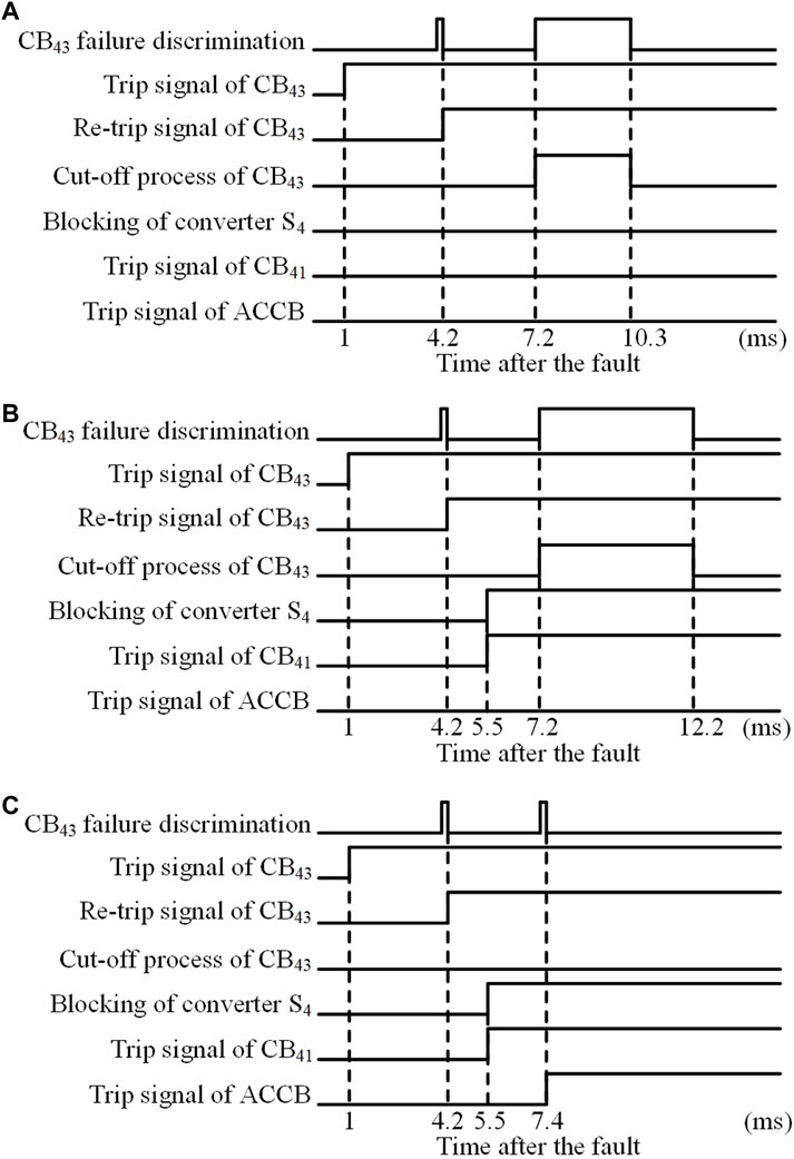
Case 1: the failed circuit breaker re-trips successfully before the converter is blocked.A positive ground fault with a transition resistance of 100 Ω occurs at the midpoint of Line3 at 2s.It is assumed that CB43 receives a trip signal at 1 ms after the fault, and CB43 is judged to fail to operate, and a re-tripping signal is sent at 4.2 ms after the fault. The re-tripping failure discrimination is conducted at 7.2 ms after the fault, and CB43 is judged to re-trip successfully at 10.3 ms after the fault. At this time, the converter station S4 is still not blocked, so the adjacent circuit breaker CB41 and the AC circuit breaker do not need to trip. In this case, the fault isolation process is shown in Figure 10A.
Case 2: the converter has been blocked before the re-tripping failure discrimination is completed, and the failed circuit breaker re-trips successfully.A positive ground fault occurs at the midpoint of Line3 at 2 s.It is assumed that CB43 receives a trip signal at 1 ms after the fault, and CB43 is judged to fail to operate, and a re-tripping signal is sent at 4.2 ms after the fault. The converter station S4 is blocked, and a trip signal is immediately sent to the adjacent circuit breaker CB41 at 5.5 ms after the fault. The re-tripping failure discrimination is conducted at 7.2 ms after the fault, and CB43 is judged to have re-tripped successfully at 12.2 ms after the fault. At this time, the AC circuit breaker does not need to trip. In this case, the fault isolation process is shown in Figure 10B.
Case 3: the converter has been blocked before the re-tripping failure discrimination is completed, and the failed circuit breaker fails to re-trip.A positive ground fault occurs at the midpoint of Line3 at 2 s.It is assumed that CB43 receives a trip signal at 1 ms after the fault, and CB43 is judged to have failed to operate, and a re-tripping signal is sent at 4.2 ms after the fault. The converter station S4 is blocked, and a trip signal is immediately sent to the adjacent circuit breaker CB41 at 5.5 ms after the fault. The re-tripping failure discrimination is conducted at 7.2 ms after the fault, and CB43 is judged to have failed to re-trip at 7.4 ms after the fault. At this time, a trip signal is immediately sent to the AC circuit breaker connected to converter station S4. In this case, the fault isolation process is shown in Figure 10C.
4.3 Verification of the secondary accelerated isolation effect
After the DCCB failure protection action, the accelerated isolation of DC faults is achieved by tripping the adjacent DCCB. Assuming that a positive grounding fault occurs at the midpoint of Line3 at 2 s and CB43 fails to operate, the acceleration isolation effect of DC faults is simulated and analyzed.
When the circuit breaker failure protection is configured in the system, during the circuit breaker failure discrimination, the converter station S4 is blocked, and the circuit breaker failure protection acts immediately at 5.5 ms after the fault. A trip signal is sent to CB41 located on the non-fault line on the other side of the converter station to isolate the fault, and the main protection set in converter station S1 no longer acts.
When the circuit breaker failure protection is not configured in the system, CB41 will no longer operate. The main protection set in converter station S1 predicts the blocking time of the converter station according to the real-time fault current data and selects CB14 as the pre-trip circuit breaker based on the fault current direction criterion. When the protection acts, a tripping signal will be sent to CB14 to remove the fault.
With or without circuit breaker failure protection configured in the system, the comparison of the bridge arm current changes of the converter station S1 is shown in Figure 11. Figure 11A shows that the DC fault is cleared at 8.5 ms after the fault when the failure protection trips CB41. Figure 11B shows that the DC fault is cleared at 12.6 ms after the fault when the main protection of converter station S1 trips CB14. From this, when a fault occurs in the DC grid and the circuit breaker fails to operate, the circuit breaker failure protection action can remove the fault faster, achieving the accelerated isolation of DC faults.
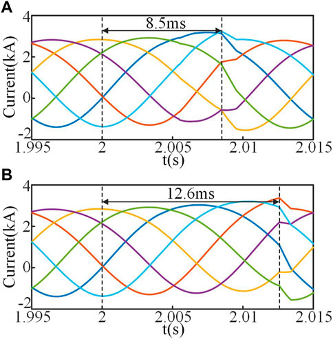
FIGURE 11. Comparison of the bridge arm current changes of S1. (A) The failure protection trips CB41 after the failure of CB43. (B) The main protection of S1 trips CB14 after the failure of CB43.
4.4 Verification of the Re-tripping of the failed circuit breaker
The re-tripping of the failed circuit breaker can effectively avoid the problem of long tripping time caused by isolating faults through the action of AC circuit breakers. It is assumed that when a positive ground fault occurs at the midpoint of Line3 at 2 s and CB43 fails to operate, the re-tripping process of the failed circuit breaker after the failure of the DCCB is verified.
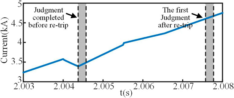
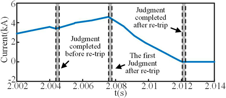
Assuming that both CB43 and CB34 receive trip signals at 2.001 s, the circuit breaker failure protection starts to conduct failure discrimination at 2.004 s. The first “increase current” judgment is completed at 4.200 ms after the fault, but the circuit breaker failure state cannot be determined. At 4.575 ms after the fault, I_CB43 is detected to be on the rise, and the failure discrimination is completed, indicating that CB43 fails to operate. Therefore, the trip signal is immediately sent to CB43 again, and the re-tripping failure discrimination is conducted at 7.575 ms after the fault.
When CB43 fails to re-trip, the fault current I_CB43 is shown in Figure 12. The first judgment after re-tripping is completed at 7.775 ms after the fault, and I_CB34 is detected as a rising trend, indicating that CB43 fails to re-trip. Therefore, a trip signal is immediately sent to the relevant AC circuit breaker.
When CB43 re-trips successfully, the fault current I_CB43 is shown in Figure 13. The first judgment after re-tripping is completed at 7.775 ms after the fault, and I_CB34 is detected as a dropping trend. At this time, the circuit breaker failure state cannot be determined. At 12.250 ms after the fault, I_CB43 is detected to be zero and will no longer rise, and the re-tripping failure discrimination is completed, indicating that CB43 re-trips successfully. Therefore, the AC circuit breaker does not need to trip.
The comparison of AC current flowing into converter station S4 between successful and failed re-tripping of the failed circuit breaker CB43 is shown in Figure 14. Figure 14 shows that when the failed circuit breaker re-trips successfully, there is no need to disconnect the AC circuit breaker to isolate the fault, and the AC fault current injected into the converter station where the failed circuit breaker is located will be cleared faster.
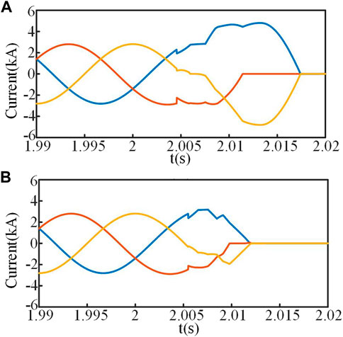
FIGURE 14. Comparison of the AC current changes of S4. (A) The failed circuit breaker CB43 fails to re-trip. (B) The failed circuit breaker CB43 re-trips successfully.
5 Conclusion
This paper proposes a secondary accelerated fault isolation scheme for MMC-HVDC grids after rapid fault isolation failure. Considering the influence caused by the disconnection process of the opposite circuit breaker, the fault current characteristics after the failure of the DCCB are analyzed. The method of circuit breaker failure discrimination using “increase current” judgment is studied. By analyzing the logical relationship among failed breaker re-tripping, adjacent DCCB action, the blocking of the converter station, and AC circuit breaker action, a secondary accelerated fault isolation scheme is proposed to minimize the fault isolation area. The main conclusions and innovations are as follows:
1) The fault current characteristics after the failure of the DCCB are analyzed. In MMC-HVDC grids, when a circuit breaker fails to operate, the overall trend of the fault current flowing through the failed circuit breaker continues to rise when the influence of the opposite circuit breaker disconnection is not considered. The disconnection process of the opposite circuit breaker will lead to a decrease in the rise rate of the fault current at the transmitting end, and will lead to an increase in the rise rate of the fault current at receiving end.
2) A method of circuit breaker failure discrimination using “increase current” judgement is proposed. The method fully considers the influence of the opposite circuit breaker disconnection. Compared with the traditional “present current” judgement method, the “increase current” judgement method can rapidly determine the failure state of the DCCB, which is conducive to the fast action of circuit breaker failure protection.
3) A secondary accelerated fault isolation scheme after rapid isolation failure in the MMC-HVDC grid is proposed. The scheme achieves the accelerated isolation of DC faults by tripping the adjacent DCCB, which is beneficial for the safe operation of the non-fault parts of the system. Additionally, by re-tripping the failed circuit breaker, the fault point is successfully isolated from the AC side line, which can effectively avoid the trip of the AC circuit breaker.
Data availability statement
The original contributions presented in the study are included in the article/supplementary material, further inquiries can be directed to the corresponding author.
Author contributions
AL: Software, methodology, data Curation, writing—original draft; BoL: Conceptualization, software, investigation; WW: Supervision, Writing—review and editing, visualization; BiL and XC: Supervision; writing—review and editing. All authors contributed to the article and approved the submitted version.
Funding
This work was supported by the Joint Funds of the National Natural Science Foundation of China (U2166205).
Conflict of interest
The authors declare that the research was conducted in the absence of any commercial or financial relationships that could be construed as a potential conflict of interest.
Publisher’s note
All claims expressed in this article are solely those of the authors and do not necessarily represent those of their affiliated organizations, or those of the publisher, the editors and the reviewers. Any product that may be evaluated in this article, or claim that may be made by its manufacturer, is not guaranteed or endorsed by the publisher.
References
Azad, S. P., Leterme, W., and Hertem, D. V. (2016). Fast breaker failure backup protection for HVDC grids. Electr. Power Syst. Res. 138, 99–105. doi:10.1016/j.epsr.2016.03.003
Ding, S. (2006). Analysis on some problems of breaker failure protection. Automation Electr. Power Syst. 30 (3), 89–91. doi:10.3321/j.issn:1000-1026.2006.03.017
Franck, C. M. (2011). HVDC circuit breakers: A review identifying future research needs. IEEE Trans. Power Deliv. 26 (2), 998–1007. doi:10.1109/TPWRD.2010.2095889
He, C., and Li, X. (2010). Analysis of some problems on 220 kV circuit breaker failure protection of main transformer high-voltage side. Power Syst. Prot. Control 38 (1), 102–106. doi:10.3969/j.issn.1674-3415.2010.01.024
Khosravi, N., Abdolvand, A., Oubelaid, A., Khan, Y., Bajaj, M., and Govender, S. (2021). Improvement of power quality parameters using modulated-unified power quality conditioner and switched-inductor boost converter by the optimization techniques for a hybrid AC/DC microgrid. Sci. Rep. 12 (1), 21675. doi:10.1038/s41598-022-26001-8
Oubelaid, A., Albalawi, F., Rekioua, T., Ghoneim, S., Taib, N., and Abdelwahab, S. (2022a). Intelligent torque allocation based coordinated switching strategy for comfort enhancement of hybrid electric vehicles. IEEE ACCESS 10, 58097–58115. doi:10.1109/ACCESS.2022.3178956
Oubelaid, A., Taib, N., Nikolovski, S., Alharbi, T., Rekioua, T., Flah, A., et al. (2022b). Intelligent speed control and performance investigation of a vector controlled electric vehicle considering driving cycles. Electronics 11 (13), 1925. doi:10.3390/electronics11131925
Perez-Molina, M., Larruskain, D., Eguia, P., and Abarrategi, O. (2021). Circuit breaker failure protection strategy for HVDC grids. Energies 14 (14), 4326. doi:10.3390/en14144326
Qin, D., Chen, Y., Zhang, Z., and Enslin, J. (2022). “A hierarchical microgrid protection scheme using hybrid breakers,” in IEEE International Symposium on Power Electronics for Distributed Generation Systems, Chicago, IL, USA. 28 June 2021 - 01 July 2021 (IEEE), doi:10.1109/PEDG51384.2021.9494192
Song, Y. (2008). Research on several questions of line circuit breaker failure protection. Power Syst. Prot. Control 36 (23), 88–91. doi:10.3969/j.issn.1674-3415.2008.23.021
Wang, M., Zaja, M., Beerten, J., Jovcic, D., and Van, H. D. (2021). Backup protection algorithm for failures in modular DC circuit breakers. IEEE Trans. Power Deliv. 36 (6), 3580–3589. doi:10.1109/TPWRD.2020.3045262
Xu, Z., Xiao, H., and Xu, Y. (2018). Study on basic principle and its realization methods for DC circuit breakers. High. Volt. Eng. 44 (2), 347–357. doi:10.13336/j.1003-6520.hve.20180131002
Zhang, H., and Chang, F. (2003). Breaker failure protection of high voltage power system. Electr. Power Autom. Equip. 23 (5), 79–81. doi:10.3969/j.issn.1006-6047.2003.05.023
Keywords: VSC-HVDC grids, direct current circuit breaker, circuit breaker failure protection, failure discrimination, secondary accelerated fault isolation
Citation: Li A, Li B, Wen W, Li B and Chen X (2023) Research on circuit breaker failure protection and the secondary accelerated fault isolation scheme of VSC-HVDC grids. Front. Energy Res. 11:1211269. doi: 10.3389/fenrg.2023.1211269
Received: 24 April 2023; Accepted: 31 May 2023;
Published: 14 June 2023.
Edited by:
Srete Nikolovski, Josip Juraj Strossmayer University of Osijek, CroatiaReviewed by:
Dehao Qin, Clemson University, United StatesAdel Oubelaid, Université de Bejaia, Algeria
Copyright © 2023 Li, Li, Wen, Li and Chen. This is an open-access article distributed under the terms of the Creative Commons Attribution License (CC BY). The use, distribution or reproduction in other forums is permitted, provided the original author(s) and the copyright owner(s) are credited and that the original publication in this journal is cited, in accordance with accepted academic practice. No use, distribution or reproduction is permitted which does not comply with these terms.
*Correspondence: Weijie Wen, d2VpamllLndlbkB0anUuZWR1LmNu
 Andi Li
 Botong Li
 Weijie Wen
 Bin Li
 Xiaolong Chen