 Qianjin Zhang
 Qi Hu
Qi Hu- School of Electrical and Information Engineering, Anhui University of Technology, Ma’anshan, China
The voltage and frequency control of photovoltaic (PV) systems are influenced by coupled nonlinear factors. It has been discovered that frequency control stability is threatened by voltage regulation methods in PV systems. However, the frequency instability caused by voltage regulation methods has not been fully investigated. This paper investigates the voltage and frequency stability problems in PV systems connected with weak power grids. The voltage problems caused by grid impedance, comprising inverter AC voltage and DC voltage, are first analyzed. Then, methods for improving voltage stability, such as reactive power compensation, and the benefits and drawbacks of various compensation methods are investigated. Finally, the effect of reactive power compensation on frequency control stability is investigated and resolved. Simulations and experiments are used to validate the theory’s correctness.
1 Introduction
Recent years have seen an apparent rise in the integration of renewable power generation, such as wind and solar, into the electrical grid (Zhang et al., 2021). The traditional power system has been changed and influenced by power electronic equipment. The stability problems are preventing a greater utilization of renewable energy. In terms of PV systems, due to installation space restrictions, large PV stations are typically placed in rural locations where power grid strength is weak, and large disturbances are common. System operation is in danger due to the effect of grid impedance and system nonlinear couplings on inverter control (Liu et al., 2022a; Hafiullah et al., 2022; Wang et al., 2017a; Zhou et al., 2022).
Inverter control stability and system voltage stability are the key topics of research on PV system stability (Zheng et al., 2018; Wei et al., 2020; Liu et al., 2022b). Typical control loops like current, frequency, and voltage control are referred to as control stability. The initial designs of these control loops typically meet the stability criteria, but when coupled to one another and to a weak power grid, the interactions between various control loops in and between different devices lead to system instability (Sun, 2011). A PV system’s voltage and frequency are generally managed by a voltage control loop and a phase-locked loop (PLL). Methods for regulating system voltage, such as power optimization control and reactive power compensation, will interact with inverter control, influencing control stability. It has been reported that series capacitor compensation causes sub-synchronization resonance in wind farms. The interactions of sub-synchronous control between wind turbines and series capacitors have been discovered (Wang et al., 2018). However, the instability is due to the unique circuit structure of doubly fed converters, which is not common in other types of converters (Huang et al., 2016; Zhang et al., 2020). For the stability issues in PV systems, Yang et al. (2019) analyzed the impact of parallel compensation on the control stability of inverters and discovered that parallel compensation decreases the phase margin of inverter current control. The lead compensation was then suggested as a solution to the issue. However, only the stability of the current control was taken into account. There has not been any discussion of the impact on system frequency control.
The frequency stability in the inverter system is generally analyzed based on a PLL (Wang et al., 2017b; Du et al., 2020; Sonawane and Umarikar, 2022). It has been proved that factors such as PI controller parameters, grid impedance, inverter current, and power factor angle significantly affect the stability of the PLL. Different stability improvement methods have been deployed, including increasing system damping, changing control parameters and structure, and intelligent optimization (Lasseter et al., 2020; He et al., 2022; Qi et al., 2022).
However, weak power grids are the focus of the majority of the work. The impact of reactive power compensation has not been taken into account. Zhang et al. (2022) explored the frequency stability problems caused by series capacitors but did not address the influence of parallel compensation. To the best of the authors’ knowledge, no comprehensive analysis of the impact of voltage regulation approaches on frequency control stability has been provided. How reactive power compensation affects frequency control stability and how to deal with the instability issue must be known.
This paper investigates the voltage and frequency instability in large PV systems. The interaction between reactive power compensation and inverter control is investigated. The main contributions of this article are as follows:
• The restriction of parallel compensation is revealed.
• The influence of voltage regulation on frequency control stability is comprehensively analyzed.
• Methods to solve the frequency instability caused by reactive power compensation are proposed, which have high robustness and depend little on specific system models.
The following contents are organized as follows: Section 2 illustrates the voltage instability and regulation methods in PV systems. Section 3 investigates the frequency instability caused by voltage regulation. Section 4 puts forwards the stability improvement methods. Section 5 presents the simulation and experimental results and is followed by the conclusion in Section 6.
2 Voltage instability and regulation methods
The DC bus and the AC bus are the two power buses for a typical grid-connected PV system. The voltages on these two buses are kept constant to meet the needs of the system’s normal operation and the supply of loads (Zhou et al., 2015; Reshikeshan et al., 2021). However, due to the existence of grid impedance in weak power grids, system voltage is determined by voltage control techniques and inverter control. Energy storage and reactive power compensation, in general, are required to adjust system voltage (Liu et al., 2015; Ai et al., 2021). Energy storage devices only operate on active power and are typically installed on DC buses to regulate DC voltage. The reactive power devices, on the other hand, operate on AC buses and have the ability to modify DC and AC voltage. This section analyzes the voltage problems and the voltage regulation methods in PV systems. The restriction of parallel compensation is revealed.
2.1 Voltage problems in PV systems
For the latching current limiter (LCL)-type grid-connected PV inverters, the inverter current (Ipv) is controlled in an αβ frame, and the active current reference (Irefd) is generated by DC voltage (Vdc) control. The reactive power reference current (Irefq) is set to zero in the unit power factor control mode. In the time scale of current control, the dynamic of DC voltage control can be neglected. The system model focusing on the grid side can be deduced, as in Figure 1, where Iref, Vpv, Vg, Zg, and n are, respectively, inverter current reference, inverter voltage, grid voltage, grid impedance, and inverter parallel number. Ti and Ypv are derived as follows:
where L1, L2, and C are the inductors and capacitor of the LCL filter, Kpwm is the inverter gain that equals half of the DC voltage, kc is the active damping coefficient, and Gc represents the PR controller. The current and voltage phasor diagram is shown in Figure 2. According to the triangle rules, it can be derived that
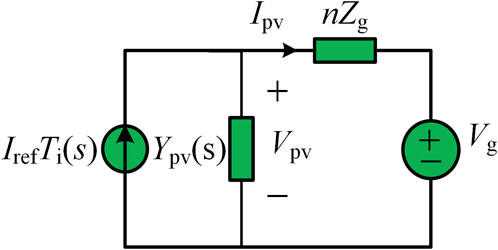
FIGURE 1. Equivalent model of the grid-connected inverter system.
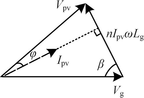
FIGURE 2. Phasors diagram of voltages and currents on the inverter side.
The inverter voltage is deduced as follows:
It can be seen that inverter voltage is affected by many factors, such as the inverter parallel number (n), inverter frequency (ω), inverter current (Ipv), power factor angle (φ), and grid impedance (Lg). Figure 3 shows the voltage curves with different inverter currents and power factors. The voltage decreases with the increase of inverter current for a small power factor angle. The voltage increases first and then decreases for a large power factor angle. Inverter voltage has the risk of exceeding the upper and lower stability limit.
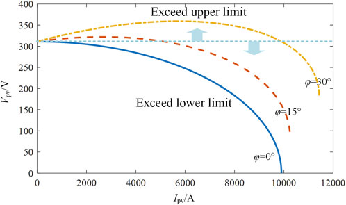
FIGURE 3. Relationships of inverter output voltage and current under different power factors.
As discussed previously, inverter voltage is affected by its output current, so the relationship between output power and output current is nonlinear. The inverter output power can be calculated by
Figure 4 depicts the power curves. It is obvious that there are maximum points for the power curves. Inverter output power can be increased before the maximum points by increasing the current, but once the maximum value is reached, increasing the current causes the output power to decrease. These nonlinear relationships impact system power flow and threaten the stability of inverter control. The output current of PV inverters is typically increased in order to increase the output power. The inverter current is controlled to rise when a large amount of power enters the DC bus. When input power exceeds the maximum point and increasing current fails to increase output power, the unbalanced power will be generated on the DC bus. The unbalanced power increases the DC voltage and leads to the loss of the equilibrium point of DC voltage control. The instability of DC voltage control is induced, which will further cause system oscillation.
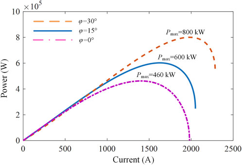
FIGURE 4. Inverter output power under different power factors.
2.2 Reactive power compensation for PV voltage regulation
The aforementioned analysis indicates that the grid impedance is the main factor leading to AC and DC voltage instability. The voltage problem can be resolved as long as the grid impedance’s impact on the inverter output voltage is eliminated. This can be realized by reactive power compensation, which is widely known as an effective way to solve voltage problems. Reactive power compensation includes parallel compensation and series compensation (Sarkar et al., 2018). Parallel compensation is commonly installed inside large PV stations, such as a static synchronous compensator (STATCOM), a static var compensator (SVC), and parallel capacitors (Lee and Yang, 1998).
According to Figure 5, parallel compensation alters the power angle (δ) by injecting reactive current into the system to stabilize inverter voltage, where Ic is reactive current, Ii is inverter current, and Il is grid-connected current. It can be seen that the phase angle between the grid-connected current and inverter voltage is changed by the reactive current. When this angle equals the angle between the grid-connected current and the grid voltage, inverter voltage equals grid voltage. Meanwhile, half of the reactive power for the grid inductor is supplied by PV stations and power grids, respectively.
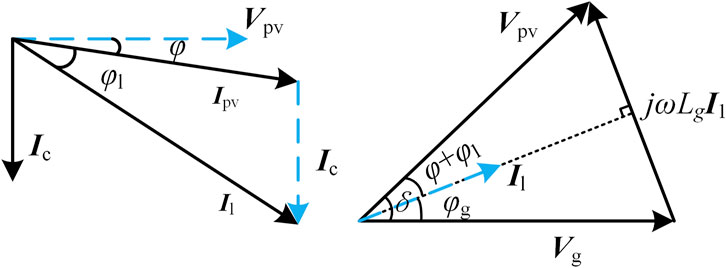
FIGURE 5. Voltage and current phasors of the PV system with parallel compensation.
Generally speaking, parallel compensation can maintain system voltage within the necessary stable range. However, due to the large impedance in an ultra-weak power grid, parallel compensation is probably unable to effectively support the voltage. Taking the unit power factor system as an example, the triangular relationship formed by the AC side voltages is shown in Figure 6, where three cases of parallel compensation are given. It shows that inverter voltage changes with reactive power compensation, but no matter how much compensation is applied, we can always draw a red dashed line perpendicular to the inverter voltage, whose length is always less than the grid voltage. The length of the red dashed line is calculated as follows:
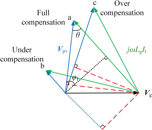
FIGURE 6. Triangle relationships of voltages for a system with different parallel compensations.
Thus, the necessary condition of parallel compensation can be deduced as follows:
The system becomes unstable when (5) is not satisfied under the influence of large grid impedance and/or large inverter current.
Series compensation can compensate for the drawbacks of parallel compensation and is generally deployed on high-voltage transmission lines. Series capacitors are the widely used series compensation devices in PV systems, which can effectively improve inverter voltage by reducing grid impedance, as shown in Figure 7. When the grid inductor is fully compensated, inverter voltage equals grid voltage.
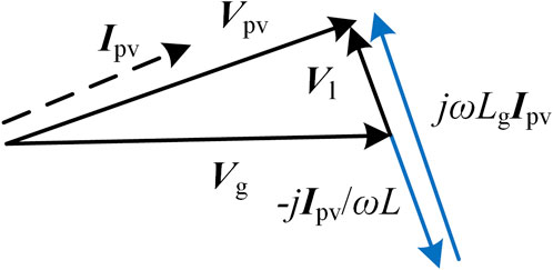
FIGURE 7. Triangle relationships of voltages of a system with series compensation.
3 Frequency control instability
Reactive power compensation is an effective way of ensuring the voltage stability of the PV system and improving system power quality and reliability. However, reactive power compensation is coupled to the inverters’ control by working on inverter voltage (Sridhar et al., 2016; Sudharshan et al., 2022). When the power grid is extremely weak, and the required reactive power compensation is large, reactive power compensation can easily lead to system frequency control instability.
The traditional frequency control part in inverters is a PLL. The input signal of a PLL is inverter voltage. For a weak power grid, the stability of the PLL is affected by grid voltage, grid impedance, grid current, reactive power compensation, etc. By the superposition principle, inverter voltage can be derived as follows:
where Tvs and Tis are, respectively, the transfer function from Vg and Ipvref to Vpv, and
In (8), Zsg(s) is the equivalent grid impedance and
where Cs and Cp are, respectively, the series and parallel compensation capacitors.
For simplification, (7) can be expressed in its exponential form:
The component Vpv in the q axis can be obtained from (10) after the dq transformation as follows:
where || represents amplitude operation, θg and θ are, respectively, the phases of grid voltage and the phase detected by the PLL, and ω0 and ω are, respectively, the frequency of the grid and the PLL. The PV system frequency is determined by ω.
The equivalent control diagram of the PLL is shown in Figure 8. Compared with the ideal condition without grid impedance, the existence of grid impedance and reactive power compensation has introduced a current effect loop to disturb system control stability. The PI controller is able to attain the static operation state only if its input signal is zero. As a result, the voltage effect loop must be able to cancel out the current effect loop, that is:
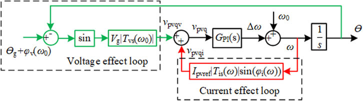
FIGURE 8. Control diagram of SRF-PLL.
Figure 9 shows the maximum current required by the stability condition in (12). When the current in a real system exceeds the curve, frequency control loses its stability. It can be seen that the series compensation can ensure the existence of an equilibrium point at the fundamental frequency by eliminating the maximum current limitation, while the parallel compensation cannot. In addition, the maximum current curves decrease as the system short circuit ratio (SCR) and related reactive power compensation increase, which means that system probably becomes unstable when system frequency deviation caused by some large disturbance results in inverter current exceeding the maximum limitation at some frequency points.
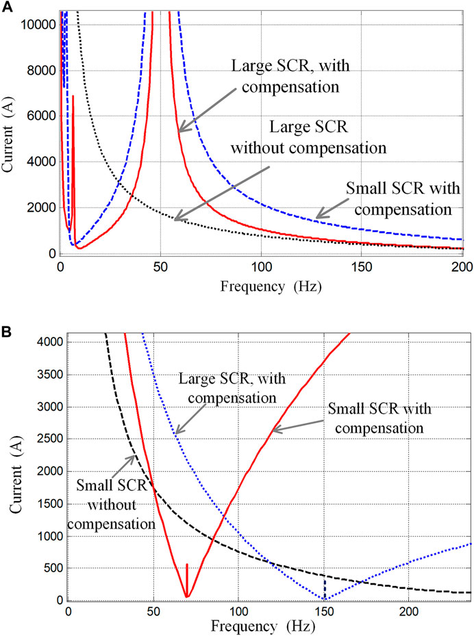
FIGURE 9. Stability limitation to frequency control with different compensation conditions. (A) Series capacitor compensation. (B) Parallel capacitor compensation.
4 Stability improvement methods
The analysis in Section II and Section III indicates that a weak power grid can cause PV system DC and AC voltage instability. Series and parallel compensation are able to solve the voltage instability problem. However, when grid strength is ultra-weak, that is, a large amount of reactive power is required, reactive power compensation will induce frequency control instability problems. As the frequency instability caused by reactive power compensation depends on the system frequency deviation range and compensation forms, this paper proposes stability improvement methods from the perspective of frequency damping and reactive power compensation collaboration. Compared with the existing methods, the methods proposed in this paper rely little on detailed system modeling and will not influence the system’s original control requirements.
For the constant grid impedance, Figure 10A shows the maximum current curves with different reactive power compensation. It can be seen that the collaboration of series and parallel compensation can improve the maximum current curve compared with parallel compensation. However, the stability region in the higher frequency range is reduced compared with series compensation. Curves with different reactive power allocations are shown in Figure 10B to investigate the influence of the allocation of reactive power among series and parallel compensation on the maximum current curve. This figure shows that for a constant grid impedance, increasing parallel compensation moves the maximum current curve toward a lower frequency range, which reduces the stability range above the fundamental frequency but enlarges the range less than the fundamental frequency. Therefore, the allocation of reactive power compensation should be made according to the system frequency deviation range. More parallel compensation allows more frequency deviation in the lower frequency range. By the same token, more series compensation is beneficial for the system with large higher frequency disturbance.
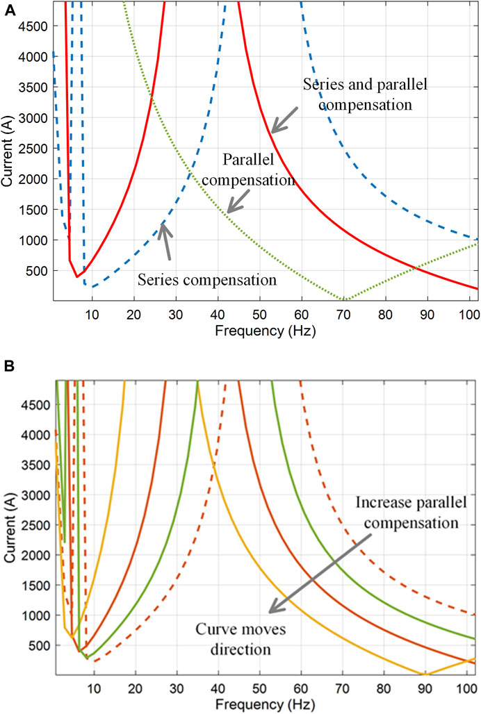
FIGURE 10. Maximum inverter current curves. (A) With different reactive power compensation. (B) With different allocation among series and parallel compensation.
Even though the proper allocation of series and parallel compensation can improve frequency stability for different frequency disturbance directions, the maximum range is restricted. Therefore, some methods to restrict system frequency deviation must be proposed.
The methods to restrict system frequency deviation can be realized by reducing PI parameters inside the PLL control. However, the reduction of PI parameters usually leads to slow system response time, which will further influence inner current control (Hamed et al., 2017). The function of reducing PI parameters on frequency control can be equivalently transformed into an AC circuit. As the main purpose of reducing PI parameters is to limit the frequency deviation range by filtering out the undesired frequency components, the same function can also be realized outside the PLL, such as a band-pass filter in series in front of the PLL. In addition to the traditional methods, intelligent control, such as fuzzy control, can also effectively restrict system frequency deviation because of its better performance in regulating control error and the time ratio of error. The band-pass filter and fuzzy control in improving system stability are shown in Figure 11.
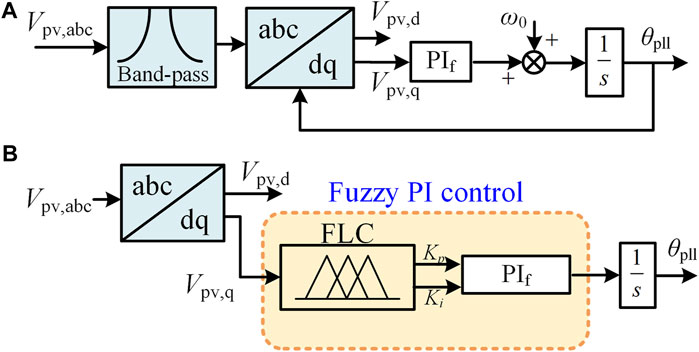
FIGURE 11. Methods of restricting frequency deviation. (A) Band-pass filter. (B) Fuzzy PI control.
The band-pass filter can be expressed by
where ωn is the fundamental frequency. ξ represents the damping ability of non-fundamental frequencies, and a small ξ has a better filtering ability. Therefore, systems with a large frequency deviation need smaller ξ to improve frequency control stability.
The input signal of fuzzy control is Vpv,q and the time ratio of Vpv,q. Taking the fuzzy linguistic variables as [NB NM NS Z PS PM PB], the Gaussian function is adopted as the membership function. The fuzzy decision on Kp and Ki is given by the center of gravity (COG) method, which is shown in (14). In (14), r is the number of fuzzy rules; xk and yk are, respectively, the state and input variables; Kp,i and Ki,i are the discrete elements of the output fuzzy set; Fj is the membership function of the jth rule. With the aforementioned definition, the detailed design can be conveniently realized with the help of the fuzzy toolbox in MATLAB.
5 Simulations and experiments
5.1 Simulations
A 500-kW grid-connected PV system is built in MATLAB Simulink to verify the theories proposed in this paper. The inverter output voltages and currents are shown in Figure 12, where the grid impedance was enabled and increased at the time constants of 0.2 s and 0.4 s to simulate the weak power grid. The simulation shows that increasing grid impedance reduces inverter voltage, and large impedance causes system instability. The simulation results have verified the voltage problem in a PV system.
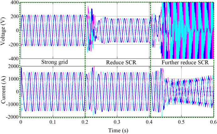
FIGURE 12. Inverter voltage and current under different grid strength.
Series and parallel compensation are used to solve the voltage stability problem. Figure 13 shows the compensation results with system SCR reduced from 2.3 to 1.2 at 0.25 s. It verifies that parallel and series compensation can effectively compensate inverter voltage to the normal level, but it causes system control instability for smaller SCR systems, where the inverter current and voltage become uncontrollable, and the system frequency appears to oscillate.
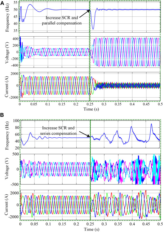
FIGURE 13. PV system simulation under different grid strengths and reactive power compensation methods. (A) Parallel compensation. (B) Series compensation.
For the frequency instability caused by reactive power compensation, the series and parallel compensation were combined to each provide half of the reactive power to the grid inductor. The band-pass filter and fuzzy PI were used to limit system frequency deviation. Figure 14 shows that both band-pass filter and fuzzy PI control can solve the frequency instability caused by reactive power compensation.
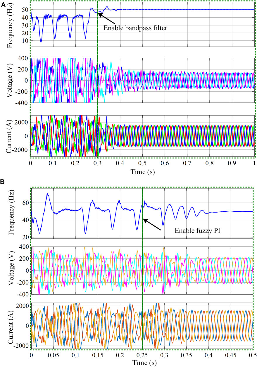
FIGURE 14. Simulations with different stability improvement methods. (A) Band-pass filter. (B) Fuzzy PI.
5.2 Experiments
The experimental system is built by Rtunit Box and dSPACE Box. The 500-kW power circuit is realized in the dSPACE box, and the control circuit is implemented by RT unit Box, whose inside controllers are DSP TMS320C28346.
The influence of the weak power grid on inverter voltage was first verified, as shown in Figure 15A. It can be seen that increasing grid impedance reduces inverter voltage. The series and parallel compensation were then deployed to solve the voltage problem, as shown in Figure 15B. It shows that reactive power compensation can improve system voltage for large SCR systems. However, if further reducing SCR and improving reactive power compensation, the frequency control becomes unstable, which results in system overall oscillation, as shown in Figure 15C. The experimental results have verified that reactive power compensation causes frequency instability for small SCR systems, even though it can solve system voltage problems. The stability improvement methods were deployed to solve the frequency instability, and the experimental results are shown in Figure 15D. It shows that using the stability improvement methods proposed in this paper can effectively ensure system stability even if system SCR is reduced. This is because the proposed methods can effectively restrict system frequency deviation and thus successfully keep the system operating in the stability region.
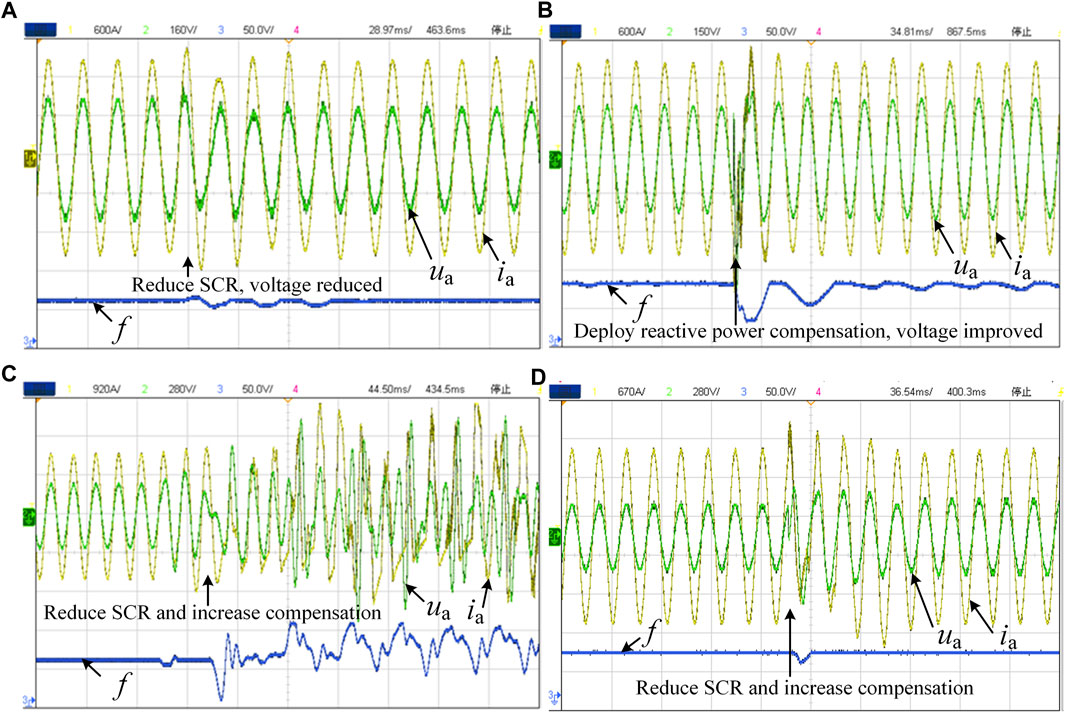
FIGURE 15. Voltage, current, and frequency of PV inverter. (A) Reducing system SCR. (B) Applying reactive power compensation for a large SCR system. (C) Applying reactive power compensation for a small SCR system. (D) Deploying stability improvement methods for a compensated small SCR system.
6 Conclusion
The work in this paper reveals and solves the frequency stability problems caused by reactive power compensation, which can help improve system voltage and frequency stability in large PV systems. Voltage in large PV systems is influenced by grid strength. Small SCR reduces PV voltage and probably causes voltage instability. Reactive power compensation is an effective way to ensure that system voltage operates in the normal range. Series compensation is necessary for an ultra-weak grid because of the limitation to parallel compensation. However, reactive power compensation, whether it is parallel or series compensation, threatens system frequency stability. A system that needs large reactive power compensation usually has the risk of frequency control instability. A band-pass filter and fuzzy control have been proposed to solve the frequency control instability. Simulations and experiments have verified the correctness of the proposed solution.
Data availability statement
The original contributions presented in the study are included in the article/Supplementary Material; further inquiries can be directed to the corresponding author.
Author contributions
QZ: proposing ideas, simulation and experiment, organizing and writing article. QH: analysis, simulation, and writing. SS: analysis, simulation, and writing. DM: analysis and simulation. SL: analysis and discussion. XL: analysis and discussion. All authors contributed to the article and approved the submitted version.
Funding
This work was supported in part by the Natural Science Foundation of Anhui Colleges under grants 2022AH050326 and KJ2021A0370, and the Science Foundation of Anhui University of Technology under Grant QZ202106.
Conflict of interest
The authors declare that the research was conducted in the absence of any commercial or financial relationships that could be construed as a potential conflict of interest.
Publisher’s note
All claims expressed in this article are solely those of the authors and do not necessarily represent those of their affiliated organizations, or those of the publisher, the editors, and the reviewers. Any product that may be evaluated in this article, or claim that may be made by its manufacturer, is not guaranteed or endorsed by the publisher.
References
Ai, Y., Du, M., Pan, Z., and Li, G. (2021). The optimization of reactive power for distribution network with PV generation based on NSGA-III. CPSS Trans. Power Electron. Appl. 6 (3), 193–200. doi:10.24295/cpsstpea.2021.00017
Du, C., Du, X., Zhou, X., and Tang, J. (2020). Impedance modeling and stability analysis of grid-connected modular multilevel converter considering frequency coupling effect. Proc. CSEE 40 (9), 2866–2877. doi:10.13334/j.0258-8013.pcsee.191703
hafiullah, M., hmed, S., and Al-Sulaiman, F. A. (2022). Grid integration challenges and solution strategies for solar PV systems: A review. IEEE Access 10, 52233–52257. doi:10.1109/access.2022.3174555
Hamed, H. A., Abdou, A. F., Bayoumi, E. H. E., and El-Kholy, E. E. (2017). A fast recovery technique for grid-connected converters after short dips using a hybrid structure PLL. IEEE Trans. Industrial Electron. 65 (4), 3056–3068. doi:10.1109/tie.2017.2764856
He, X., Pan, S., and Geng, H. (2022). Transient stability of hybrid power systems dominated by different types of grid-forming devices. IEEE Trans. Energy Convers. 37 (2), 868–879. doi:10.1109/tec.2021.3113399
Huang, Y., Yuan, X., Hu, J., Zhou, P., and Wang, D. (2016). DC-bus voltage control stability affected by ac-bus voltage control in VSCs connected to weak ac grids. IEEE J. Emerg. Sel. Top. Power Electron. 4 (2), 445–458. doi:10.1109/jestpe.2015.2480859
Lasseter, R. H., Chen, Z., and Pattabiraman, D. (2020). Grid-forming inverters: A critical asset for the power grid. IEEE J. Emerg. Sel. Top. Power Electron. 8 (2), 925–935. doi:10.1109/jestpe.2019.2959271
Lee, K. Y., and Yang, F. F. (1998). Optimal reactive power planning using evolutionary algorithms: A comparative study for evolutionary programming, evolutionary strategy, genetic algorithm, and linear programming. IEEE Trans. Power Syst. 13 (1), 101–108. doi:10.1109/59.651620
Liu, L., Li, H., Xue, Y., and Liu, W. (2015). Reactive power compensation and optimization strategy for grid-interactive cascaded photovoltaic systems. IEEE Trans. Power Electron. 30 (1), 188–202. doi:10.1109/tpel.2014.2333004
Liu, Y., Chen, L., and Han, X. (2022). The key problem analysis on the alternative new energy under the energy transition. Proc. CSEE 44 (02), 515–524.
Liu, Z., Qu, K., and Zhao, J. (2022). Analysis of the small-signal stability for multiple grid-connected-converter system based on brauer theorem. Proc. CSEE 42 (2), 515–524.
Qi, Y., Deng, H., Fang, J., and Tang, Y. (2022). Synchronization stability analysis of grid-forming inverter: A black box methodology. IEEE Trans. Industrial Electron. 69 (12), 13069–13078. doi:10.1109/tie.2021.3137608
Reshikeshan, S. S. M., Matthiesen, S. L., Illindala, M. S., Renjit, A. A., and Roychowdhury, R. (2021). Autonomous voltage regulation by distributed PV inverters with minimal inter-node interference. IEEE Trans. Industry Appl. 57 (3), 2058–2066. doi:10.1109/tia.2021.3064911
Sarkar, M. N. I., Meegahapola, L. G., and Datta, M. (2018). Reactive power management in renewable rich power grids: A review of grid-codes, renewable generators, support devices, control strategies and optimization algorithms. IEEE Access 6, 41458–41489. doi:10.1109/access.2018.2838563
Sonawane, A. J., and Umarikar, A. C. (2022). Small-signal stability analysis of PV-based synchronverter including PV operating modes and DC-link voltage controller. IEEE Trans. Industrial Electron. 69 (8), 8028–8039. doi:10.1109/tie.2021.3109506
Sridhar, R., Vishnuram, P., Bindu, D. H., and Divya, A. (2016). Ant colony optimization based maximum power point tracking(MPPT) for partially shaded standalone PV system. IJCTA 9 (16), 8125–8133.
Sudharshan, Konduru, Naveen, C., Vishnuram, P., Krishna Rao Kasagani, D. V. S., and Nastasi, B. (2022). Systematic review on impact of different irradiance forecasting techniques for solar energy prediction. Energies 15 (17), 6267. doi:10.3390/en15176267
Sun, J. (2011). Impedance-based stability criterion for grid-connected inverters. IEEE Trans. Power Electron. 26 (11), 3075–3078. doi:10.1109/tpel.2011.2136439
Wang, G., Du, X., Zhou, X., Yang, Y., and Ji, Y. (2017). Self and accompanying admittance model for three-phase grid-tied inverter stability analysis. Proc. CSEE 37 (14), 3973–3981. doi:10.13334/j.0258-8013.pcsee.170448
Wang, X., Harnefo, R. S., and Blaabjerg, F. (2018). Unified impedance model of grid-connected voltage-source converters. IEEE Trans. Power Electron. 33 (2), 1775–1787. doi:10.1109/tpel.2017.2684906
Wang, Y., Wang, X., Blaabjerg, F., and Chen, Z. (2017). Harmonic instability assessment using state-space modeling and participation analysis in inverter-fed power systems. IEEE Trans. Industrial Electron. 64 (1), 806–816. doi:10.1109/tie.2016.2588458
Wei, W., Xia, Y., and Blaabjerg, F. (2020). Nonlinear stability analysis for three-phase grid-connected PV generators. IEEE J. Emerg. Sel. Top. Power Electron. 8 (4), 3487–3501. doi:10.1109/jestpe.2019.2939379
Yang, D., Wang, X., Liu, F., Xin, K., Liu, Y., and Blaabjerg, F. (2019). Adaptive reactive power control of PV power plants for improved power transfer capability under ultra-weak grid conditions. IEEE Trans. Smart Grid 10 (2), 1269–1279. doi:10.1109/tsg.2017.2762332
Zhang, Q., Mao, M., Guo, K., Zhou, L., and Xie, B. (2020). Stability problems of PV inverter in weak grid: A review. IET Power Electron. 13 (11), 2165–2174. doi:10.1049/iet-pel.2019.1049
Zhang, Q., Qian, J., Zhai, Z., Liu, X., Liu, S., Fang, W., et al. (2022). Control stability of inverters with series-compensated transmission lines: Analysis and improvement. J. Power Electron. 22 (10), 1746–1757. doi:10.1007/s43236-022-00488-w
Zhang, X., Li, M., Guo, Z., Wang, J., Han, F., and Fu, J. (2021). Review and perspectives on control strategies for renewable energy grid-connected inverters. J. Glob. Energy Interconnect. 4 (5), 506–515. doi:10.19705/j.cnki.issn2096-5125.2021.05.010
Zheng, K., Zhou, L., Zhang, Q., and Xie, B. (2018). Stability analysis and parameter optimization design of photovoltaic grid-connected inverter under digital control. Trans. China Electrotech. Soc. 33 (8), 1802–1813.
Zhou, L., Ren, W., Liao, B., and Chao, Y. (2015). Reactive power and voltage control for grid-connected PV power plants. Trans. China Electrotech. Soc. 30 (20), 168–175.
Keywords: large PV system, inverter, voltage regulation, frequency control, stability
Citation: Zhang Q, Hu Q, Sun S, Mei D, Liu S and Liu X (2023) Voltage and frequency instability in large PV systems connected to weak power grid. Front. Energy Res. 11:1210514. doi: 10.3389/fenrg.2023.1210514
Received: 22 April 2023; Accepted: 30 May 2023;
Published: 13 June 2023.
Edited by:
Salah Kamel, Aswan University, EgyptReviewed by:
Pradeep Vishnuram, SRM Institute of Science and Technology, IndiaTohid Rahimi, Carleton University, Canada
Copyright © 2023 Zhang, Hu, Sun, Mei, Liu and Liu. This is an open-access article distributed under the terms of the Creative Commons Attribution License (CC BY). The use, distribution or reproduction in other forums is permitted, provided the original author(s) and the copyright owner(s) are credited and that the original publication in this journal is cited, in accordance with accepted academic practice. No use, distribution or reproduction is permitted which does not comply with these terms.
*Correspondence: Qianjin Zhang, WnFqMTIxNEBhaHV0LmVkdS5lZHU=