 Shuqing Zhang
 Xianfa Hu
 Xianggang He2
 Haibo Li
 Donghui Zhang
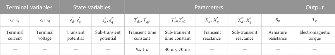

95% of researchers rate our articles as excellent or good
Learn more about the work of our research integrity team to safeguard the quality of each article we publish.
Find out more
ORIGINAL RESEARCH article
Front. Energy Res. , 23 June 2023
Sec. Smart Grids
Volume 11 - 2023 | https://doi.org/10.3389/fenrg.2023.1209845
This article is part of the Research Topic Model and Simulation, Dynamic and Transient Analysis, Stability Control of Microgrids with New Forms and Features View all 9 articles
A multi-energy (ME) system can coordinate local energy sources and users and optimize the supply of various energy forms, to maximize the comprehensive utilization efficiency of energy. As the scale of the multi-energy system becomes more extensive and the physical connections of different energy forms become diversified, the coupling of various forms of energy becomes closer. Such development has brought significant challenges to safe operations and effective regulation of the system and equipment. However, no efficient and easy-to-use dynamic simulation method is available for multi-energy systems. It has become an urgent problem how to fully use the existing rich models and algorithms of conventional energy systems to construct the dynamic simulations of multi-energy systems. Based on the multi-energy system’s structure, components, and model characteristics, this paper studies the mechanism of cross-energy-form dynamic coupling, proposes the critical techniques of multi-energy hybrid simulation and verifies the effectiveness and accuracy of the methods through case tests.
In the traditional energy system, obvious boundaries separate different energy forms so that various energy systems are almost isolated during operation and management. As a result, energy conversion, transmission, supply, and utilization are neither flexible enough nor efficient. A new energy architecture - “energy internet” -borrowed the thoughts and ideas of the internet and came into being. It is a cyber-physics-grounded integrated energy supply and utilization system that promotes energy structure adjustment and significantly improves energy conversion, transmission, distribution, and integrated terminal utilization. The ME system, composed of a cooling, heating, and power integrated energy system, gas supply system, and energy storage system, constitutes the main physical body of the energy internet.
According to local circumstances and energy needs, many energy systems integrated with various energy forms have been built worldwide. Some of these practical energy projects have taken shape and initially gained benefits (Bai et al., 2019). has analytically proved the technical and economic feasibility of the ME microgrid. The combined cooling, heating, and power (CCHP) system is the most typical and common ME system. Here are some successful examples in the world. Princeton University thermal power station and the Busch thermal power station of New Jersey University achieved a combined energy utilization rating of up to 75%–80% (Ma and Zhong, 2003) Other energy projects where the energy utilization rate reached 75% are the CCHP station of Huangpu District Central Hospital in Shanghai and the CCHP station of Pudong International Airport. Some projects have also seen a higher return rate on investment than traditional energy supply modes. E.g., for the ME station of the Shanghai business street project, the return rate on investment reached 11.3% (He et al., 2020).
The ME system combines, transforms, and supplies loads of different needs and features with various energy types. The generated surplus energy is temporarily stored in storage equipment. Energy subsystems and devices are connected to form a whole energy system. The energy flows and transfers in the energy system, and different forms of energy are transformed at the sources and utilized by the loads. As we can see, energy devices and subsystems of varying energy forms have interaction and coupling in the ME system.
According to the research concern and physical characteristics in application scenarios, ME coupling can generally be classified into static and dynamic types.
On the one hand, the system achieves energy balance everywhere and conservation of the total energy, which belongs to the category of static ME coupling. The research and practices on ME systems involve idea verifying, system planning, designing, operation optimization, validation of networking structure, and so on. This stage focuses on technical feasibility, economic viability, source-load matching, and optimization of energy transportation path. Technically, we are always concerned with combining and matching ME sources and loads under various operating conditions, parameter configuration, system-level static stability, etc. For example, fully considering steady-state coupling characteristics among energy sources, Wang et al. (2021) has proposed a ME system planning method to reduce the entire life cycle cost and promote the economic benefit rata and the new energy consumption rate (Wang S. X. et al., 2021). has pointed out that the multi-energy coupling was the key to the load forecasting for regional integrated energy systems and proposed a ME load forecasting method using the ME coupling variation curves. Much work has been devoted to the operation of the ME systems, for example, optimal partition dispatching based on locational marginal price (Jin et al., 2021) and optimal dispatching based on the fuzzy decision (Gao et al., 2021). Going one step further, some researchers have realized the complexity of ME systems and tried to push the operation and dispatching methods toward practical applications. E.g., based on the steady-state coupling and constraints, a multi-time scale optimization dispatching method has been configured (Li P. et al., 2021), including real-time, intra-day, and day-ahead dispatching. Operational risk and security have also attracted wide attention. Li et al. (2021) has established the operation security region based on ME flow energy balance equations and security inequality constraints and then developed the multi-objective control strategy for the operation of ME systems. Researchers with the Stevens Institute of Technology Hoboken United States have probed risk-averse coordinated operation for a ME microgrid by voltage and thermal flow control (Li et al., 2020). Work in (Zhong et al., 2021) has developed an emergency control strategy for the blackout of distributed ME systems, considering the static coupling across various energy forms and capacities of controllable equipment.
On the other hand, the physical dynamics and transients constrain the operation of ME systems during energy conversion and transmission. The regulation of major equipment also involves dynamic and transient. Thus, dynamic coupling exists among different forms of energy systems and equipment. Studies have preliminarily discussed and summarized the ME flow dynamic coupling path and qualitative characteristics (Yu et al., 2017).
The dynamic coupling lays the foundation for the calculation of the operation schedule. The paper (Yao et al., 2020) has built a simplified model combining the gas system’s minute- and hour-level dynamics and embedded it into the power system day-ahead scheduling model to take the system risk and operation security into account. Similarly, the paper (Yang et al., 2017) has derived the transient heat flow model and combined the steady state electrical power flow model to obtain the dynamic energy flow model for a type of ME system used for optimal system operation. The ME flow model has well-balanced calculation precision and complexity. Along with projects of ME systems completed and placed into service, problems related to system security and stability caused by dynamic coupling are more prominent. People have begun to pay attention to the dynamic stability and regulation of ME systems. Zhou et al. (2021) has developed autonomous cooperative control for a ME system comprised of AC/DC microgrid and ice-based cooling storage, considering dynamic coupling between electric and heat. Zhou et al. (2021) has pointed out that dynamic controls are the key to maintaining stable operation and achieving various gadgets. The authors (Perilla et al., 2020) have noticed the collateral effects on stability phenomena and developed active power gradient control for multi-energy devices to ensure system stability. Aiming at the high wind power percentage uncertainty, the paper (Sun et al., 2021) has coordinated sources, including battery storage and regenerative electric boiler, further developed stability and robust control for an ME system.
The above initial attempts have bespoken that the complex dynamic interaction among different energy for MS is likely to be aroused by complex ME interaction, complex sequential control, and comprehensive frequency band response. The ME devices are also dynamically coupled in various forms and through multiple paths. These have made it quite challenging to analyze and study the ME system’s behaviors, characteristics, and operation controls. Thus, the analysis and study depend on quantitative and accurate means, such as dynamic simulation.
There are relatively mature and widely used analysis and calculation methods and techniques in energy fields for each single energy form. For example, the electrical power system and microgrid simulations have successfully tackled various engineering problems. Such as power flow and static stability, quasi-steady states analysis, electromagnetic transient stability, electromechanical transient stability, and medium and long-term stability. Taking the representative thermal energy system as an example, the simulation techniques of the non-electrical systems fall into two broad categories: simulation at the component-equipment level (Butz and Stephan, 1989; Zhuo, 1994; Herold et al., 1996) and the equipment-system level (Yang et al., 2017; Yu et al., 2017; Yao et al., 2020).
Generally, most current research and application of equipment-system level simulation still focuses on static analysis, while component-equipment level simulation partly deals with dynamic analysis. Much work on the latter topic has supplied the system-level simulation with many dynamic models and has laid the model and algorithm basis for system-level simulation.
Some preliminary work has initialized the research and applications of dynamic modeling and simulation of ME systems, e.g., analysis of dynamic behavior and control of the combined cooling heating and power system (Rosato et al., 2013). However, the thermal and power system models are cursorily spliced together—separately modeling the different energy forms and solving them by exchanging boundary outputs. Besides, the thermal models are greatly simplified - only considering the working medium flow and neglecting or approximating the heat transfer process, changes of working medium state and property, etc. As a result, traditional ME simulations incur significant errors.
Up to now, two methods have been commonly used in the dynamic simulation modeling of multi energy systems: 1) Unified step modeling method: focusing on the dynamic process of the thermal system (with a relatively large time scale), ignoring the electromechanical transient process of the power system (with a small time scale). To ensure the computational efficiency of the system model, the power system often adopts steady-state modeling method, The calculation data interaction of the thermoelectric coupling interface model adopts a unified step size (solving step size of the thermal system) interaction. Although it can simulate the impact of large disturbances in the thermal system on the power system to a certain extent, it cannot simulate the transient change process caused by power system faults at the moment; 2) The mixed step modeling method for interfaces. In order to establish the ability to analyze the transient changes of a multi-energy system under disturbances in the thermal system and faults in the power system, while improving computational efficiency, different simulation step size modeling methods are used for systems at different time scales. The thermal system uses large step size solutions, while the power system uses small step size calculations. The interface model data interaction occurs at the end of the large step size, and this method has a small error in the data interaction of the electrical thermal weak coupling interface, However, for the thermoelectric coupling interface with strong coupling, the error is relatively large.
In response to the shortcomings of the interface modeling methods mentioned above, this paper summarizes the basic structure, elements, and typical characteristics of the ME system in part 2. Then, It focuses on studying the mechanism and characteristics of dynamic coupling under different energy forms from the perspectives of energy conversion relationships, structural characteristics of cross attribute energy coupling, time scale and intensity of interactions, and categorizes cross attribute energy interfaces In part 3. In part 4, it proposes a hybrid simulation scheme and fundamental interface techniques based on analyzing and comparing the similarities and differences of various energy dynamic simulation models with solution algorithms, and focused on analyzing the methods and data interaction of the typical three types of interfaces summarized in part 2. Finally, the paper realizes the dynamic simulation of ME systems, fully utilizing the existing dynamic models and solution algorithms from traditional energy systems.
A ME system comprises integrated energy equipment, including cooling, heating, and electrical equipment, natural gas pipelines, and energy storage units, which features the diversity of energy forms in source-grid-load-storage links of the energy internet. The elements constituting the ME system fall into four categories. 1. Sources, power devices directly provide energy in heat, cold, electricity, gas, or equipment converting energy from one form to another. 2. Grids are the medium and path of energy transmission in multiple energy forms, such as thermal pipelines, electrical networks, gas pipelines, etc., 3. Loads include users’ various energy needs. Notably, the load of one energy form may be a source of another, such as electric boilers serving as a load in the electrical system and a source in the thermal system. 4. Storages mainly refer to various storage facilities.
In addition, energy conversion equipment falls into a particular type, through which multiple energy forms are coupled. The energy conversion components (gas turbines, combined heat and power generations, gas-fired heating boilers, electric-thermal loads, and storage devices) divide the ME system into different conventional energy subsystems. Different energy subsystems and equipment interact and couple through energy-converting elements in the ME system. While in single-form or single-form-dominated traditional systems, energy-converting components often serve as the ideal boundary for analysis and calculation.
1) Physical structure
The ME elements are connected according to the physical relationship to form the typical structure of the ME system shown in Figure 1. A ME system mainly comprises a power system, a thermal system, and a fuel-pipe grid. Various energy systems are composed of energy transmission grids and energy dynamic elements connected to grids. Different types of energy systems are connected through energy conversion equipment. E.g., in the gas-turbine-centered CCHP equipment group, the gas turbine burns natural gas to drive the generator to generate electrical energy. The exhaust gas sends the heat energy to the thermal system through the heat recovery boiler or drives the lithium bromide absorption chiller for cooling.
2) Calculation structure: trunk-branch-leaf three layers
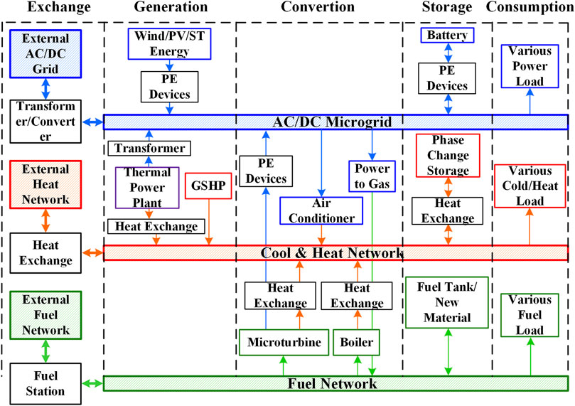
FIGURE 1. Typical structure of the ME system.
We can roughly divide the ME system into three layers according to the networking level and connection relationship shown in Figure 2.
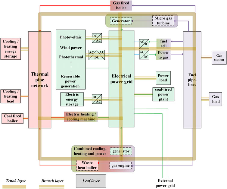
FIGURE 2. Trunk-branch-leaf three-layer calculation structure.
The trunk layer is at the top of the ME system, where diverse forms of energy are converted and transformed, and ME equipment interacts and couples. In the dynamic simulation, the trunk layer focuses on the dynamic coupling among grids of different energy forms.
The branch layer is in the middle of the ME system, containing multiple “branches”. One branch represents a form of the energy grid, such as a power grid, heat pipe, gas pipeline, etc. In the dynamic simulation, the branch layer focuses on simultaneously solving the component models connected to the same energy grid.
The leaf layer, the bottom of the ME system, involves all the energy components. In the dynamic simulation, the leaf layer focuses on solving component models and dealing with the coupling within any energy element.
The existing dynamic simulation of every single type of energy system has a relatively affluent model and algorithm basis, which means that ME simulation can employ mature models and algorithms for the branch layer and leaf layer. To fully utilize existing model and algorithm resources to facilitate dynamic modeling of ME systems, it is necessary to briefly sort out the models and algorithms of different forms of energy systems. The coupling and algorithm characteristics of a heating system (a typical non-electrical system) and a electrical power system are compared as follows.
1) Components and equipment are connected and coupled through the electrical grid and component-grid interfaces.
2) The nonlinearity of power systems mainly results from the physical characteristics of special equipment and circuit topology changes. It is usually solved through local linearization, interpolation, or compensation, etc.
3) Dynamic long process involves multi-time scale phenomena, usually calculated by superposition.
1) Thermal equipment and components are directly coupled through input and output.
2) The nonlinearity of thermal systems comes from the total volume and physical characteristic equations of thermal equipment and components. The nonlinearity combines the model equations of a thermodynamic system into higher-order equations. It can be solved by Newton’s algorithm and its improved algorithm, continuation algorithm, secant algorithm, and their combination.
3) Dynamic long process comes from working medium state changing, usually disposed of by effective splicing.
Energy conversion among different forms happens through different paths, and thus the coupling modes across systems are more diverse, as summarized in Figure 3, mainly include:
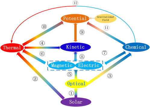
FIGURE 3. ME conversion paths.
1–5: solar photovoltaic effect electrical power generation;
2-4-8: solar thermal power generation; wind power generation;
2-10-9-8: hydroelectric generation;
12: steam turbine, internal combustion engine, boiler, etc. - convert fuel into heat energy;
12-4-8: coal-fired power generation, oil-fed electric generation, gas-fired electric generation, nuclear power generation, and biomass power generation;
9–8: tidal power generation;
8–9: compressed air energy storage;
8–9 and 9–8: power generation from pumped hydro and compressed air energy storage;
Figure 3 shows that energy is transformed among the common energy forms, including thermal, mechanical, solar, chemical, electric, and magnetic. Due to the limitations of energy transmission and the users’ needs, solar and mechanical energy only appear at the primary source or the intermediate link of energy transformation and do not enter the energy networks.
Different energy forms interact, transform, and combine in the trunk layer. Figure 4 Summarizes the boundaries across energy forms, assuming that the energy system comprises networks of three energy forms: cold and heat, electricity, and gas. The three energy forms are coupled on the boundaries where networks intersect. There are some examples: electricity and gas energy forms interact through fuel cell and electrolytic hydrogen production; electricity and heat couplings exist in thermal power generation and electric boilers; and heat and gas couplings include internal combustion engine gas-fired boilers, etc.
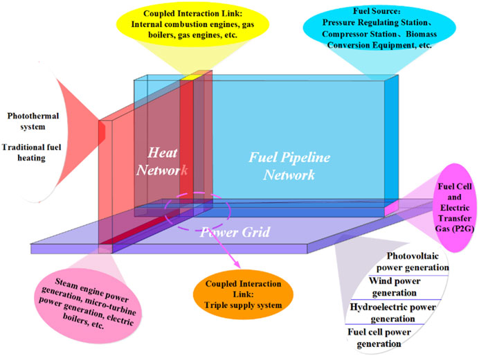
FIGURE 4. ME coupling boundaries.
In addition, coupling also exists within the same energy forms in a ME system, mainly in the tree and leaf layers.
The equipment and devices in the branch layer of the same energy form are linked through the equipment-network interface or directly connected. The interaction and coupling among the equipment and devices happen directly or through the network. For example, the power supply, load, and electronic devices are connected to the grid in the power system, and the interaction and coupling path is the power grid. Therefore, in the dynamic simulation, the simultaneous solution of the equipment models can be achieved by the equipment-network interface.
The leaf layer contains many energy devices where interaction and coupling between components and elements occur. Interface variables and coupling equations often describe this interaction and coupling in modeling.
As shown in Figure 5, the time scales of the leading dynamic processes in typical ME systems are summarized.
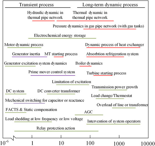
FIGURE 5. Time scale of dynamics processes in the ME system.
The dynamic response covers a considerable time scale. Equipment level dynamics contain fast processes - the electromagnetic and electromechanical transient processes in electrical power equipment from microseconds to hundreds of milliseconds, and slow processes - heat exchange dynamic processes in thermal equipment from tens of minutes to hours. System level dynamics also contain relatively fast processes: power grid low-frequency oscillation and frequency stability processes on the order of hundreds of milliseconds, and relatively slow processes: hydrodynamic process and heat conduction in the thermal pipe network and gas pipe network on the order of seconds to tens of minutes. It can be seen that equipment and networks of different energy forms interact and couple with others on broad time scales.
The overlapped response time spans Intuitively represent dynamic interaction and coupling among energy systems of different forms. Specifically, the dynamic response time scale of thermal and electrical coupling covers the range of seconds to tens of minutes. The dynamic response covers several seconds in situations where the prime mover and power generation interact and the micro gas turbine with regulation and electrical power generator interact. The multiple energy forms interact in minutes, among active power control, load change, dispatching intervention in electrical power systems, and heat exchange processes in the boiler and pipe network. The dynamic response time of electrical, thermal, and gas coupling ranges from a few seconds to tens of seconds. For example, such a dynamic process happens when the pressure fluctuation in the gas pipe network interacts with the micro gas turbine’s mechanical and thermal energy output fluctuation (Yu et al., 2020).
Thus, the ME coupling can be divided into three categories according to the coincidence degree of response time scales in the leading energy transformation process and the capacity of the main equipment participating in the leading processes.
The first category always appears on the energy source side, and the time scale of gas, heat, and electricity coupling is about several seconds to several minutes. Energy systems and equipment interact and couple through source side equipment. E.g., three energy forms are coupled through the gas turbine generator, steam turbine generator, co-generation, and so on. Such a situation yields the electromechanical transient process in the power grid, the energy conversion in the gas turbine, the fluid dynamic process in gas and heat pipe networks, and the heat exchange and conduction process in thermal equipment closely intermixed over the time of several seconds. At the same time, the controls of critical energy equipment interact with each other, such as the local active power regulation and excitation restriction of the power generation equipment, the pressure regulation of the gas node, and the flow/temperature quick adjustment of thermal nodes. Such interaction also occurs between system-level control loops, such as the automatic power generation control and the thermal system’s overall flow and temperature regulation. Considering the wide time scale and coincidence range of the ME coupling and the centralized and high-capacity equipment used on the source side, we infer that the ME coupling on the source side is tight.
It is worth noting that the physical process of ME coupling may involve other intermediate energy forms. When chemical and thermal energy is converted to electrical energy, high-temperature and high-pressure Steam drives the turbine to rotate. Part of the thermal energy is converted into mechanical energy, which is further converted into electrical energy through the electromagnetic induction effect.
On the load side of the electrical system (the source or storage side of the thermal design and the source side of the gas system), coupling among electric, heat, and gas falls into two categories: the second and third types of ME coupling.
The second type of coupling performs on the time scale from seconds to minutes, including the heat energy generated by the electric heat pump and injected into the heat pipe network. Like on the source side, intermediate energy forms, i.e., mechanical energy, appear in the ME coupling path. So, there is a coupling between electrical power and thermal energy on the electromechanical transient time scale. However, the coupling on the load side is relatively weak because distributed and small-capacity equipment is connected here.
The coupling of the third category occurs over a time scale of more than a few minutes. The load and energy storage equipment achieves the conversion and interaction between thermal and electrical energy forms. The coupling strength is the weakest compared with the above two categories. The reason is that the response time of electrical power local control and network is several seconds or less, and the system level control cycle reaches several minutes. In contrast, the primary inertia of heat load and storage and the response time of thermal control is dozens of minutes.
The ME system is divided into subsystems in the trunk layer according to energy forms. The partition locations are often inside energy conversion equipment. Subsystems of different energy forms are simulated using the corresponding models and solving methods. And the interface equivalent models are established at the ME coupling boundary to represent the short-term dynamic response characteristics of other energy systems at each interface interaction interval. Subsystems of different energy forms interact with each other through boundary variables in a specific period and time sequence.
In the hybrid simulation, we separate the whole energy system into two or three subsystems on the ME coupling boundaries, as denoted in Figure 4. Then, we put the equipment and elements of the same energy form together into one subsystem. Essential differences exist in the characteristics of diverse energy forms, and the modeling methods and solving algorithms are also distinct; therefore, the subsystem division is clear and feasible. Furthermore, splitting the system on the ME coupling boundaries helps to fully use the existing mature simulation theory and technology and maintain the mature simulation program architecture of various forms of energy networks.
In the first and second types of ME coupling, thermal and electrical energy systems are coupled through electromechanical processes. The subsystem partitioning interfaces are at the thermal-mechanical and mechanical-electrical energy conversion interfaces. To simultaneously calculate and accurately reproduce the fast coupling processes in hybrid simulation, we should equivalently model the intermediate energy conversion in the thermal-electrical coupling in the two energy systems at the same time. The detailed electrical-mechanical process should be reserved in the electrical energy subsystem featuring fast response, and the thermal-mechanical process be reserved in the thermal energy subsystem. Figure 6 gives the partitioning scheme. This way, the “mapping” models are established for the intermediate components carrying electrical-mechanical-thermal energy conversion processes. For example, a boiler, a steam turbine, and a generator compose the heat and electrical power co-generation system. The turbine converts part of the heat energy into mechanical and electrical energy. Thus, the steam turbine is the intermediary of thermal-mechanical-electrical coupling. Its mechanical-electrical coupling behavior should be modeled in the electrical energy subsystem, and its thermal-mechanical coupling behavior should be modeled in the thermal energy subsystem.
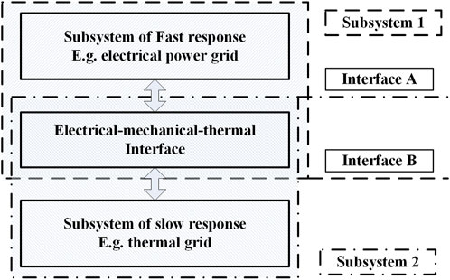
FIGURE 6. System partitioning scheme based on mapping components.
For the third type of ME coupling, the subsystem interface is set inside energy conversion equipment, that is, the interface between components of different energy forms inside the equipment.
As discussed above, subsystems of diverse energy forms are intermixed and coupled in an ME system. The hybrid simulation artificially divides the initially coupled subsystems and solves them independently in the short interval of each interaction step. Therefore, it is necessary to establish ME coupling model pairs and a pair of interface equivalent models at the hybrid simulation partitioning boundary to eliminate or reduce the hybrid simulation interface error.
Modeling of ME coupling is designed for the first and second types of ME strong coupling. Subsystems of diverse energy forms are coupled through energy conversion devices, where the intermediate energy form emerges, and primary energy forms are converted through the intermediate form. Therefore, it is necessary to first establish mapping models for the energy-converting devices in the coupled subsystems, matching each subsystem’s response speed and time scale.
Interface equivalent modeling is employed in one subsystem to represent the port behaviors of the other subsystem at the hybrid simulation partitioning boundaries. During each interaction interval, one subsystem is solved. At the same time, the other subsystem is equivalently modeled at the borders. Hence, the hybrid simulation well keeps the coupling across the ME energy forms within each short interval in each interaction step.
The ME coupling models come from mature models in each energy field and are selected according to the response speed of the major process. For the first and second types of ME coupling, the modeling method is discussed below by taking the thermal-electrical coupling on the source and electrical load sides (thermal source/storage side) as examples.
1. Thermal-electrical coupling on the source side. Typical energy devices are boiler-turbine-generators and gas turbine generators. Here, the former is taken as an example. To effectively and accurately calculate the ME strong coupling, the core idea is to model the components related to the intermediate energy form on both sides of the coupled thermal and electrical subsystems to become mapping model pairs. The structures of the model pairs for the two subsystems are consistent, and the model fineness matches the two subsystems’ response speeds. The generator model, the turbine model, and the corresponding primary control model are established on the electrical energy side, including the electrical part, the rotor motion equation (electrical-mechanical coupling), and the turbine characteristic (mechanical-thermal coupling), shown by formulae (1-6).
<1> Generator transient voltage functions in the electrical subsystem
The physical meanings of the variables and parameters are listed in Table 1.
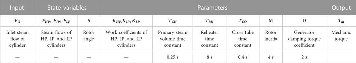
<2> Turbine characteristic equation in both electrical and thermal subsystems
The variables and parameters in Eqs 4–6 are detailed in Table 2. The turbine provides mechanical energy for the generator; thus, the ME components are combined through the turbine, which provides mechanical power for the generator and heat for the thermal system.
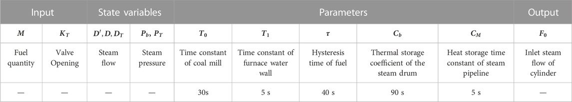
<3> Burning and heat accumulation equations in the thermal subsystem
Table 3 lists the variables and parameters in Eqs 7, 8. The typical values for time constants or inertia constants are also summarized in Tables 2, 3. A simple comparison shows that the time constants of thermal components are much higher than electrical components, while the time constants of mechanical parts are just between the two. The overlapping mapping modeling supplies the ME coupling interaction with a buffer, which makes up the gap between the thermal-electrical coupling in the hybrid simulation and helps improve the accuracy.
2. Electrical load - thermal source/storage coupling through electromechanical processes. The typical equipment groups for the mutual coupling on the boundary are motor-heat pump-heat exchanger systems, given in Figure 7. The electrical energy transfers the heat energy from the low-level heat source to the high-level through the heat pump, and then the high-level heat supplies to the heat load or storage. The electrical and thermal subsystems are strongly coupled through the compressors. Similarly, we should establish mapping model pairs on both sides for the energy device converting intermediate energy form in thermal-electrical coupling.
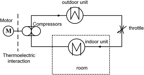
FIGURE 7. Structure of the air source heat pump.
<1> Motor in the electrical subsystem
The variables and parameters in the equation are detailed in Table 4.
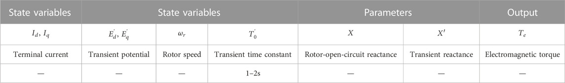
TABLE 4. Variables and parameters in Eq. 9.
<2> Compressor in both electrical and thermal subsystems.
The following analytical formula represents the reduced flow of the compressor (Duan et al., 2015).
where
The following analytical formula represents the reduced efficiency of the compressor (Duan et al., 2015):
The power consumption of the compressor is represented by the following analytical formula (Camporeale et al., 2006):
In (12),
Rotor movement equation
<3> Refrigerant network and load in the thermal subsystem
where
where
The typical parameters reflect the typical response time constant of the abovementioned equipment. It can be seen that mechanical energy becomes the intermediary of thermal-electrical energy conversion in the ME strong coupling. Because the mechanical inertia time constant is close to the response time of some motor armatures’ electromagnetic process in the electrical equipment. Meanwhile, the mass of the thermal working medium directly acting on the mechanical component is small, so the thermal inertia is low, which makes the thermal-electrical coupling relatively strong.
Similarly, we can model the strong coupling and fast interaction among energy forms on both sides of hybrid simulation by mechanical-energy-related devices’ physical or external characteristic equations, including turbines and heat pumps.
Although the mapping models are employed for the thermal-mechanical-electrical coupling, there is still weak coupling at the interfaces for subsystem division (denoted by lines A and B in Figure 6). The equivalent interface models are established to approximate the port response behaviors of other subsystems for a time-step solving of one subsystem. Taking the ME coupling of the boiler turbine generator as an example, the hybrid simulation interface model of thermal-electrical coupling is established.
On the electrical side, the boiler is modeled through a first-order inertia element or a constant output element, equivalent to the boiler’s port response characteristics. On the thermal side, generator windings’ fast electrical transition processes are much quicker than that of the thermal energy system. Therefore, the two-order generator equation is suitable for interface modeling to represent the physical characteristics.
According to sections 4.2 and 4.3, subsystems’ dynamic response time scales show striking differences for the third type of ME coupling. Thus, the subsystems of different forms at the interfaces are weakly coupled. Therefore, to solve one subsystem in each interaction time interval, the subsystem on the other side can be simply represented by the equivalent interface model. It is unnecessary to establish a ME coupling model pair.
Typically, the third type of ME coupling exists in static electrical load-boiler and thermal energy storage. Electrical energy is converted through an electrothermal effect to supply the heating system with energy. Here we take the former as an example to illustrate how to get the equivalent interface model. On the side of the electrical power, the boiler is modeled through a low-order inertia element, which describes the interface response characteristics of the boiler.
On the thermal energy side, the dynamic response of the electrothermal effect is much faster than that of the thermal system. Then, the Thevenin voltage source can model the electrical subsystem representing external characteristics.
The ME coupling models and equivalent interface models describe the coupling characteristics between subsystems. It is necessary to update the latest boundary variables to solve each interaction step as soon as possible. Considering that the thermal subsystem usually uses the maximum solving step, the step shall be taken as the interaction step. Additionally, the solving steps of all subsystems should be well chosen so that the interaction step is the integer multiples of solving steps of all subsystems.
The interaction variables are the interface boundaries, which are yielded by solving interface models. For the third type of ME coupling, the interaction variables are directly the model outputs in all energy subsystems, while for the first and second types of ME coupling, the interaction variables are the boundary variables of the mapping models. This subsection also takes the gas turbine generator of the first ME coupling type as an example; the interface variables are
From Figure 1, we can clearly understand the typical structure and coupling elements of the ME system, including the thermal power plant coupling the thermal and electrical power systems, the internal combustion engine on the power supply side coupling the thermal, electrical, and gas energy, and the heat pump, electric cooker and other electric load equipment on the load side coupling the thermal and electrical energy. Here we employ the co-generation system of a thermal power plant as an example and present its topology in Figure 8. The boiler evaporator generates saturated steam, forming the main steam pressure at the drum outlet. After passing through the superheater, the main steam becomes superheated steam and is collected in the main steam pipeline. It is regulated by the steam inlet regulating valve and enters the high-pressure cylinder to do work. The exhaust of the high-pressure cylinder enters the reheater and is heated into high-temperature reheated steam before entering the intermediate and low-pressure cylinders to do work. The exhaust of the low-pressure cylinder enters the condenser and is condensed into condensate. Steam with a certain pressure and temperature is extracted from the intermediate stage of the low-pressure cylinder through the heating control valve and used for heating. A thermoelectric dynamic coupling model is established according to the method in Section 4.3.2 for the power supply side.
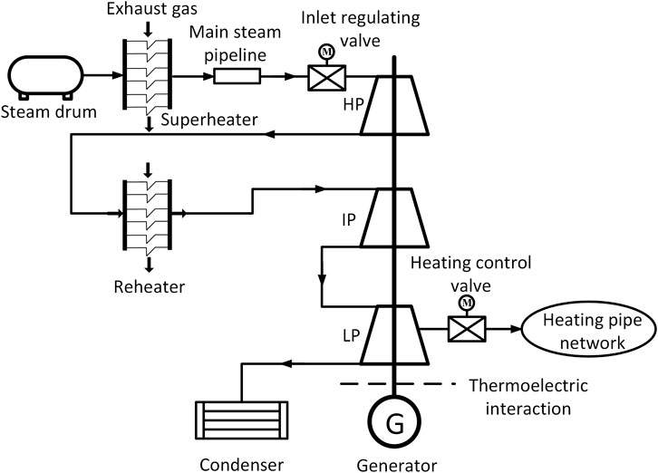
FIGURE 8. Schematic diagram of co-generation system.
Under steady-state operating conditions with a power supply load of 265 MW and a heating steam flow rate of 50T/H, The extraction valve quickly closes at 1 s, and the main steam regulating valve participates in regulation as the power generation load changes, Three equivalent modeling methods for thermoelectric coupling interfaces, namely, unified small step size (0.01s), traditional hybrid step size (0.01s/0.05s), and new hybrid step size (0.01s/0.05s), are used, respectively. Figures 9–12 compare the dynamic curves of the mechanical torque received by the generator on the electrical side and the speed received by the steam turbine on the thermal side under three interaction mechanisms, when the generator terminal voltage drops to 0.2pu, 0.4pu, 0.7pu, and 1pu at 1s and gradually recovers at 2s (Zhang et al., 2017, Xin, 2004).
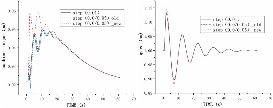
FIGURE 9. Comparison curve of interface interaction data under different interface interaction mechanisms V-0.2pu.
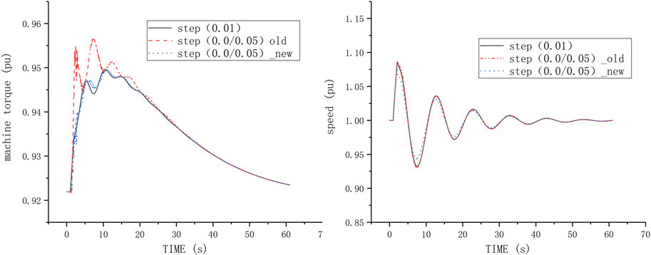
FIGURE 10. Comparison curve of interface interaction data under different interface interaction mechanisms V-0.4pu.
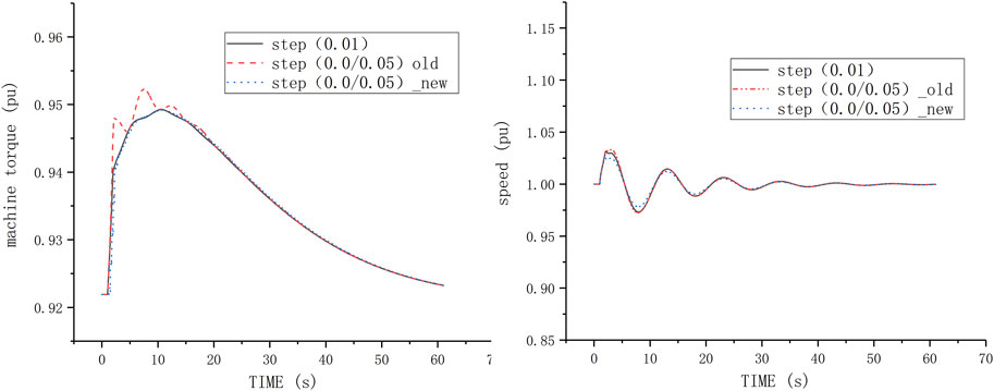
FIGURE 11. Comparison curve of interface interaction data under different interface interaction mechanisms V-0.7pu.
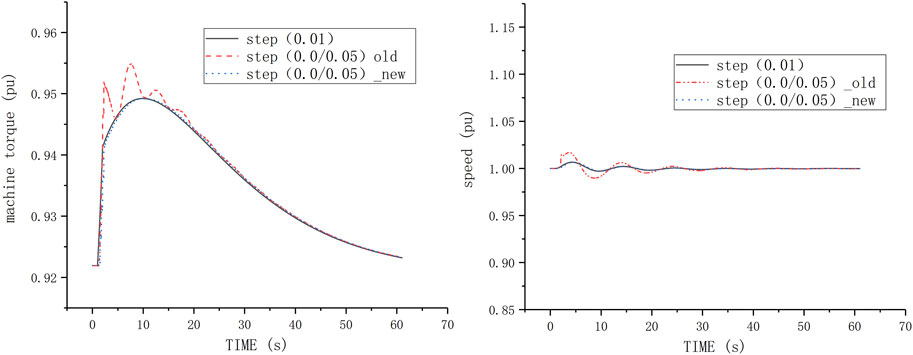
FIGURE 12. Comparison curve of interface interaction data under different interface interaction mechanisms V-1pu.
Figure 9 shows that with a small step size of 0.01s as the benchmark for data interaction, the traditional mixed step size (0.05s/0.01s) interface model has significant errors in data interaction after a fault occurs. When there is no fault set on the electrical side, the traditional hybrid interface modeling method ignores the dynamic change process of the generator in the large step time scale. The electric load value received by the thermal side regulator is the value at the beginning of the large step, and the strong coupling process between the dynamic change of the generator speed and the generation load is ignored during the large step time. Figures 10–12 show that under the same disturbance on the thermal side, With the aggravation of the fault severity on the electrical side, the interface data interaction error in the traditional hybrid step modeling method will be larger. The more serious the fault is, the greater the speed change of the generator will be, and the more obvious the impact on the mechanical efficiency of the turbine rotor will be. In the current large step cycle, the traditional hybrid step modeling method uses the speed at the end of the previous step as the calculation boundary, ignoring the strong coupling between thermal energy and mechanical energy, Unable to reflect the impact of rotational speed changes on the efficiency of thermal mechanical energy conversion, resulting in the continuous amplification of mechanical torque errors calculated on the thermal side.
On the contrary, the proposed hybrid simulation interface model establishes a detailed turbine model on the power side. They can fully reflect the mechanical process of turbine blades and effectively reflect the long-term mechanical process. Therefore, the interface interaction process in the proposed hybrid simulation is highly consistent with the reference literature. The variation of rotational speed depends on mechanical torque and electromagnetic torque, and mechanical torque is mainly affected by two aspects: one is the variation of rotational speed (electromechanical transient process), and the other is the variation of steam flow (thermodynamic dynamic process). The essence of the new interface modeling method is to decouple and model based on the different time scale characteristics of the two major factors that affect mechanical torque, The calculation of rotor speed and the fast process of its governor are modeled in detail using small steps, while the slow process of thermal dynamic changes in steam flow is used as an interface for new data exchange. This greatly ensures the accuracy of transient data exchange between thermal mechanical electrical strong coupling electric heating interfaces during fault periods.
The case in the article comes from a typical 300 MW cogeneration intermediate reheating motor set in China, which includes main steam pipeline, intake control valve, high-pressure cylinder, intermediate pressure cylinder, low-pressure cylinder, and low-pressure extraction. The parameters are typical and have strong representativeness. The new multi-energy coupling interface modeling method proposed in this paper is applicable to the modeling of electrical-mechanical-thermal strong coupling interfaces, not only for steam turbines, but also for equipment such as water pumps, fans, compressors, and general systems.
The original contributions presented in the study are included in the article/supplementary material, further inquiries can be directed to the corresponding author.
SZ The lead author of this paper, analyzed the dynamic coupling characteristics of a multi-energy system, summarized the types of electromechanical coupling interfaces in multi-energy systems, and proposed a hybrid simulation interface model method for multi-energy systems. XH The second author of this paper, established an interface model for typical electromechanical coupling devices in a multi-energy system, and compared the accuracy of interface data interaction between traditional interface models and new interface models based on interface interaction data calculated at the same step size. XH Provided relevant data of the case and typical values of time constants related to the interface model. ST Organized the literature review section of this paper and analyzed the relevant elements of the multi-energy system. HL Provided assistance for this paper, revised the theoretical part of this paper, and improved the format and syntax errors of this paper. DZ Provided auxiliary assistance for this paper, modified and improved the chart format and syntax errors of this paper. All authors contributed to the article and approved the submitted version.
Author XH was employed by Guizhou Power Grid Co LTD.
The remaining authors declare that the research was conducted in the absence of any commercial or financial relationships that could be construed as a potential conflict of interest.
The Reviewer (FS) declared a shared affiliation with the author (SZ), (XH), (ST) at the time of the review.
All claims expressed in this article are solely those of the authors and do not necessarily represent those of their affiliated organizations, or those of the publisher, the editors and the reviewers. Any product that may be evaluated in this article, or claim that may be made by its manufacturer, is not guaranteed or endorsed by the publisher.
Bai, B., Wang, K., and Bu, L., “Feasibility evaluation for a multi-energy micro grid case study in China,” in Proceedings of the IEEE PES Asia-Pacific Power and Energy Engineering Conference (APPEEC), Macao, China, December 2019. doi:10.1109/APPEEC45492.2019.8994575
Butz, D., and Stephan, K. (1989). Dynamic behavior of an absorption heat pump. Int. J. Refrig. 12 (4), 204–212. doi:10.1016/0140-7007(89)90045-5
Camporeale, S. M., Fortunato, B., and Mastrovito, M., (2006). A modular code for real time dynamic simulation of gas turbines in simulink. J. Eng. Gas Turbines Power 128 (3), 506–517. doi:10.1115/1.2132383
Duan, J., Sun, L., Wang, G., and Wu, F. (2015). Nonlinear modeling of regenerative cycle micro gas turbine. Energy 91, 168–175. doi:10.1016/j.energy.2015.07.134
Gao, Q., Zhang, X. d., Yang, M. X., Chen, X., Zhou, H., and Yang, Q. (2021). Fuzzy decision-based optimal energy Dispatch for integrated energy systems with energy storage. Front. Energy Res. 2021, 9. doi:10.3389/fenrg.2021.809024
He, W., Wang, G. N., and Pan, C. “Life cycle economic analysis of integrated energy station combined with a practical project,” in Proceedings of the 2020 IEEE 4th Conference on Energy Internet and Energy System Integration (EI2), Wuhan, China, October 2020, 439–442. doi:10.1109/EI250167.2020.93467.44
Herold, K. E., Radermacher, R., and Klein, S. A. (1996). Absorption chillers and heat pumps. Boca Raton, Florida, United States: CRC Press. doi:10.1201/b19625
Jin, H. Y., Teng, Y., Zhang, T. Y., Wang, Z., and Deng, B. (2021). A locational marginal price-based partition optimal economic Dispatch model of multi-energy systems. Front. Energy Res. 2021, 9. doi:10.3389/fenrg.2021.694983
Li, P., Zhang, F., Ma, X. Y., Yao, S., Zhong, Z., Yang, P., et al. (2021a). MicroRNA-663 prevents monocrotaline-induced pulmonary arterial hypertension by targeting TGF-β1/smad2/3 signaling. Front. Energy Res. 9, 9–22. doi:10.1016/j.yjmcc.2021.07.010
Li, S. Y., Wang, D., and Zhu, Y. B., “Multi-objective optimal control based on practical security region of regional integrated energy system,” in Proceedings of the 2020 IEEE Power and Energy Society General Meeting (PESGM), Montreal, QC, Canada, August 2020, 1–5. doi:10.1109/PESGM41954.2020.9281713
Li, Z. M., Wu, L., and Xu, Y. (2021b). Risk-averse coordinated operation of a multi-energy micro grid considering voltage/var control and thermal flow: An adaptive stochastic Approach. Ieee Trans. Smart Grid 12 (5), 3914–3927. doi:10.1109/TSG.2021.3080312
Ma, Y. G., and Zhong, S. M. (2003). Research and discussion on development of small-scale distributed co-generation. Energy Eng. (2), 6–9. doi:10.16189/j.cnki.nygc.2003.02.002
Perilla, A., Gusain, D., and Torres, J. R., “Optimal tuning of active power gradient control for frequency support in multi-energy systems,” in Proceedings of the 2020 IEEE PES Innovative Smart Grid Technologies Europe (ISGT-Europe), The Hague, Netherlands, October 2020, 889–893. doi:10.1109/ISGT-Europe47291.2020.9248902
Rosato, A., Sibilio, S., and Ciampi, G. (2013). Energy, environmental and economic dynamic performance assessment of different micro-cogeneration systems in a residential application. Appl. Therm. Eng. 59 (1-2), 599–617. doi:10.1016/j.applthermaleng.2013.06.022
Sun, P., Teng, Y., and Leng, O. Y., (2021). Stability control method for hybrid AC-DC transmission systems considering cross-region multi-energy coordination. Csee J. Power Energy Syst. 7 (4), 753–760. doi:10.17775/CSEEJPES.2020.00510
Wang, J., Du, W., Yang, D. M., Talukder, M. E., Chen, S., and Shao, J. (2021a). Study on the preparation of cellulose acetate separation membrane and new adjusting method of pore size. Front. Energy Res. 2021, 9. doi:10.3390/membranes12010009
Wang, S. X., Wu, K. X., Zhao, Q. Y., Feng, L., and Zheng, Z., (2021b). Multienergy load forecasting for regional integrated energy systems considering multienergy coupling of variation characteristic curves. Front. Energy Res. 9, 9. doi:10.3389/fenrg.2021.635234
Xin, Q. F. (2004). Application of three union supply system in Pudong international airport. Power Demand Side Manag. 6 (5), 40–42. doi:10.16189/j.cnki.nygc.2003.02.002
Yang, J. W., Zhang, N., and Kang, C. Q., “Modeling the transient security constraints of natural gas network in day-ahead power system scheduling,” in Proceedings of the 2017 IEEE Power and Energy Society General Meeting, Chicago, IL, USA, July 2017, 1–5. doi:10.1109/PESGM.2017.8274497
Yao, S., Gu, W., Lu, S., Zhou, S., Wu, Z., Pan, G., et al. (2020). Dynamic optimal energy flow in the heat and electricity integrated energy system. IEEE Trans. Sustain. energy 2020 (12-1), 179–190. doi:10.1109/TSTE.2020.2988682
Yu, S. q., Zhang, S. Q., Han, Y. D., Wang, Q., Wu, D., Li, G., et al. (2020). Transfer function models of gas distribution networks for studying gas-electricity coupling: Modeling, networking and evaluation. Int. J. Electr. Power and Energy Syst. 118, 105737. doi:10.1016/j.ijepes.2019.105737
Yu, S. Q., Zhang, S. Q., and Sun, Y. B., “Research on interaction and coupling of various energy flows in micro energy internets,” in Proceedings of the IEEE International Conference on Energy Internet (ICEI), Beijing, China, April 2017, 53–58. doi:10.1109/ICEI.2017.17
Zhang, S. Q., Tang, S. P., and Zhu, Y. P., (2017). Key techniques for phased and multi-mode hybrid simulation of multi-energy micro grid. J. Comput. Res. Dev. 54 (4), 683–694. doi:10.7544/issn1000-1239.2017.20161011
Zhong, C. L., Fang, C., Jiang, Y. X., Cui, Q., and Tao, S. “An emergency control strategy for blackout based on IESs in distribution network,” in Proceedings of the IEEE 11th Annual International Conference on CYBER Technology in Automation, Control, and Intelligent Systems (CYBER), Jiaxing, China, July 2021, 777–781. doi:10.1109/CYBER53097.2021.9588315
Zhou, D., Chen, S. G., Wang, H. Y., Guan, M., Zhou, L., Wu, J., et al. (2021). Autonomous cooperative control for hybrid AC/DC microgrids considering multi-energy complementarity. Front. Energy Res. 2021, 1–10. doi:10.3389/fenrg.2021.692026
Keywords: multi-energy system (MES), dynamic coupling, hybrid simulation, interface modeling, mapping partition
Citation: Zhang S, Hu X, He X, Tang S, Li H and Zhang D (2023) Dynamic coupling across energy forms and hybrid simulation of the multi-energy system. Front. Energy Res. 11:1209845. doi: 10.3389/fenrg.2023.1209845
Received: 21 April 2023; Accepted: 05 June 2023;
Published: 23 June 2023.
Edited by:
Zhengmao Li, Nanyang Technological University, SingaporeReviewed by:
Fangyuan Si, Tsinghua University, ChinaCopyright © 2023 Zhang, Hu, He, Tang, Li and Zhang. This is an open-access article distributed under the terms of the Creative Commons Attribution License (CC BY). The use, distribution or reproduction in other forums is permitted, provided the original author(s) and the copyright owner(s) are credited and that the original publication in this journal is cited, in accordance with accepted academic practice. No use, distribution or reproduction is permitted which does not comply with these terms.
*Correspondence: Shuqing Zhang, enNxQG1haWwudHNpbmdodWEuZWR1LmNu
Disclaimer: All claims expressed in this article are solely those of the authors and do not necessarily represent those of their affiliated organizations, or those of the publisher, the editors and the reviewers. Any product that may be evaluated in this article or claim that may be made by its manufacturer is not guaranteed or endorsed by the publisher.
Research integrity at Frontiers
Learn more about the work of our research integrity team to safeguard the quality of each article we publish.