 Tianqu Hao
 Shunxing Han
- School of Electrical Engineering, Shandong University, Jinan, China
The common shortage of the existing methods for extracting symmetrical components from unbalanced and distorted three-phase voltages is that they introduce significant time delay before reaching an accurate result. Therefore, this paper presents a new filtering method to fast extract the positive sequence component based on asynchronous coordinate transformation. Unlike the conventional methods that filter out the harmonics in sequence, resulting in cascading delay, the proposed method has two signal streams operating in parallel, which in particular refer to the negative sequence component extraction and harmonic filtering, respectively, and then the positive sequence component can be easily derived by skillfully combining the results of two signal streams. In theory, the proposed method only suffers the largest delay introduced by these two streams. By carefully designing the asynchronous coordinate transformation, the delay can be restricted, thus improving the overall performance. Simulation and experimental results verified the performance of the proposed method.
1 Introduction
With more grid-connected renewable energy systems, the grid-tied inverters should not only work properly under normal balanced voltage condition but also successfully work against various grid faults and harmonic distortions (Ng, 2008; Guo, 2017; Zhang, 2018; Zhao, 2018). In principle, the control of grid-tied inverters working under these abnormal conditions requires the information of positive or negative sequence components, which is mainly obtained via the symmetrical component decomposition (SCD) algorithm (Guo, 2014; Shuai, 2019; Taul, 2020; Ge, 2021). Several research studies have demonstrated the practicality of SCD in a variety of applications, including centralized inverters for large solar power plants (Jain, 2018), AC/DC converters in hybrid micro-grid (Wang, 2020), active power filtering (Liu, 2022), virtual synchronous machines (Avdiaj, 2022), and grid-following converters (Montero-Robina, 2021). The basic requirement for SCD algorithms is the accurate and fast response under grid fault conditions, which can help the corresponding controllers minimize the transient interval so as to reduce the output power oscillation or inject the proper reactive power under low-voltage ride through.
In particular, the obtained symmetrical components can be used to generate the required current reference and in some cases to improve the dynamic response of the power converters (Du, 2017). Under unbalanced grid conditions, the current output could become unbalanced in consequence, which unfortunately may lead to the over-current operation of power inverters. For this case, the symmetrical components of AC voltage should be extracted as quickly as possible so that the current reference can be properly adjusted to avoid the unwanted operation (Hu, 2021). In addition, for the applications requiring the voltage feed-forward to improve the dynamic response, fast SCD and phase-locked loop (PLL) are always desired. Furthermore, in some applications considering system stability, the PLL should be carefully tuned. In order to facilitate PLL tuning, the SCD should have a minimum impact on the PLL dynamics, which requires the fast SCD transient response.
The conventional SCD methods are realized based on signal processing under a natural or synchronous reference frame, which inevitably introduce large time delay and consequently degrade the dynamic response of the grid-tied inverters (Shin, 2015; Zhou, 2018). In principle, the unbalanced and distorted three-phase voltages will produce low-order harmonics when projecting on the synchronous reference frame. For extracting a desired symmetrical component, e.g., the fundamental positive sequence component, the series-connected low-pass filter, or the moving average filter (MAF), can be employed. Wang (2013) and Golestan (2015) proposed a cascaded delay signal cancellation method to eliminate the specific low-order harmonics in sequence. In this case, the delay of each filter is added up, which is undesired (Baradarani, 2015; Huang, 2017). Alternatively, Han (2016) assumed a similar principle but a different realization method to eliminate the unwanted harmonics in a group manner, where several different frequency harmonics can be treated as a group and eliminated by one MAF, whose transient interval is determined by the lowest frequency component to be removed. Another approach to extract a desired symmetrical component is to utilize second-order filters which can target a specific frequency component of the signal including adaptive notch filtering methods (Yazdani, 2008; Yazdani, 2009; Gonzalez-Espin, 2012; Yin, 2013; Lee, 2014) and second-order generalized integrator (SOGI) methods (Hackl, 2020; Golestan, 2017; Xin, 2016; Reyes, 2012; Rodriguez, 2007). Recently, Hoepfner (2023) presented an SOGI method to reduce the computational burden but without decreasing the time delay. Bamigbade (2022) presented a kind of notch filter with the frequency-adaptive capability based on cascaded integral action, which, however, does not reduce the time delay either. Badoni (2022) presented a fractional-order notch filter to enhance the harmonic attenuation capability, which still does not aim to reduce the time delay.
It is noted that when extracting the symmetrical components from unbalanced and distorted three-phase signals, various kinds of filters adopted in practice are low-pass filters in nature and realized under the natural or synchronous reference frame, where the filtering delay time is hard to be reduced mainly due to two reasons. For those cascading delay signal cancellation methods, they need multiple delay stages to filter out multiple low-order harmonics. For those MAF and second-order filter-based methods, the response is determined by the frequency of the signal to be processed, which is locked by the coordinate transformation adopted. The recently reported asynchronous coordinate transformation can change the projected harmonics frequency (Hao, 2018; Hao, 2019). In consequence, the low-order harmonics under the natural or synchronous reference frame can become high-order harmonics under the asynchronous reference frame. The delay introduced for filtering the undesired harmonics can then be significantly reduced by simply increasing the rotating velocity of the transformation coordinate. Hao (2018) assumed such a principle to rapidly extract the positive sequence component only from the unbalanced three-phase voltages and Hao (2019) further employed this method to filter out the low-order harmonics, but the configuration of filters is still cascading in nature. Therefore, this motivates us to find a faster filtering method, so that the PLL and current controller will benefit from the fast and accurate filtering. To further accelerate the SCD, this paper proposes a novel parallel filtering scheme to extract the positive sequence component under the asynchronous coordinate transformation. The previous cascading filtering stages are separated into two categories. Moreover, the positive sequence component can be derived by further processing the filtered signals. In doing so, the total filtering delay time depends on the largest delay introduced by these two branches. This paper also comprehensively analyzes how to directly derive the negative sequence component, which will facilitate the construction of the first filtering branch.
The main contribution is that this paper proposed a fast filtering scheme for unbalanced and distorted grid voltages, whose results can enable the phase-locked loop (PLL) and current controller to respond rapidly and accurately, which is preferable in various control of grid-tied inverters. Particularly, we designed a parallel filtering scheme for extracting the positive sequence component, which is different from the conventional cascaded filtering scheme, and an optimal asynchronous coordinate transformation selected with mathematical analysis, which decouples filtering branches. In implementation, the fast and accurate SCD may also influence the grid stability since the fast transient response of grid-tied converters will provide quicker real/reactive power support under grid fault conditions (Shangguan, 2021; Khalid, 2022; Rafique, 2022), which is indeed the potential of this research.
Section II first reviews the conventional SCD methods including the notch-filtering method, DD-SRF-PLL method, and cascaded filtering method based on asynchronous coordinate transformation. Then, Section III elaborates the details of the proposed SCD method. Finally, the proposed SCD method is verified by simulation and comparative experimental results.
2 Brief review of conventional SCD methods
There are two main causes of large time delay in the existing methods when extracting the positive sequence components from unbalanced and distorted three-phase signals. First, in the stationary and synchronous reference frame, the frequency of negative sequence components is low, which causes the employed filter to have a significant time delay. Second, the series connection of harmonic filters increases the time delay introduced by each filter (Golestan, 2015; Huang, 2017). In this section, the typical conventional methods are reviewed to explain the aforementioned mechanism and compare to the proposed method.
2.1 Notch-filtering method
The notch-filtering method is widely used and reported in several applications. For obtaining the positive sequence component, the characteristic of the synchronous reference frame is utilized. On the synchronous reference frame, the negative sequence component is a 100 Hz frequency component, e.g., in a 50 Hz system, while the common fifth-, seventh-, 11th-, and 13th-order harmonics are transformed to sixth- and 12th-order harmonics (Arrillaga, 1996). A series of notch filters whose center frequencies are 100 Hz, 300 Hz, and 600 Hz, respectively, remove the symmetrical components illustrated previously one by one so that the positive sequence component can be extracted. A typical structure of this algorithm is shown in Figure 1. Obviously, it is a cascading filtering scheme, whose delay equals to the added delay of all filters.
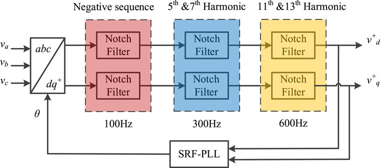
FIGURE 1. Principle of the notch-filtering method for extracting the positive sequence component.
2.2 DD-SRF-PLL
The structure of DD-SRF-PLL is shown in Figure 2. DD-SRF-PLL has a decomposition network for extracting the symmetrical components, which does not introduce any delay. However, a first-order low-pass filter with low cut-off frequency is required to stabilize the system. The harmonics can be filtered as a benefit but compromising on significant time delay. Due to the low attenuation rate, the harmonics actually will not be totally eliminated. The control system has to either endure the steady-state error or trade more dynamic responses for harmonic frequency by implementing more filters (Rodriguez, 2007).
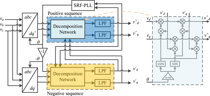
FIGURE 2. Diagram of DD-SRF-PLL for extracting the positive and negative sequence components.
2.3 Cascaded filtering method based on asynchronous coordinate transformation
A new method utilizing the characteristic of asynchronous coordinate transformation was recently reported. By reorganizing the coordinate transformation, a more optimized frequency heterodyne is achieved. Aided by the reduction in delay brought about by the utilization of the asynchronous coordinate transformation, the delay can be shorter than that of the other reported methods. Theoretically, the delay introduced can be infinitely small for removing one specific harmonic via the method presented in Hao (2018) if the frequency of the dq reference frame is infinitely large. However, the computational burden makes it impossible as the sampling rate should be high enough to avoid aliasing. In the method presented in Hao (2019), the three-phase signal is first transformed via a 200 Hz dq reference frame, where the negative sequence component is 250 Hz, while the fifth- and 13th-order harmonics became the ninth-order harmonic. Two half-cycle delay filters with delay of 2 ms and 1.1 ms remove these harmonics after the coordinate transformation. Then, the signals are transformed to a −100 Hz dq reference frame where both seventh- and 11th-order harmonic became the ninth-order harmonic and then filtered by a half-cycle delay filter. A diagram as shown in Figure 3 demonstrates the structure of this algorithm. This method balances the delay introduced and computational burden while achieving a smaller delay compared to the conventional methods. It is verified that the 10 kHz sampling rate would be sufficient for carrying out such an algorithm. However, it is also clear that the delay of each filter will add up as a main shortcoming. As the filters for different harmonics are connected in series, it is regarded as serial SCDs in this paper.
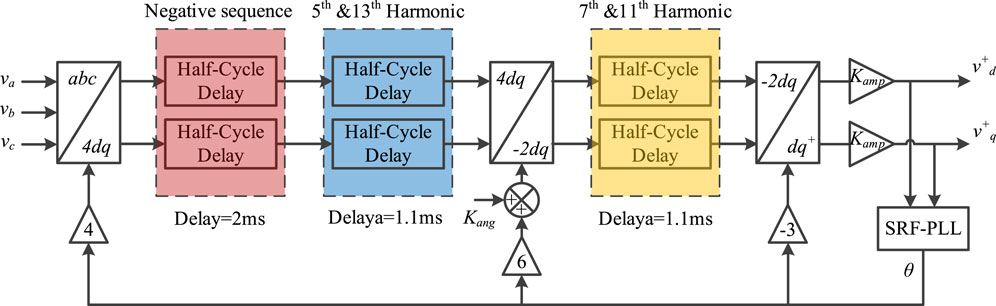
FIGURE 3. Diagram of the cascaded filtering method based on the asynchronous coordinate transformation.
3 Proposed parallel filtering scheme
Quite intuitively, if using only one asynchronous coordinate transformation to transfer the orders of the negative sequence component and low-order harmonics to have the same common divisor, then as shown in Figure 3, it could then be assumed that only one filter to get the positive sequence component, which may also shorten the total filter delay.
To verify the feasibility of the aforementioned assumption in theory, one set of equations as written in (1) is listed, where fi(n) are the harmonic order of the ith harmonic after the asynchronous coordinate transformation using n times fundamental frequency. A feasible n should conduct a result of fi(n) in one of the five equations to be the smallest, while others are odd multiples of the smallest one.
An exhaustive search algorithm is compiled to solve the problem. Several solutions are found. However, none of these solutions are feasible to serve the purpose of delay reduction. In conclusion, the aforementioned assumption is infeasible.
However, fortunately, the aforementioned assumption is feasible for directly extracting the negative sequence component, which can be verified by solving the equation set of (2), which is similar as (1).
Some solutions of (2) are found, among which n = −2 fulfills the requirement of delay reduction. Such characteristics give the opportunity to build a new filtering scheme to rapidly extract the positive sequence component.
Inspired by the parallel processing of popular control algorithms, the main idea of this paper is to construct a parallel filtering scheme, where one parallel branch directly extracts the negative sequence component with minimum delay, while the low-order harmonics are filtered in another parallel branch. Then, the extracted negative sequence component can be used to cancel the negative sequence component remaining in the output of the second branch so that the positive sequence components can be extracted. The whole time delay, therefore, depends on the larger one of the two branches. A diagram demonstrating the proposed algorithm is shown in Figure 4. The details are be elaborated in the following section.
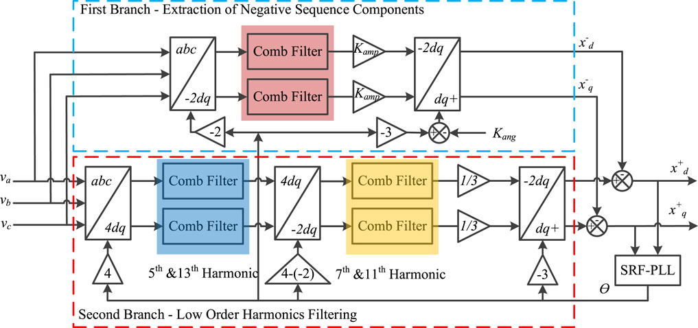
FIGURE 4. Proposed SCD scheme with parallel filtering structure.
3.1 Principle of asynchronous coordinate transformation
Before addressing the specific filtering configuration, the principle of asynchronous coordinate transformation will be comprehensively elaborated in this subsection to show how the asynchronous coordinate transformation works and how the orders of harmonics change under different coordinate frames, which indeed guide the transformation in the parallel filtering scheme.
In the conventional synchronous coordinate transformation scheme, the fundamental positive sequence components appear in the form of DC values, while other symmetrical components appear on the dq axis in an AC term, whose frequency equals the frequency of symmetrical components minus the frequency of the synchronous reference frame. This phenomenon is used in asynchronous coordinate transformation to increase the projected frequency of an unwanted symmetrical component so that when eliminating the unwanted signal, the delay can be reduced. The asynchronous coordinate transformation is realized the same as the conventional synchronous coordinate transformation, as addressed in (3). The only difference is that angle θ is generated by (4), where the angular speed ωn is a designed value, which is different from the fundamental angular speed ω, and n is a designed parameter defining the multiplier of the angular speed of the asynchronous reference frame regarding the synchronous reference frame.
In principle, the transformation between the asynchronous reference frame and synchronous reference frame is expandable to the generalized conversion between any two asynchronous reference frames with different frequencies. The frequencies of the two asynchronous reference frames are assumed as fn and fk, respectively, and expressed as (5).
where f is the fundamental frequency.
Then, transforming dq signals on the fn reference frame to fk reference frame can be performed via (6).
Another important characteristic of the asynchronous coordinate transformation is the frequency heterodyne. The frequency fi of a symmetrical component will become fi’ after asynchronous coordinate transformation, where i is the harmonic order and
All symmetrical components will suffer such kind of frequency shift. Consequently, the frequency distribution of symmetrical components changes. An example of frequency variation with n = 4 is demonstrated in Figure 5, where the previous fundamental component and seventh-order harmonic become the third-order component and the fifth-order and 13th-order harmonics both become the ninth-order harmonic in the new coordinate. This unique characteristic can help design the proper n in the parallel filtering scheme.
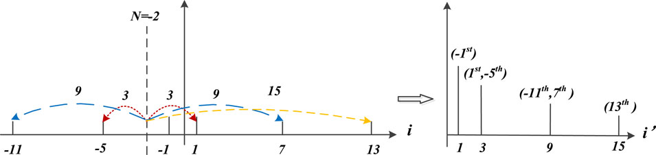
FIGURE 5. Characteristic of the asynchronous coordinate transformation and frequency heterodyne.
3.2 Negative sequence component extraction in the first branch
As shown in Figure 5, we can find that the fundamental component and fifth-order harmonic become the third-order harmonic by setting n = −2. Subsequently, the seventh-order harmonic and −11th-order harmonic both become the ninth-order harmonic, and the remaining 13th-order harmonic becomes the 15th-order harmonic. The aforementioned characteristic of frequency heterodyne is well consistent with the analysis of (2). So, one comb filter can filter out the transformed third-, ninth-, and 15th-order harmonics at the same time. It is worth mentioning that 4 is also a feasible n value to organize the unwanted harmonics in such an order. However, in that case, the negative sequence component will become the fifth-order harmonic which has a higher attenuation rate than that when n = −2, consequently lower signal-noise ratio in implementation. Thus n = 4 is not adopted.
In principle, for three-phase signals with harmonics distortion, the comb filter can eliminate a series of different frequency components by adding the real-time signal, and the signal delayed by a certain time interval [18]. A block diagram in Figure 6 demonstrates the structure of the comb filter. The frequencies of removed signals can be written as (8).
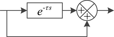
FIGURE 6. Structure of the comb filter.
where fe refers to the frequency of the removed component, n is a positive integer, and τ is the time delay of the comb filter. Therefore, to eliminate a series of harmonics with lowest frequency ft, τ should be set as
where ft refers to the lowest frequency of a series of harmonics to be eliminated. In this case, ft = 150 Hz, and then τ can be directly derived as 1/300 s.
Furthermore, the filtered signals are transformed to dq signals on the synchronous reference frame by setting n = −3, as shown in Figure 4. The negative sequence components can then be expressed as
where Kamp and Kang are the coefficients for compensating the amplitude and angle, respectively, whose values are determined by the coefficient n and the delay of the comb filter plus the delays of comb filters in the second branch, which will be completely derived in subsection D.
3.3 Low-order harmonic filtering in the second branch
The second branch shown in Figure 4 is designed to filter out the low-order harmonics, e.g., fifth-, seventh-, 11th-, and 13th- order harmonics. Its realization will be comprehensively elaborated in this subsection.
In particular, two stages of asynchronous coordinate transformation are applied, converting fifth- and 13th- order harmonics into the ninth-order harmonic in the first stage by setting n = 4 and seventh- and 11th- order harmonics into the ninth- order harmonic in the second stage by setting n = 6 since seventh- and 11th-order harmonics after the first stage transformation have become third- and 15th-order harmonics, respectively.
Comb filters tuned to remove the ninth-harmonic with the delay cost of 1/900 s are implemented in each stage to remove the unwanted harmonics.
It is obvious that filtering fifth-, seventh-, 11th-, and 13th- order harmonics will consume 1/450 s. In this case, the first branch will dominate the total filtering time delay. If other order harmonics should be further filtered, the similar procedure can be adopted.
3.4 Positive sequence component extraction
After the filtering operation of two branches, the next step is to add the fundamental negative sequence components extracted in the first branch to the remaining signal in the second branch so that the pure fundamental positive sequence components can be obtained.
But before that, the negative sequence components should be compensated properly, whose purpose is to tune the derived negative sequence component in the first branch equal to the remaining negative sequence component in the second branch. During signal processing, there are three comb filters employed in the two branches, all of which have impact on the amplitude and phase angle of the negative sequence components, respectively. Therefore, the compensation values of Kang and Kamp in (10) should be carefully derived by considering these impacts. Knowing that the frequency of the transformed signal is the difference between the frequency of the symmetrical component and that of the asynchronous coordinate transformation, the angle that should be compensated after one asynchronous coordinate transformation and the corresponding comb filter can be expressed as follows:
where fc is the frequency of the signal to be compensated, fn is the frequency of the asynchronous coordinate transformation, and τ is the time delay of the comb filter. Consequently, the compensation for the amplitude is
In the proposed method, the output of the low-order harmonic filter in the second branch contains both positive and negative sequence components, in which, negative sequence components are not compensated but falsely amplified. Therefore, to cancel the effect of the negative sequence components for obtaining pure positive sequence components, the compensation to the filtered signal in the first branch should be carried out not only to reconstruct the real negative sequence components but also taking the effect of the harmonic filtering in the second branch into consideration. The overall compensation for the angel and amplitude is
where Ang1 and Amp1 are the compensation coefficients for the filtering impact in the first branch and Ang2, Ang3, Amp2, and Amp3 are those for the filtering impact in the second branch. It is noted that the phase angle of fundamental positive sequence components will not be affected after three asynchronous coordinate transformations, and the amplitude of fundamental positive sequence components is compensated by multiplying 1/3, as shown in Figure 4.
Once again, the overall delay is 3.3 ms as the filtering of the low-order harmonics is processed in a loop parallel to the one for extracting the negative sequence components. The maximum delay is the same as the larger one of delays induced in the first or second branch.
After pre-filtering using the proposed scheme, the output dq signals only contains the fundamental positive sequence components, which would be in DC form. They can be used directly for driving an SRF-PLL to track the phase angle and frequency. The SRF-PLL adopted has a structure as shown in Figure 7. The dq signals are first unified so that the input to the PLL-control loop is between −1 and 1, depending only on angle error between the signal vector and the d-axis. This is for avoiding the dynamics of the PLL changes with the signal amplitude. A PI regulator is used in the SRF-PLL. At steady state in which the frequency of the signal is different from the feed-forward frequency denoting ɷff in Figure 7, the integrator will output a non-zero value to correct the error. This property is used for tracking the frequency.
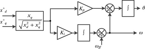
FIGURE 7. Structure of SRF-PLL.
In general, it is noted that as long as the derived symmetrical components could rapidly reach the accurate value after unbalanced and distorted operation, the control systems will benefit from this superior characteristic.
4 Simulation verification and experimental results
4.1 Simulation verification
The proposed SCD scheme is verified via simulation using MATLAB/Simulink. Meanwhile, comparisons to different methods are provided. The simulation results comparing the proposed method, the notch-filtering method, the DD-SRF-PLL, and cascaded delay method based on asynchronous coordinate transformation (referring to serial SCD) are presented. Figure 8 shows the simulation results under the single-phase voltage dip without harmonic distortion, where the performance of four different methods is clearly illustrated. Specifically, Figure 8A demonstrates the three-phase voltages without harmonic distortion, whose rated amplitude is 110×
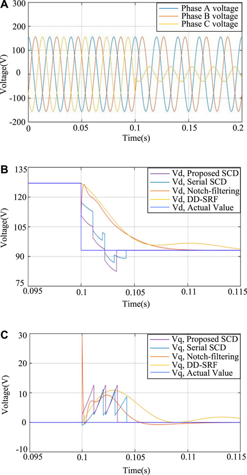
FIGURE 8. Simulation results of the SCD dealing with the single-phase voltage dip: (A) three-phase voltage, (B) extracted positive sequence Vd, and (C) extracted negative sequence Vq.
Then, to verify the feasibility of the proposed SCD processing a harmonic distorted and unbalanced three-phase signal, three sets of tests are carried out. First, the three-phase signals with harmonic distortion of fifth-, seventh-, 11th- and 13th-order harmonics are assumed. The amplitude of each harmonic listed previously is 5%, 4%, 3%, and 2% of the fundamental amplitude, respectively. The fundamental amplitude and frequency are 110×
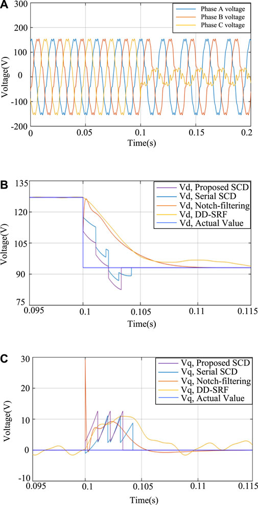
FIGURE 9. Simulation results of the SCD dealing with the single-phase voltage dip with typical low-order harmonics: (A) three-phase voltage, (B) extracted positive sequence Vd, and (C) extracted negative sequence Vq.
Second, when under heavy distortion conditions, the proposed method can still work well, which is verified by the simulation results shown in Figure 10, where the amplitude of fifth-, seventh-, 11th-, and 13th-order harmonics are increased to 10%, 7%, 5%, and 4% of the fundamental amplitude, respectively. It is noted from Figures 10B,C that the harmonic distortion will not affect the extraction of symmetrical components when using the proposed method. The proposed method can still rapidly and accurately extract the wanted positive and negative sequence components.
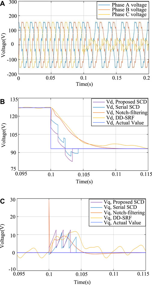
FIGURE 10. Simulation results of the SCD dealing with the single-phase voltage dip under heavy distortion conditions: (A) three-phase voltage, (B) extracted positive sequence Vd, and (C) extracted negative sequence Vq.
Third, a two-phase voltage dip is assumed in simulation, in which the fundamental frequency component is reduced to 40% of the nominal amplitude with the same harmonic content as in the previous verification, which would verify the harmonic rejection capability and the transient response against an unbalanced voltage dip and provide visual comparison. The simulated three-phase voltage waveforms are shown in Figure 11A, where harmonic distortion and voltage dip are both simulated. As observed from Figure 11B and C, it is concluded that the proposed method can deal with various unbalanced voltage conditions with promising performance. The positive sequence component can still be accurately extracted after 3.3 ms if grid faults occur.
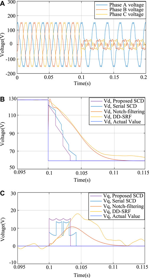
FIGURE 11. Simulation results of the SCD dealing with the two-phase voltage dip with typical low-order harmonics: (A) three-phase voltage, (B) extracted positive sequence Vd, and (C) extracted negative sequence Vq.
4.2 Experimental verification
The experimental test was also carried out. dSPACE MicroLabBox was adopted to carry out signal processing with the sampling frequency of 20 kHz. About 110 V distorted three-phase voltages are provided by the AMETEK Ls4500 ac voltage source. The voltage transducers are used to convert 110 V ac voltage to a safe range for the input of the dSPACE. The LeCroy 8-channel oscilloscope captures and records the waveforms of the three-phase voltages and the estimated dq signals were sent out by D/A channels of dSPACE. The three-phase voltages will go through three steady states and two transient moments in between. The steady-state response and the transient response of the proposed algorithm are tested. At the beginning, the balanced three-phase voltages of 110 V/50 Hz are provided without any harmonic distortion, during which the steady state of the algorithm under healthy grid conditions is demonstrated. Then, the fundamental voltage of Phase A is decreased to 30 V. At the same time, fifth-, seventh-, 11th-, and 13th-order harmonics with amplitudes of 10%, 7%, 5%, and 4% of 110 V, respectively, are added. In this stage, the transient response of the algorithm due to a sudden change in the fundamental positive and negative sequence components as well as a step input of the harmonics are shown. The three-phase voltages are unbalanced and distorted for the next two fundamental cycles during which the steady-state output will be available for examining any steady-state error. Then, Phase A voltage is back to 110 V, but the harmonic distortion remains unchanged. The three design experiment stages would verify the performance of the proposed method working under normal condition, distorted and unbalanced three-phase voltages, and distorted three-phase voltages, as well as the transient response between these conditions.
Figure 12 shows the experimental results including the clear comparison between the conventional methods and the proposed method. During the first transient stage where the grid voltage started to be unbalanced and distorted, while the output of the proposed method tracked the variation of the symmetrical components, two small transients are visible in the output signal, as shown in the waveforms of Figure 12A, B, and C. These transients are caused by two comb filters adopted in the harmonic filtering branch. In all experimental results presented, the total transient interval of the proposed SCD method is 3.3 ms, which is the size of the transient interval of the negative sequence extraction branch. The extraction speed is consistent with the simulation results.
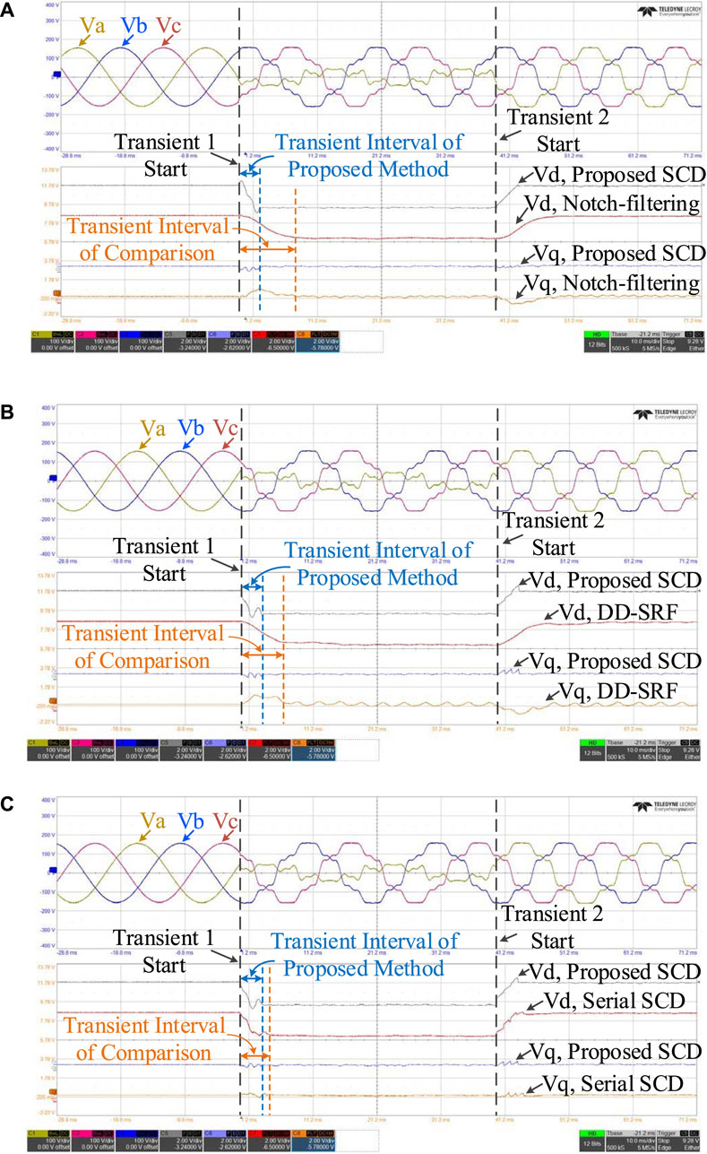
FIGURE 12. Experimental results of the proposed method with comparison to the (A) notch-filtering method, (B) DD-SRF-PLL method, and (C) serial SCD method.
The transient interval of the proposed SCD is clearly smaller than that of the widely used conventional methods. The extracted positive and negative sequence components of the proposed SCD method are in a harmonic-free dc form. In contrast, there is visible oscillation in the negative sequence output of the notch-filtering method, as shown in Figure 12A. This oscillation is due to low sampling frequency. There is also a visible oscillation in the output of the DD-SRF-PLL in Figure 12B because the first-order low-pass filters, originally designed to stabilize the system, are used to attenuate the harmonics whose cut-off frequency is too close to the oscillation frequency, leading to the phenomenon that the harmonics cannot be perfectly removed. Finally, comparing to the cascading filtering method using asynchronous coordinate transformation, as shown in Figure 12C, the proposed method is faster, the same as analyzed in theory.
5 Conclusion
This paper proposes a new method for rapidly extracting the fundamental positive sequence component from the distorted and unbalanced three-phase voltages. Being different from the existing methods, the proposed method specifically assumes two parallel branches to shorten the delay time, where the asynchronous coordinate transformation and comb filter for removing the selected harmonic components are employed. Specifically, the optimized asynchronous coordinate transformation considering the typical distorted grid voltage was established. Via the designed asynchronized coordinate transformation, the extraction of negative sequence components can be easily achieved with the minimum delay introduced. Furthermore, the parallel filtering scheme is thus made possible for further reducing the extraction delay of positive sequence component. From the simulation and experimental results, the transient interval of the proposed method is smaller than that of the compared counterparts. The transient interval of the proposed method is 3.3 ms, which is consistent with that predicted by theoretical analysis.
Data availability statement
The original contributions presented in the study are included in the article/Supplementary Material; further inquiries can be directed to the corresponding author.
Author contributions
Conceptualization, writing, and original draft preparation: TH; validation: SH; writing—review and editing: GY. All authors contributed to the article and approved the submitted version.
Funding
This research was funded by the National Natural Science Foundation of China, grant number 51907107.
Conflict of interest
The authors declare that the research was conducted in the absence of any commercial or financial relationships that could be construed as a potential conflict of interest.
Publisher’s note
All claims expressed in this article are solely those of the authors and do not necessarily represent those of their affiliated organizations, or those of the publisher, the editors, and the reviewers. Any product that may be evaluated in this article, or claim that may be made by its manufacturer, is not guaranteed or endorsed by the publisher.
References
Arrillaga, J., Watson, N. R., and Murray, N. J., and (1996). Modeling and simulation of the propagation of harmonics in electric power networks I Concepts, models, and simulation techniques. IEEE Trans. Power Deliv. 11 (1), 452–465. doi:10.1109/61.484130
Avdiaj, E. B., D’Arco, S., Piegari, L., and Suul, J. A. (2022). Negative sequence control for virtual synchronous machines under unbalanced conditions. IEEE J. Emerg. Sel. Top. Power Electron. 10 (5), 5670–5685. doi:10.1109/jestpe.2022.3175169
Badoni, M., Singh, A., Pandey, S., and Singh, B. P. (2022). Fractional-order notch filter for grid-connected solar PV system with power quality improvement. Trans. Industrial Electron. 69 (1), 429–439. doi:10.1109/tie.2021.3051585
Bamigbade, A., and Khadkikar, V. P. (2022). A cascaded integral action based filter for distorted conditions. IEEE Trans. Industrial Electron. 69 (10), 10752–10760. doi:10.1109/tie.2022.3161793
Baradarani, F., Dadash Zadeh, M. R., and Zamani, M. A. (2015). A phase-angle estimation method for synchronization of grid-connected power-electronic converters. IEEE Trans. Power Deliv. 30 (2), 827–835. doi:10.1109/tpwrd.2014.2362930
Du, W., Chen, X., and Wang, H. P. (2017). PLL-induced modal resonance of grid-connected PMSGs with the power system electromechanical oscillation modes. IEEE Trans. Sustain. Energy 8 (4), 1581–1591. doi:10.1109/tste.2017.2695563
Ge, J., Shuai, Z., Tu, C., Luo, A., and Shen, Z. J. (2021). Flexible control strategy for enhancing power injection capability of three-phase four-wire inverter during asymmetrical grid faults. IEEE Trans. Power Electron. 36 (8), 9592–9608. doi:10.1109/tpel.2021.3054827
Golestan, S., Mousazadeh, S. Y., Guerrero, J. M., and Vasquez, J. C. (2017). A critical examination of frequency-fixed second-order generalized integrator-based phase-locked loops. IEEE Trans. Power Electron. 32 (9), 6666–6672. doi:10.1109/tpel.2017.2674973
Golestan, S., Ramezani, M., Guerrero, J. M., and Monfared, M. (2015). Frame cascaded delayed signal cancellation- based PLL: Analysis, design, and comparison with moving average filter-based PLL. IEEE Trans. Power Electron. 30 (3), 1618–1632. doi:10.1109/tpel.2014.2315872
Gonzalez-Espin, F., Figueres, E., and Garcera, G. P. (2012). An adaptive synchronous-reference-frame phase-locked loop for power quality improvement in a polluted utility grid. IEEE Trans. Industrial Electron. 59 (6), 2718–2731. doi:10.1109/tie.2011.2166236
Guo, X. Q., Liu, W. Z., and Lu, Z. G. (2017). Flexible power regulation and current-limited control of the grid-connected inverter under unbalanced grid voltage faults. IEEE Trans. Industrial Electron. 64 (9), 7425–7432. doi:10.1109/tie.2017.2669018
Guo, X., Zhang, X., Wang, B., Wu, W., and Guerrero, J. M. (2014). Asymmetrical grid fault ride-through strategy of three-phase grid-connected inverter considering network impedance impact in low-voltage grid. IEEE Trans. Power Electron. 29 (3), 1064–1068. doi:10.1109/tpel.2013.2278030
Hackl, C. M., and Landerer, M., P. (2020). Modified second-order generalized integrators with modified frequency locked loop for fast harmonics estimation of distorted single-phase signals. IEEE Trans. Power Electron. 35 (3), 3298–3309. doi:10.1109/tpel.2019.2932790
Han, Y., Luo, M., Zhao, X., Guerrero, J. M., and Xu, L. (2016). Comparative performance evaluation of orthogonal-signal-generators-based single-phase PLL algorithms—a survey. IEEE Trans. Power Electron. 31 (5), 3932–3944. doi:10.1109/tpel.2015.2466631
Hao, T., Gao, F., and Xu, T. P. (2019). Fast extraction of symmetrical components from distorted three-phase signals based on asynchronous-rotational reference frame. J. Power Electron. 19 (4), 1045–1053. doi:10.1109/TPEL.2018.2822941
Hao, T., Gao, F., and Xu, T. P. (2018). Fast symmetrical component extraction from unbalanced three phase signals using non-nominal DQ transformation. IEEE Trans. Power Electron. 33 (11), 9134–9141. doi:10.1109/tpel.2018.2822941
Hoepfner, B., and Vick, R. (2023). A three-phase frequency-fixed DSOGI-PLL with low computational effort. IEEE Access 11, 34932–34941. doi:10.1109/access.2023.3265299
Hu, Q., Fu, L., Ma, F., Ji, F., and Zhang, Y. (2021). Analogized synchronous-generator model of PLL-based VSC and transient synchronizing stability of converter dominated power system. IEEE Trans. Sustain. Energy 12 (2), 1174–1185. doi:10.1109/tste.2020.3037155
Huang, Q., and Rajashekara, K. P. (2017). An improved delayed signal cancellation PLL for fast grid synchronization under distorted and unbalanced grid condition. IEEE Trans. Industry Appl. 53 (5), 4985–4997. doi:10.1109/tia.2017.2700282
Jain, P., Agarwal, V., and Muni, B. P. (2018). Hybrid phase locked loop for controlling master-slave configured centralized inverters in large solar photovoltaic power plants. IEEE Trans. Industry Appl. 54 (4), 3566–3574. doi:10.1109/tia.2018.2808342
Khalid, H. M., Muyeen, S., and Kamwa, I. (2022). An improved decentralized finite-time approach for excitation control of multi-area power systems. Sustain. Energy, Grids Netw. 31, 1–13. 100692. doi:10.1016/j.segan.2022.100692
Lee, K. J., Lee, J. P., Shin, D., Yoo, D. W., and Kim, H. J. (2014). A novel grid synchronization PLL method based on adaptive low-pass notch filter for grid-connected PCS. IEEE Trans. Industrial Electron. 61 (1), 292–301. doi:10.1109/tie.2013.2245622
Liu, X., Wu, B., and Xiu, L., P. (2022). A fast positive-sequence component extraction method with multiple disturbances in unbalanced conditions. IEEE Trans. Power Electron. 37 (8), 8820–8824. doi:10.1109/tpel.2022.3161734
Montero-Robina, P., Rouzbehi, K., Gordillo, F., and Pou, J. P. (2021). Grid-following voltage source converters: Basic schemes and current control techniques to operate with unbalanced voltage conditions. IEEE Open J. Industrial Electron. Soc. 2, 528–544. doi:10.1109/ojies.2021.3121764
Ng, C. H., Ran, L., and Bumby, J. (2008). Unbalanced-grid-fault ride-through control for a wind turbine inverter. IEEE Trans. Industry Appl. 44 (3), 845–856. doi:10.1109/tia.2008.921429
Rafique, Z., Khalid, H. M., Muyeen, S., and Kamwa, I. (2022). Bibliographic review on power system oscillations damping: An era of conventional grids and renewable Energy integration. Int. J. Electr. Power Energy Syst. 136, 1–20. 107556. doi:10.1016/j.ijepes.2021.107556
Reyes, M., Rodriguez, P., Vazquez, S., Luna, A., Teodorescu, R., and Carrasco, J. M. (2012). Enhanced decoupled double synchronous reference frame current controller for unbalanced grid-voltage conditions. IEEE Trans. Power Electron. 27 (9), 3934–3943. doi:10.1109/tpel.2012.2190147
Rodriguez, P., Pou, J., Bergas, J., Candela, J. I., Burgos, R. P., and Boroyevich, D. (2007). Decoupled double synchronous reference frame PLL for power converters control. IEEE Trans. Power Electron. 22 (2), 584–592. doi:10.1109/tpel.2006.890000
Shangguan, X. C., Zhang, C. K., He, Y., Jin, L., Jiang, L., Spencer, J. W., et al. (2021). Robust load frequency control for power system considering transmission delay and sampling period. IEEE Trans. Industrial Inf. 17 (8), 5292–5303. doi:10.1109/tii.2020.3026336
Shin, D., Lee, K. J., Lee, J. P., Yoo, D. W., and Kim, H. J. (2015). Implementation of fault ride-through techniques of grid-connected inverter for distributed Energy resources with adaptive low-pass notch PLL. IEEE Trans. Power Electron. 30 (5), 2859–2871. doi:10.1109/tpel.2014.2378792
Shuai, Z., Xiao, M., Ge, J., and Shen, Z. J. (2019). Overcurrent and its restraining method of PQ-controlled three-phase four-wire converter under asymmetrical grid fault. IEEE J. Emerg. Sel. Top. Power Electron. 7 (3), 2057–2069. doi:10.1109/jestpe.2018.2885553
Taul, M. G., Wang, X., Davari, P., and Blaabjerg, F. (2020). Current reference generation based on next-generation grid code requirements of grid-tied converters during asymmetrical faults. IEEE J. Emerg. Sel. Top. Power Electron. 8 (4), 3784–3797. doi:10.1109/jestpe.2019.2931726
Wang, G., Wang, X., and Lv, J., P. (2020). An improved harmonic suppression control strategy for the hybrid microgrid bidirectional AC/DC converter. IEEE Access 8, 220422–220436. doi:10.1109/access.2020.3042572
Wang, Y. F., and Li, Y. W. (2013). Three-phase cascaded delayed signal cancellation PLL for fast selective harmonic detection. IEEE Trans. Industrial Electron. 60 (4), 1452–1463. doi:10.1109/tie.2011.2162715
Xin, Z., Wang, X., Qin, Z., Lu, M., Loh, P. C., and Blaabjerg, F. (2016). An improved second-order generalized integrator based quadrature signal generator. IEEE Trans. Power Electron. 31 (12), 8068–8073. doi:10.1109/tpel.2016.2576644
Yazdani, D., Bakhshai, A., Joos, G., and Mojiri, M. (2008). A nonlinear adaptive synchronization technique for grid-connected distributed Energy sources. IEEE Trans. Power Electron. 23 (4), 2181–2186. doi:10.1109/tpel.2008.926045
Yazdani, D., Mojiri, M., Bakhshai, A., and Joos, G. (2009). A fast and accurate synchronization technique for extraction of symmetrical components. IEEE Trans. Power Electron. 24 (3), 674–684. doi:10.1109/tpel.2008.2010321
Yin, G., Guo, L., and Li, X. P. (2013). An amplitude adaptive notch filter for grid signal processing. IEEE Trans. Power Electron. 28 (6), 2638–2641. doi:10.1109/tpel.2012.2226752
Zhang, X., Xia, D., Fu, Z., Wang, G., and Xu, D. (2018). An improved feedforward control method considering PLL dynamics to improve weak grid stability of grid-connected inverters. IEEE Trans. Industry Appl. 54 (5), 5143–5151. doi:10.1109/tia.2018.2811718
Zhao, X., Guerrero, J. M., Savaghebi, M., Vasquez, J. C., Wu, X., and Sun, K. (2018). Low-voltage ride-through operation of power converters in grid-interactive microgrids by using negative-sequence droop control. IEEE Trans. Power Electron. 32 (4), 3128–3142. doi:10.1109/tpel.2016.2570204
Appendix
The proposed SCD, as shown in Figure 4, can be concluded by the pseudocode listed in the following section, where the main data stream, negative sequence data stream and harmonic filtering stream are listed in Tables A1–A3, respectively.
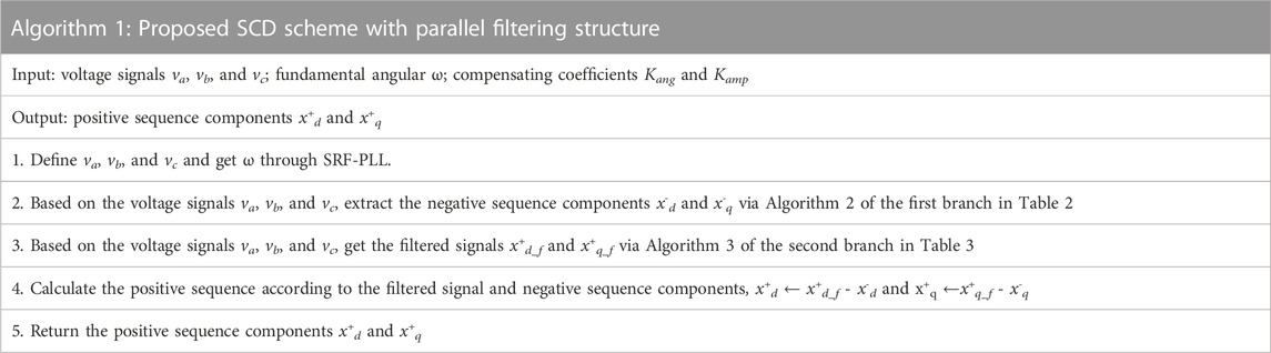
TABLE A1. Pseudocode of the proposed scheme.
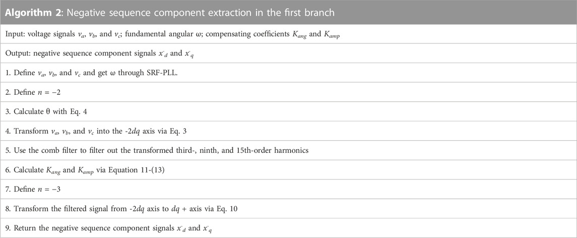
TABLE A2. Pseudo code of the first branch.
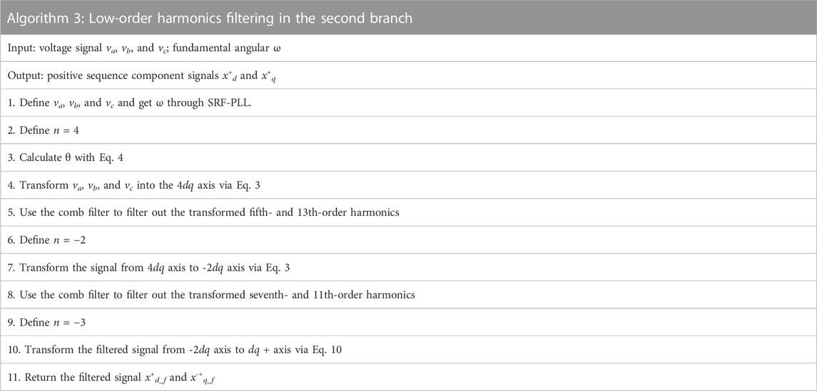
TABLE A3. Pseudocode of the second branch.
Keywords: symmetrical component, asynchronous coordinate transformation, distorted three-phase signals, parallel filtering, phase-locked loop
Citation: Hao T, Han S and Yan G (2023) Parallel filtering scheme for fast symmetrical component extraction based on asynchronous coordinate transformation. Front. Energy Res. 11:1206248. doi: 10.3389/fenrg.2023.1206248
Received: 17 April 2023; Accepted: 14 June 2023;
Published: 28 June 2023.
Edited by:
Haris M. Khalid, Higher Colleges of Technology, United Arab EmiratesCopyright © 2023 Hao, Han and Yan. This is an open-access article distributed under the terms of the Creative Commons Attribution License (CC BY). The use, distribution or reproduction in other forums is permitted, provided the original author(s) and the copyright owner(s) are credited and that the original publication in this journal is cited, in accordance with accepted academic practice. No use, distribution or reproduction is permitted which does not comply with these terms.
*Correspondence: Tianqu Hao, aGFvdGlhbnF1QHNkdS5lZHUuY24=