 Jiansong Li
 Shaohui Li1
94% of researchers rate our articles as excellent or good
Learn more about the work of our research integrity team to safeguard the quality of each article we publish.
Find out more
ORIGINAL RESEARCH article
Front. Energy Res. , 12 June 2023
Sec. Process and Energy Systems Engineering
Volume 11 - 2023 | https://doi.org/10.3389/fenrg.2023.1202914
This article is part of the Research Topic Optimal Design and Efficiency Improvement of Fluid Machinery and Systems View all 18 articles
The global energy crisis and growing environmental concerns provide a strong impetus for the development of fuel-efficient hydraulic excavators (HEs). The boom potential energy of a conventional HE is consumed by throttling in a lowering process, which is a major reason for energy inefficiency. To solve the issue, this paper presents a flywheel-based boom energy regeneration system for HEs using load-sensing systems. The otherwise wasted boom potential energy is regenerated by a pump/motor and stored in a flywheel. The recaptured energy is reused in the form of pressure energy released to the pump outlet. The energy efficiencies of a conventional load-sensing system and the proposed system were analyzed. A control strategy was proposed to optimize the energy-saving procedure. To obtain a more reliable simulation model, a coasting experiment of the flywheel was carried out to obtain the key parameters related to the friction of the flywheel. A 4-t HE in our laboratory was selected as a study case to investigate the energy-saving effect of the flywheel-based boom energy regeneration system. Numeric simulations showed that compared with a conventional load-sensing system, the energy-saving rate was about 32.7% in a typical digging and dumping cycle. These findings indicated that the flywheel-based boom energy regeneration system is promising for developing energy-efficient HEs.
The global energy crisis and growing environmental concerns provide a strong impetus for the development of fuel-efficient construction machinery. This task is particularly of great importance in the case of hydraulic excavators (HEs) because HEs are the most widely used construction machinery in engineering construction. Conventional HEs frequently move up and down heavy booms to complete related work. During the lowering of the boom, the gravitational potential energy is converted into heat energy, which will cause the oil temperature to increase. This not only leads to energy waste but also increases the fluid temperature and shortens the life of the hydraulic components. The boom gravitational potential energy reportedly accounts for 15% of the total output energy of the diesel engine for a typical medium-size HE (Triet and Ahn, 2011). Therefore, studying how to recover and reuse the boom gravitational potential energy is of great significance for improving the energy efficiency of HEs and reducing the discharge of pollutants. Adding an energy regeneration system (ERS) is an effective energy-saving approach. According to the form of recaptured energy, ERSs can be classified into three major categories: electric, hydraulic, and mechanical systems (Yu and Ahn, 2019).
Inspired by the technology used in the automotive industry, electric ERSs were first developed in the field of HEs. Electric ERSs adopt a hydraulic motor and a generator as an energy converter (Wang and Wang, 2014) and either a battery or an ultracapacitor as the energy storage device (Hussaini and Wang, 2022). The battery has the advantage of high energy density while the ultracapacitor has the characteristic of high specific power. Wang et al. (Lin et al., 2010) proposed a pressure-compensated ERS with a hydraulic motor and generator installed in the main return line. The corresponding tests showed that up to 60% of the potential energy could be recovered. The recovered energy could be reutilized by adding another motor to assist the engine (Xia et al., 2019). Compared with traditional HEs that use internal combustion engines as a power source, the electric ERS is preferable for electric excavators because the existing batteries will greatly reduce the manufacturing investment (Amirante et al., 2017). However, excessive energy conversion cycles in electric ERSs can lead to a decrease in energy utilization efficiency. The low specific power and cycle life of batteries (Wang et al., 2017) are barriers to the mass application of this technology. Although ultracapacitors have the advantage of high specific power and lifetime, their high manufacturing cost and low specific energy are disadvantages (Joo and Stangl, 2016).
Hydraulic ERSs use hydraulic accumulators as energy storage devices. Such systems are characterized by high specific power and low manufacturing costs. Considering the existing hydraulic system in HEs, fewer energy conversions are involved in the hydraulic ERS than others. Regarding energy reutilization, the recaptured energy either can be used to assist the engine when high power is required (Zhao et al., 2011); releasing the pressurized fluid to the pump suction port (Ho and Ahn, 2008; Casoli et al., 2016) is another choice to reutilize the recaptured energy. However, the pressure in the hydraulic accumulator changes dramatically in the energy recovery and release process. This character will impact the boom movement during the lowering process and lead to inefficiency and difficulty in reusing the recaptured energy when the pressure in the accumulator is low. This is the so-called “pressure coupling” issue. To solve this problem, hydraulic transformers (Bui et al., 2015; Ge et al., 2018) and asymmetric pumps (Wasbari et al., 2017) have been developed. However, both of the above are in the research stage and no commercial products are currently available. Another issue is that hydraulic accumulators require more installation space and tend to be bulky due to the low specific energy (Takahashi et al., 2002).
Mechanical ERSs using flywheels have the potential for use in a range of applications due to their many advantages. High-speed flywheels have a high specific energy of up to 200 Wh/kg (Hedlund et al., 2015). Compared with batteries, an almost unlimited service life (in the order of 107 cycles) is the most important advantage (Hadjipaschalis et al., 2009). Furthermore, the energy storage capacity of a flywheel is independent of time or discharge depth. Flywheels also have disadvantages. One distinguishing disadvantage of the flywheel-based ERS is the high self-discharge rate (Zhou et al., 2013). For long-term applications, this feature will lead to unacceptable energy loss. However, if a flywheel is used as a buffer, the energy loss could be negligible (Dhand and Pullen, 2015). Many studies have explored the energy-saving potential of mechanical ERSs in the vehicle field (Li and Zhao, 2021), but very few have focused on HEs. We previously analyzed the main advantages of a flywheel-based architecture and discussed the feasibility of using a flywheel-based energy recovery system to regenerate the boom potential energy (Li et al., 2020). Specifically, we introduced a flywheel-based ERS for HE (Mahato and Ghoshal, 2020) and investigated the energy recovery effect. However, that study did not discuss the interaction of the original system and the added ERS. For HEs with different hydraulic architecture, the energy-saving effect should differ, even when adopting the same ERSs.
Load-sensing systems are commonly used in HEs (Xu et al., 2017). In this paper, an energy-saving system composed of a load-sensing system and a flywheel-based ERS is analyzed and the energy-saving effect is discussed. The remainder of this paper is structured as follows. Section 2 describes and analyzes the newly proposed system configuration and working principles. Section 3 presents and analyzes the energy analysis methodology. Section 4 describes the control strategy. The coasting experiment of the flywheel is shown in Section 5. The simulation model is built in AMESim software and corresponding simulations are studied in Section 6. Finally, conclusions are drawn in Section 7.
A conventional load-sensing system of a HE boom subsystem is shown in Figure 1 (left half). This hydraulic system is composed of a pump, a main valve, and a boom cylinder. The pump is load-sensing and can automatically adjust its displacement to exactly deliver flow as required by the main valve and keep the pressure above the load pressure by a preset value. The main valve is an electronic proportional valve. Two check valves and two secondary relief valves are used to set the maximum feedback pressure in the corresponding pipes. When the boom lowers, due to the boom gravity, the pump just provides low-pressure fluid to the rod side of the boom cylinder.
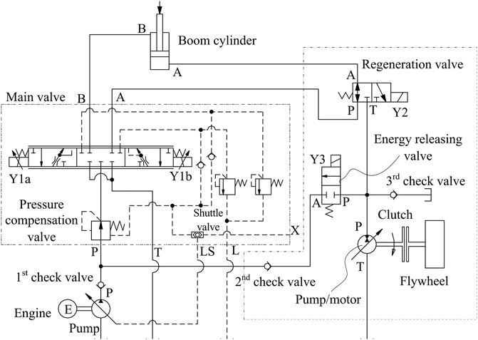
FIGURE 1. Proposed load-sensing system with a flywheel-based energy regeneration system.
Figure 1 shows the proposed load-sensing system with a flywheel-based ERS (LS-FERS). Compared with the original system, a flywheel-based ERS is added to regenerate and reutilize the potential energy of the boom. The flywheel-based ERS consists of a hydraulic pump/motor (PM), a clutch, a flywheel, a regeneration valve, an energy-releasing valve, and three check valves. The PM is the energy converter and the flywheel is the energy storage device. The swashplate of the PM can swing to a negative angle or a positive angle, so the PM can reverse its flow direction without auxiliary valves and switch its operation mode. The clutch is energized to connect the shafts of the PM and the flywheel when there is an energy exchange between them. If not, the clutch is de-energized to avoid unnecessary friction loss. The regeneration valve is employed to control the operation of the flywheel-based ERS. The energy-releasing valve is activated when the ERS releases energy to the original system. The first and second check valves block any reverse fluid. The third check valve is employed to connect the inlet of the PM and the reservoir to avoid cavitation (Kan et al., 2022). The recaptured energy will be reutilized by releasing pressurized fluid to the inlet of the main valve.
The three modes for the ERS are the regeneration mode, the reutilization mode, and the standby mode. The operation principle of the proposed system is as follows:
(1) Regeneration mode. When the boom cylinder is lowered through the gravity force of the working device, the fluid discharged by the pump goes into the rod side of the boom cylinder. The regeneration valve shifts to its right position, and the fluid discharged from the cap side of the boom cylinder goes through the regeneration valve and the PM into the reservoir. The PM works in motoring mode and the pressure energy is converted into mechanical energy to accelerate the flywheel. As the name implies, the potential energy is regenerated and stored in the flywheel in the form of kinetic energy.
(2) Reutilization mode. When the boom is to be driven upwards, the fluid provided by the pump is directed by the main valve to the cap side of the boom cylinder. At the same time, the energy-releasing valve and the clutch are energized. The flywheel drives the PM at the cost of decreasing its rotational speed and the PM works in pumping mode. The fluid output from port P of the PM flows through the energy-releasing valve and the second check valve and joins the pump flow at the inlet of the main valve. Thus, the recaptured energy is used to drive the boom cylinder.
(3) Standby mode. When the boom is held in a certain position, the system enters the standby mode. In this mode, all valves return to their original positions and the clutch is de-energized. The flywheel remains rotating but its speed gradually decreases due to inevitable friction.
From the aforementioned description, it can be concluded that the LS-FERS consumes less energy than the conventional load-sensing system.
To better understand the energy distribution characteristics of the LS-FERS, the energy flow was compared between the original system and LS-FERS. The energy-saving effect of the LS-FERS was also analyzed. First, some assumptions were made.
• The tank pressure was always zero;
• The energy consumption caused by the pump control device was included in the energy loss of the pump;
• The dynamic of the clutch was negligible because a typical response time of an electromagnetic clutch was of the same order as that of an electromagnetic valve;
• The energy consumption of the pilot circuit was negligible;
• The energy losses of all check valves were negligible;
• The energy losses caused by the slippage of the clutch were negligible; and
• The internal and external leakages of the boom cylinder were negligible.
For the original system, the mechanical energy absorbed by the pump was given as follows:
where Tp is the driving torque and np is the rotational speed of the pump.
The pressure energy output by the pump is described by
where pp is the pressure and qp is the flow rate at the pump outlet.
Hence, the energy loss of the pump is
The energy delivered to the boom cylinder is given by
where pcyliner_in and qcylinder_in represent the pressure and the flow rate at the boom cylinder inlet, respectively.
Since there is no flow loss at the main valve, the meter-in energy loss of the main valve is the throttling loss between the pump outlet and the boom cylinder inlet, which can be described by
In a load-sensing hydraulic system, the pressure difference between the pump outlet and the actuator (the boom cylinder inlet) should equal the setting pressure difference of the pump, which is
In a complete boom operation cycle, the energy equilibrium of the boom cylinder is
where Ecylinder_out is the output energy at the boom cylinder outlet and ΔEcylinder is the energy loss at the boom cylinder. The output energy can be expressed as
No matter whether the boom cylinder extends or retracts, the output energy of the boom cylinder is consumed at the main valve. This is the meter-out energy loss of the main valve,
The total energy losses at the main valve can be calculated by
The inlet and outlet of the boom cylinder vary according to specific working conditions. When the boom is lifted, the pump flow enters the cap side chamber of the boom cylinder. That is,
When the boom is lowered, the pump flow enters the rod side chamber of the boom cylinder. That is,
where p1 and q1 are the pressure and flow rate of the cap side chamber of the boom cylinder and p2 and q2 are the pressure and flow rate of the rod side chamber of the boom cylinder, respectively.
According to Newton’s Second Law, the force balance equation of the boom cylinder is as follows:
where Acap and Arod represent the area of the cap side and the rod side of the boom cylinder, respectively; m is the equivalent mass of the working device; x is the piston displacement; B is the viscous friction coefficient, Fcylinder is the coulomb friction force; and FBoom is the output force of the boom cylinder.
The energy losses of the boom cylinder are caused by the coulomb friction force and the viscous friction forces. So,
According to the aforementioned equations, the energy efficiency from the engine to the boom can be described as
The energy flow and losses of the LS-FERS can also be described by the aforementioned equations but based on the boom cylinder. The recoverable energy is the pressure energy output from the cap side chamber of the boom cylinder during lowering, while the energy output of the boom lifting process is not included, which can be concluded from the operation principle in Section 2. Therefore, the recoverable energy is as follows:
where t3 and t4 are the start and end times of the boom-lowering process, respectively.
The regenerated energy Er is the kinetic energy of the flywheel, which can be written as
where J is the moment of inertia of the flywheel and ωf_max is the rotational speed just after the regeneration process is completed.
The ratio of the boom potential energy regeneration of the proposed system is calculated as follows:
As illustrated in Section 2, during the lifting process, the flywheel drives the PM to provide pressurized fluid. So, in a complete boom operation cycle, the energy-saving rate of the proposed system can be described as
where
From the aforementioned analysis, one can conclude that the more energy the pump motor provides to the system, the less energy the hydraulic pump provides, and the better the energy-saving effects achieved by the system. To achieve the aforementioned goals, appropriate control strategies are required to improve the energy efficiency of the pump motor.
The two problems to be solved by the control strategy are how to regenerate the potential energy as much as possible and how to efficiently release the recaptured energy. When the boom goes down, the boom speed is regulated by adjusting the displacement of the PM. At the same time, the boom potential energy is converted to the kinetic energy of the flywheel. When the boom is lifted, the PM provides part of the fluid needed by the system to reduce the energy required by the engine. However, to efficiently use the recaptured energy, considering that the total efficiency of the PM is low when operating in a small displacement (Gong et al., 2019), only when the control signal of boom-up (Iup) is greater than its half-maximum value (Iup_max) can the PM provide fluid to the main valve. The control strategy is described in Figure 2.
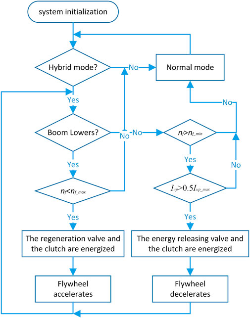
FIGURE 2. Flow chart of the control strategy.
The flywheel coasting experiment refers to the experimental process in which there is no energy exchange between the flywheel and the hydraulic motor, the flywheel rotates due to its own inertia, and its rotational speed gradually decreases because of air resistance and bearing friction. Since the current design used a low-speed metal flywheel with common deep groove ball bearings, the friction should not be ignored, especially when the flywheel is running in the atmospheric environment. For this reason, the self-discharging characteristics of the flywheel were tested. Figure 3 shows the coasting state of the flywheel used in the flywheel-based energy regeneration system. The relationship between the flywheel’s rotational speed and time is also shown in Figure 3. In this figure, when the clutch is disconnected, the flywheel speed gradually decreases. At initial speeds of 500, 750, and 1,000 rev/min respectively, the flywheel requires approximately 200, 330, and 400 s from its initial state to stop. At the three initial speeds, it required approximately 8, 13, and 15 s to reduce the flywheel speed by 10% from the initial speed. These times are much longer than those for the boom lifting and landing cycle of the normal excavator, and more than the dwell time between boom lifting and landing actions during normal operation (about 1–2 s). These results showed that the energy loss of the flywheel itself could be ignored. In conclusion, the flywheel system had good self-discharging performance and could meet the requirements of the subsequent experiments.
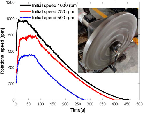
FIGURE 3. Flywheel rotational speed in terms of time.
According to the experimental data, the speed curve of the flywheel under the coasting state was fitted, as shown in Figure 4. At the same time, based on these data, the relevant resistance parameters of the flywheel model were obtained, which were used for the following simulation. Figure 4 shows the speed curve of the flywheel model used for simulation under the self-energized state. Furthermore, the error was very small during most speed intervals, especially in the high-speed section. The figure demonstrates the high similarity of the simulation curve with the experimental data.
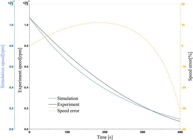
FIGURE 4. Experiment speed, simulation speed, and flywheel error in the coasting mode.
To verify the energy regeneration and reutilization efficiency of the LS-FERS, Figure 5 shows a simulation model established in Amesim software.
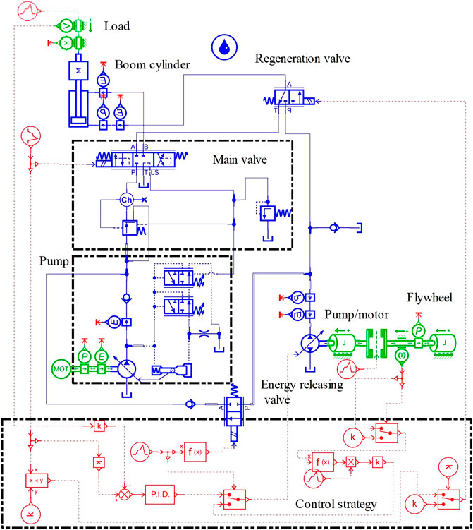
FIGURE 5. Simulation model established in Amesim.
The model was composed of two parts, the original load-sensing system, and the flywheel-based ERS. The original load-sensing system included a boom hydraulic cylinder, a main valve, and a load-sensing pump. Therefore, this model was also used to simulate the original load-sensing system. To regenerate the gravity potential energy, the flywheel-based ERS consisted of a flywheel, a PM, a clutch, a regeneration valve, an energy-releasing valve, and a check valve. As illustrated in Figure 1, the energy regeneration function can be achieved by deactivating the regeneration valve. An electric motor was used to simulate the commonly used internal combustion engine because the engine always works at a constant speed (Chen et al., 2019). In addition, some sensors, such as the power sensor and energy sensor, were used to obtain data for the corresponding components. The pertinent simulation parameters are given in Table 1. Regarding the LS pump and PM, the simulations were carried out assuming constant overall efficiencies. The pump displacement was controlled by the pressure compensator and flow compensator. Like previous studies, the load of the boom cylinder was constant (Wang and Wang, 2012; Chen et al., 2019) and the useful work in the simulation model was null (Xu et al., 2017).
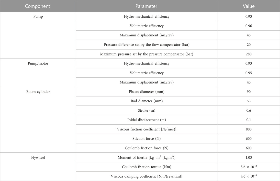
TABLE 1. Pertinent simulation parameter.
Figure 6 shows a complete operation cycle in which the boom is lifted and lowered. The initial displacement of the boom cylinder was 0.1 m and the final displacement was approximately 0.61 m. The maximum extending and retracting speeds of the boom cylinder were the same, at approximately 0.11 m/s.

FIGURE 6. Boom cylinder rod velocity and displacement of the original system.
The pressure curves of the boom cylinder and pump are illustrated in Figure 7.
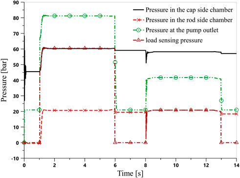
FIGURE 7. Boom cylinder and pump pressure curves of the original system.
In Figure 7, the initial pressure in the rodless chamber of the boom cylinder is approximately 46 bar due to the gravity of the boom. The pressure in the two chambers exhibited a sudden drop and resume at 8 s because the boom cylinder started to retract at this time. The pressure at the pump outlet was always 20 bar higher than the load-sensing pressure. These observations matched well with the characteristics of a load-sensing system. The load-sensing pressure was equal to the pressure in the cap side chamber when the boom was lifting and was equal to the pressure in the rod side chamber when lowering. Because all ports in the center position of the main valve were closed, the pressures in the cap side chamber after the boom cylinder reached the top position and retracted to the bottom position were 59 bar and 57 bar, respectively, which were higher than the initial value of 46 bar.
Figure 8 shows the energy curves of the original system, in which the motor outputs 30.7 kJ of energy to perform a lifting motion and 13.3 kJ of energy to perform a lowering motion. Thus, the pump consumed 44 kJ of energy for one cycle. The difference between the motor output and pump output is due to hydro-mechanical and volumetric losses of the pump, which are described as the pump losses in Section 3. Similarly, the energy difference between the pump output and the boom cylinder input was generated by the pressure drop across the main valve. The energy entering the boom cylinder is greater in the boom-up phase than that in the boom-down phase, and the energy output by the boom cylinder has the opposite trend. The reason is that in the boom-up phase, most of the energy entering the boom cylinder is used to overcome the boom gravity. In addition, in the boom-down phase, the boom potential energy is converted to pressure energy accounting for a main part of the output energy. The energy difference between the input and output in a complete cycle is the friction losses of the boom cylinder, as described in equation (13).
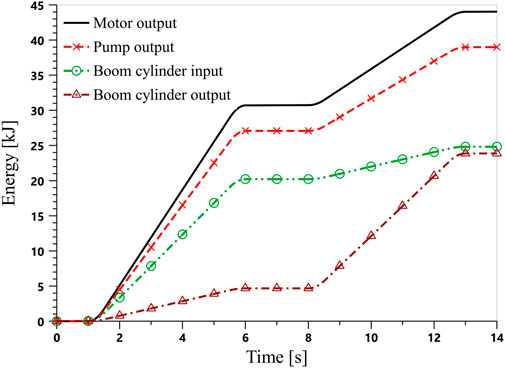
FIGURE 8. Energy consumption of the original system.
With the same joystick signal, simulations of LS-FERS were carried out. However, to validate the energy reutilization effect, another lifting phase was added for LS-FERS. The resting time (13–14 s in Figure 9) of the boom between the lowering phase and the second lifting phase is 1 s, which is shorter than the actual operating time of the excavator. However, this was acceptable because this study only analyzed the recovery and reuse of the potential energy of the boom. The rod velocity and displacement of the boom cylinder are displayed in Figure 9. Compared with Figure 6, the boom cylinder in LS-FERS has the same displacement profile as the boom cylinder in the original system. The velocity in the lifting phases is the same as that in that original system. The velocity in the lowering phase differs from that of the original system because the system in the lowering phase is a displacement control system and it has a lower response than a throttling system. However, these two systems have the same mean velocity in the lowering phase since the retraction stokes are the same.
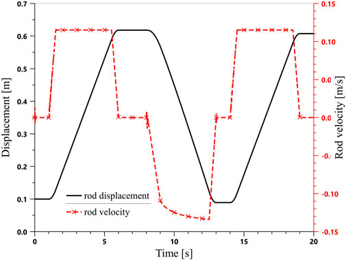
FIGURE 9. Boom cylinder rod velocity and displacement of the proposed system.
The boom cylinder and pump pressure curves of the proposed system are illustrated in Figure 10. These pressure curves highly resemble those in Figure 7. A pressure peak occurs at 8 s because the boom cylinder starts to retract during the low response of the combination of the flywheel and PM. The pressure drop across the main valve is always 20 bar, which is determined by the flow compensator of the load-sensing pump.
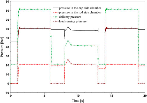
FIGURE 10. Boom cylinder and pump pressure curves of the proposed system.
Figure 11 shows the energy curves of LS-FERS. During the first lifting phase, the output energy of the motor is 30.7 kJ, which is the same as that in the original system. However, 14.1 kJ of energy is needed for the lowering phase, which is a little more than that of the original system. This energy and the potential energy of the boom are converted into mechanical energy by the PM and then transferred to the flywheel. This means that the flywheel energy is increasing as the boom lowers. When the boom reaches its bottom, the energy regeneration is finished and 16.5 kJ of energy is captured by the flywheel. The kinetic energy in the flywheel will gradually decrease due to windage and friction. In the second lifting phase, the flywheel drives the PM operating in pumping mode to provide fluid to the main valve at the cost of consuming the flywheel’s kinetic energy. Therefore, the output energy of the motor is only 15.5 kJ, which is much less than that of the original system. The pump in LS-FERS consumes 29.6 kJ in each cycle. Note that the energy amounts of the PM and flywheel differ by about 6.1 kJ. This is caused by the mechanical and volumetric loss of the PM and the windage and friction loss of the flywheel. The motor energy output curve in Figure 11 shows that the motor power is greater than that before from 17.7 s. This is because the flywheel and PM are not able to deliver enough energy, so the motor should output more to satisfy the system requirement. The pump output curve also shows a similar profile. The energy consumption is summarized in Table 2. Compared with a conventional load-sensing system, the energy-saving efficiency of the proposed system is 32.7% in a complete working cycle.
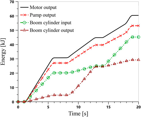
FIGURE 11. Energy consumption of the proposed system.

TABLE 2. Summary of the energy-saving effects.
The power curves of the motor and flywheel are illustrated in Figure 12, in which positive and negative values indicate energy absorption and output by the flywheel, respectively. The motor is the only power source in the first lifting phase and the flywheel is at a standstill. The maximum power is approximately 6.8 kW. When the boom is lowered, the flywheel regenerates the output energy of the boom cylinder, which consists of the boom potential energy and the pressure energy entering the rod side chamber of the boom cylinder. This can explain why the power of the flywheel is greater than that of the motor from 9 s to 12 s. When the boom is lifted for the second time (from 14 s to 19 s), the motor is the only power source within the first 0.25 s. As described in Section 4, when the control signal exceeds its half-maximum valve, the flywheel starts to provide fluid. From 14.5 s to 17.7 s, the flywheel power is greater than the motor power. From 17.7 s, the flywheel cannot satisfy the power demand of the system and the motor will output more power to offset the gap. When the flywheel kinetic energy is exhausted, the motor again becomes the only power source.
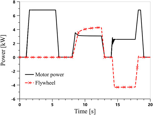
FIGURE 12. Power curves of the motor and flywheel.
Figure 13 demonstrates the energy loss distributions in the boom-down condition of the conventional load-sensing system and LS-FERS. In the conventional load-sensing system, 86% of the total energy loss was caused by the main valve. By adding a flywheel-based ERS, 37% of the energy loss can be regenerated. Unfortunately, the main valve meter-in energy dissipation (33%) is still the largest contributor to the wasted energy. If it is needed to improve system energy efficiency, more attention should be paid to the main valve. The energy losses caused by components related to ERS accounted for 18% of the total energy, which was the second largest contributor. Therefore, employing components with higher efficiency, such as more efficient PM and flywheel, have the potential to reduce energy loss as all the recoverable energy will flow through the whole chain in both directions.

FIGURE 13. Comparison of energy loss distributions.
Our previous research reported a relatively higher energy-saving effect. The two main reasons for the decreased energy-saving effects in the present study are as follows.
• Based on the experiments illustrated in Section 5, compared with reference [], more accurate model parameters were obtained to describe the flywheel-based energy recovery system. However, the new model based on these parameters in the present study has a relatively low energy efficiency compared to that reported previously (Li et al., 2020).
• As shown in Figure 1, any fluid to the boom cylinder should go through the main valve. This will cause energy loss, as discussed in Section 6.2. In comparison, in the previous report (Li et al., 2020), the pressurized fluid provided by the PM was directly delivered to the boom cylinder without any significant throttling loss.
The main contributions of this paper can be summarized as follows:
1) A new load-sensing system with a flywheel-based ERS was proposed and analyzed. The boom potential energy is converted into kinetic energy of the flywheel by using a hydraulic PM when the boom goes down. The regenerated energy is reutilized by pumping fluid to the outlet of the pump to reduce the power demand of the original engine.
2) A simulation model was established in Amesim software, and simulation analysis was carried out to investigate the energy-saving effect. The results showed that the energy-saving efficiency of the proposed system was approximately 32.7% compared with a conventional load-sensing system.
These findings indicate that the flywheel-based scheme is promising for developing energy-efficient HEs. Although the data are not fuel-saving based, they provide a reference for evaluating the energy efficiency of the new system. In the future, it is worth building a full prototype to investigate its energy-saving effect.
The original contributions presented in the study are included in the article/Supplementary Material. Further inquiries can be directed to the corresponding author.
JL and ZJ contributed to the study conception and design. JL and SL performed software simulation and the experiment. JL wrote the draft, and SL and YW revised the manuscript. JL and ZJ provided funding acquisition for this research. All authors contributed to the article and approved the submitted version.
This research was supported by the Jiangsu Overseas Visiting Scholar Program for the University Prominent Young and Middle-aged Teachers and Presidents 2018 (grant number 2018-3), the Jiangsu Qing Lan Project (grant numbers 2022-29 and RSC20201207), the China Postdoctoral Science Foundation (grant number 2022M722671), and the Xuzhou College of Industrial Technology Science and Technology Foundation (grant number XGY2022C006).
The authors would like to express our gratitude to the reviewers and friends who helped us in the process of completing this paper.
Author JL was employed by Xuzhou Villead Heavy Industry Technology Co., Ltd.
The remaining authors declare that the research was conducted in the absence of any commercial or financial relationships that could be construed as a potential conflict of interest.
All claims expressed in this article are solely those of the authors and do not necessarily represent those of their affiliated organizations, or those of the publisher, the editors, and the reviewers. Any product that may be evaluated in this article, or claim that may be made by its manufacturer, is not guaranteed or endorsed by the publisher.
Amirante, R., Cassone, E., Distaso, E., and Tamburrano, P. (2017). Overview on recent developments in energy storage: Mechanical, electrochemical and hydrogen technologies. Energy Convers. manage. 132, 372–387. doi:10.1016/j.enconman.2016.11.046
Bui, N. M. T., Dinh, Q. T., Lee, S. Y., Lee, S. Y., and Ahn, K. K. (August 2015).Study on energy regeneration system for hybrid hydraulic excavator, Proceedings of the Int. Conf. Fluid Power Mechatronics, Harbin, China, 1349–1354. doi:10.1109/FPM.2015.7337331
Casoli, P., Gambarotta, A., Pompini, N., and Riccò, L. (2016). Hybridization methodology based on DP algorithm for hydraulic mobile machinery-Application to a middle size excavator. Autom. Constr. 61, 42–57. doi:10.1016/j.autcon.2015.09.012
Chen, Q., Lin, T., Ren, H., and Fu, S. (2019). Novel potential energy regeneration systems for hybrid hydraulic excavators. Math. Comput. Simulat. 163, 130–145. doi:10.1016/j.matcom.2019.02.017
Dhand, A., and Pullen, K. (2015). Review of battery electric vehicle propulsion systems incorporating flywheel energy storage. Int. J. Auto. Tech-Kor. 16 (3), 487–500. doi:10.1007/s12239−015−0051−0
Ge, L., Quan, L., Li, Y., Zhang, X., and Yang, J. (2018). A novel hydraulic excavator boom driving system with high efficiency and potential energy regeneration capability. Energy Convers. manage. 166, 308–317. doi:10.1016/j.enconman.2018.04.046
Gong, J., Zhang, D., Liu, C., Zhao, Y., Hu, P., and Quan, W. (2019). Optimization of electro-hydraulic energy-savings in mobile machinery. Autom. Constr. 98, 132–145. doi:10.1016/j.autcon.2018.08.011
Hadjipaschalis, I., Poullikkas, A., and Efthimiou, V. (2009). Overview of current and future energy storage technologies for electric power applications. Renew. Sust. Energy. Rev. 13 (6-7), 1513–1522. doi:10.1016/j.rser.2008.09.028
Hedlund, M., Lundin, J., Santiago, J., Abrahamsson, J., and Bernhoff, H. (2015). Flywheel energy storage for automotive applications. Energies 8 (10), 10636–10663. doi:10.3390/en81010636
Ho, T. H., and Ahn, K. K., A study on the position control of hydraulic cylinder driven by hydraulic transformer using disturbance observer, Proceedings of the Int. Conf. Control, Automation Syst. (October 2008). Seoul, Korea: COEX, 2634–2639. doi:10.1109/ICCAS.2008.4694301
Hussaini, H., and Wang, C. (2022). Battery energy storage system control and integration strategy for the more electric aircraft DC grid application. Int. J. Hydromechatronics 5 (3), 275–290. doi:10.1504/IJHM.2022.125093
Joo, C., and Stangl, M. (2016). “Application of power regenerative boom system to excavator,” in Proceedings of the 10th international fluid power conference (Dresden, Germany), 175–184. Available at: https://tud.qucosa.de/api/qucosa%3A29389/attachment/ATT-0/.
Kan, K., Binama, M., Chen, H., Zheng, Y., Zhou, D., Su, W., et al. (2022). Pump as turbine cavitation performance for both conventional and reverse operating modes: A review. Renew. Sustain. Energy Rev. 168, 112786. doi:10.1016/j.rser.2022.112786
Li, J., and Zhao, J. (2021). Energy recovery for hybrid hydraulic excavators: Flywheel-based solutions. Autom. Constr. 125, 103648. doi:10.1016/j.autcon.2021.103648
Li, J., Zhao, J., and Zhang, X. (2020). A novel energy recovery system integrating flywheel and flow regeneration for a hydraulic excavator boom system. Energies 13 (2), 315. doi:10.3390/en13020315
Lin, T., Wang, Q., Hu, B., and Gong, W. (2010). Research on the energy regeneration systems for hybrid hydraulic excavators. Autom. Constr. 19 (8), 1016–1026. doi:10.1016/j.autcon.2010.08.002
Mahato, A. C., and Ghoshal, S. K. (2020). An overview of energy savings approaches on hydraulic drive systems. Int. J. Fluid Power 21 (1), 81–118. doi:10.13052/ijfp1439-9776.2114
Takahashi, K., Kitade, S., and Morita, H. (2002). Development of high speed composite flywheel rotors for energy storage systems. Adv. Compos. Mat. 11 (1), 40–49. doi:10.1163/156855102753613273
Triet, H. H., and Ahn, K. K. (2011). Comparison and assessment of a hydraulic energy-saving system for hydrostatic drives. P. I. Mech. Eng. I-J. Sys. 225 (1), 21–34. doi:10.1243/09596518jsce1055
Wang, H., Zhu, C., Chao, D., Yan, Q., and Fan, H. (2017). Nonaqueous hybrid lithium-ion and sodium-ion capacitors. Adv. Mat. 29 (46), 1702093. doi:10.1002/adma.201702093
Wang, T., and Wang, Q. (2012). Design and analysis of compound potential energy regeneration system for hybrid hydraulic excavator. P. I. Mech. Eng. I-J. Sys. 226 (10), 1323–1334. doi:10.1177/0959651812456642
Wang, T., and Wang, Q. (2014). Efficiency analysis and evaluation of energy-saving pressure-compensated circuit for hybrid hydraulic excavator. Autom. Constr. 47, 62–68. doi:10.1016/j.autcon.2014.07.012
Wasbari, F., Bakar, R. A., Gan, L. M., Tahir, M. M., and Yusof, A. A. (2017). A review of compressed-air hybrid technology in vehicle system. Renew. Sust. Energy Rev. 67, 935–953. doi:10.1016/j.rser.2016.09.039
Xia, L., Quan, L., Cao, D., and Yin, M. (2019). Research on energy saving characteristics of large hydraulic excavator boom driven by dual hydraulic-gas energy storage cylinder. J. Mech. Eng. 55 (20), 240–248. doi:10.3901/JME.2019.20.240
Xu, B., Hu, M., Zhang, J., and Mao, Z. (2017). Distribution characteristics and impact on pump’s efficiency of hydro-mechanical losses of axial piston pump over wide operating ranges. J. Cent. South Univ. 24 (3), 609–624. doi:10.1007/s11771-017-3462-4
Yu, Y., and Ahn, K. K. (2019). Optimization of energy regeneration of hybrid hydraulic excavator boom system. Energy Convers. manage. 183, 26–34. doi:10.1016/j.enconman.2018.12.084
Zhao, D., Chen, M., Dai, Q., and Zhang, E. (2011). System of arm potential energy recovery in hybrid hydraulic excavators. J. Jilin Univ. Eng. Tech.) 41 (s1), 150–154. doi:10.13229/j.cnki.jdxbgxb2011.s1.064
Keywords: energy-saving, energy regeneration, flywheel, hydraulic excavator, load sensing
Citation: Li J, Li S, Ji Z and Wang Y (2023) Design and energy analysis of a flywheel-based boom energy regeneration system for hydraulic excavators. Front. Energy Res. 11:1202914. doi: 10.3389/fenrg.2023.1202914
Received: 09 April 2023; Accepted: 30 May 2023;
Published: 12 June 2023.
Edited by:
Kan Kan, College of Energy and Electrical Engineering, ChinaCopyright © 2023 Li, Li, Ji and Wang. This is an open-access article distributed under the terms of the Creative Commons Attribution License (CC BY). The use, distribution or reproduction in other forums is permitted, provided the original author(s) and the copyright owner(s) are credited and that the original publication in this journal is cited, in accordance with accepted academic practice. No use, distribution or reproduction is permitted which does not comply with these terms.
*Correspondence: Jiansong Li, bGlqaWFuc29uZ0BjdW10LmVkdS5jbg==
Disclaimer: All claims expressed in this article are solely those of the authors and do not necessarily represent those of their affiliated organizations, or those of the publisher, the editors and the reviewers. Any product that may be evaluated in this article or claim that may be made by its manufacturer is not guaranteed or endorsed by the publisher.
Research integrity at Frontiers
Learn more about the work of our research integrity team to safeguard the quality of each article we publish.