 Lei Wang1*
 Xiaochao Hou
- 1State Grid Hebei Electric Power Research Institute, Shijiazhuang, Hebei, China
- 2NARI Technology Nanjing Control Systems Co., Ltd., Nanjing, Jiangsu, China
Classical droop control and virtual impedance methods play crucial roles in improving the system voltage/frequency stability and autonomous power control. Usually, these two methods are often applied as a combination to facilitate load sharing under different line impedance among distributed generators (DGs) in microgrids. They have been developed in two separate concepts, but present strong similarities. In this paper, the comparison of basic droop control and virtual impedance methods is revisited from a new analogy perspective. By combing both of them, a unified multi-degree-of-freedom droop control is proposed with systematic consideration of steady-state power-sharing performance, dynamic performance, and universal applicability of complex line impedance, which is suitable for arbitrary transmission line impedance characteristics. Moreover, this study gives a clear mechanism analysis of virtual inductance to facilitate the P-f & Q-V droop control in complex resistive-inductive microgrid. Finally, the experiment results verify the feasibility of the proposed unified droop control.
1 Introduction
Microgrids have emerged as an effective means of integrating distributed renewable power generation units such as wind and photovoltaic power into the grid and serving as an important supplement to future power systems (Hu et al., 2023; Yin et al., 2023). They offer several benefits including reduced investment in existing power equipment, decreased transmission losses, and improved power supply quality. Microgrids can be utilized in a variety of scenarios including independent power supply systems with special requirements such as aerospace systems and data centers, distributed renewable energy integration systems with high penetration levels, and remote areas with weak connections to the main grid. As a complex islanded power supply system comprising high penetration distributed sources and loads, microgrids present significant challenges in terms of power sharing control and system frequency/voltage stability in the off-grid mode that warrant extensive research (Lasseter and Paigi, 2004; Hou et al., 2020; Liu et al., 2022).
The operation control methods of the microgrids can be classified into three main categories: 1) Centralized control strategies based on a master-slave control structure, including communication-based centralized control (Guo et al., 2022) and master-slave control (Pei et al., 2004); 2) Hierarchical control based on integrated intelligent management (Guerrero et al., 2010; Guerrero et al., 2012); and 3) Peer-to-peer control strategies based on a plug-and-play architecture, including distributed control with communication (Bidram et al., 2014; Dou et al., 2016) and decentralized control without communication (Hou et al., 2022). However, centralized and hierarchical control strategies rely on high-bandwidth communication networks, resulting in high communication costs and reduced reliability. As such, these strategies may not be suitable for highly-reliable microgrid systems with high penetration levels of renewable energy sources.
Decentralized control strategies based on droop control principles have been shown to enable peer-to-peer control without communication in microgrids and have garnered significant research interest. Despite its advantages, droop control has several inherent limitations (Han et al., 2016): 1) It is heavily dependent on the line impedance characteristics and requires transmission lines to exhibit inductive behavior; 2) System frequency and voltage are influenced by load power demand, resulting in deviations in voltage frequency and amplitude; and 3) Mismatches in line impedance can lead to inconsistent output voltage amplitudes among micro sources, preventing the achievement of reactive power equalization.
To address the sensitivity of basic droop control to line impedance characteristics, the virtual impedance method is widely utilized to decouple active-reactive power P-Q and compensate reactive-power differences among the various DGs due to the line impedance mismatches. Several studies (Guerrero et al., 2004; Mohamed and El-Saadany, 2008) have proposed a control strategy that combines virtual impedance and droop control. This approach can reshape line impedance characteristics and thereby ensuring the feasibility and applicability of droop control under varying line impedances. However, these studies do not provide a detailed parameter design guideline of virtual impedance for system stability. In remote low-voltage power distribution areas with high line resistance, large virtual inductance is required to meet system line inductance requirements. This can result in excessive voltage drop and reduced transmission capacity. To improve system stability under complex line impedance conditions, droop control within the virtual coordinate transformation framework has been proposed in (De Brabandere et al., 2007; Li and Li, 2011). However, due to the use of virtual power for droop feedback, accurate power-sharing cannot be achieved. Then, some other power-sharing control methods have been proposed for AC microgrids with low-voltage highly-resistive line characteristics, including active power-amplitude (P-V) droop and reactive power-frequency (Q-ω) droop control strategies (Tuladhar et al., 2000; Yu et al., 2010), power angle droop (Majumder et al., 2009; Majumder et al., 2010), intelligent algorithm-based droop control (Bevrani and Shokoohi, 2013), and decoupling-based droop control (Wu et al., 2015; Guan et al., 2016; Shi et al., 2022). However, there is no unified droop control strategy that can ensure stable system operation under arbitrary line characteristics, achieve accurate active power sharing among micro-sources, and realize satisfactory dynamic performance.
To fill this gap, this paper revisits the basic droop control and virtual impedance methods from a new analogy perspective and proposes a unified droop control that is suitable for arbitrary transmission line impedances. The main contributions can be drawn as follows.
1) The P-Q coupling relationship of active and reactive power under different line impedance characteristics is given, and the inherent control mechanism of the virtual impedance method is revealed as a special proportional-differential (PD)-based droop control from a new analogy perspective.
2) A unified droop control with multi-degree-of-freedom is proposed to ensure universal applicability under arbitrary highly-inductive, complex impedance, and highly-resistive line characteristics. The mechanism analysis of virtual inductance to facilitate the P-f & Q-V droop control in complex resistive-inductive microgrid is clearly presented.
3) By stability sensitivity and mechanism analysis, the feasibility of the proposed unified droop control mechanism is given under different line impedances. Key control parameters design guideline is also provided for the application of the proposed unified droop control in engineering practice.
The rest of this paper is organized as follows. In Section 2, the power transmission models under different line impedances are described. The analogy of classical droop control and virtual Impedance is presented with a proposed untied droop control in Section 3. System stability and control mechanism under different line impedances are analyzed to adjust the parameters in Section 4. In Section 5, three experimental cases are virified. Lastly, the conclusion and future work follow in Section 6.
2 Power transmission models under different line impedances
2.1 Equivalent model of single-unit infinite-bus
For parallel multi-inverters of AC microgrid, each distributed generation unit can be regarded as an equivalent voltage source node of the system, including voltage-magnitude control and phase-angle-vector control. And the public coupling connection point of a multi-parallel converter can be approximated as an infinity bus when the number of parallel modules is relatively large, thus simplifying the system analysis and design. As shown in Figure 1, the equivalent physical circuit diagram of a distributed power electronic converter unit connected to a common infinity grid-connected bus is given. From Figure 1, it can be seen that the output current and apparent power of the distributed power generation unit can be expressed as
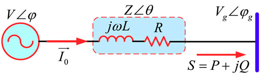
FIGURE 1. Equivalent physical circuit diagram of the grid-connected unit.
In Figure 1,
Combining with Eqs 1, 2, the output active power and reactive power of the distributed grid-connected power conversion unit are expressed as
In Eqs 3, 4, δ is the voltage phase angle difference (power angle concept) between the grid-connected power conversion unit and the common coupling bus, which can be expressed as
To further clearly visualize the coupling relationship of the active/reactive power output from the grid-connected power conversion unit and their variation with voltage amplitude and power angle, the power circle curve for power impact analysis is depicted in Figure 2 from Eqs 3, 4, where the center of the circle is
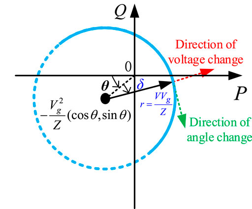
FIGURE 2. Schematic diagram of the power circle of the grid-connected power electronic conversion unit.
2.2 Simplified power model under different line impedance characteristics
It is well known that the output line impedance characteristics of power electronic systems are significantly different at different voltage levels. As shown in Table 1, in the high-voltage transmission line, the line impedance characteristics are approximated as highly inductive (θ = 72.8°); in the medium-voltage transmission line, the line impedance characteristics are approximated as complex resistive-inductive impedance (θ = 50°); in the low-voltage transmission line, the line impedance characteristics are approximated as highly resistive (θ = 7.5°). To simplify the subsequent theoretical analysis, the line impedance characteristics at the three voltage levels are replaced by purely inductive, equally resistive-inductive, and purely resistive types, respectively.

TABLE 1. Comparison of line impedance characteristics at different voltage levels.
Further, from Eqs 3, 4, the simplified models of active and reactive power under different line impedance characteristics are given in Table 2. And a schematic diagram of the power circle under different line impedance characteristics is drawn, as shown in Figure 3. It is derived that under the assumed purely inductive line (θ = π/2), the active power output regulation basically relies on the power angle, while the reactive power output regulation mainly relies on the voltage magnitude difference. Under the purely resistive line (θ = 0), the coupling of active and reactive power is just the opposite, and the transmission of active and reactive power relies on the voltage magnitude difference and voltage power angle, respectively. In addition, when the resistance is comparable (θ = π/4), the transmission of active and reactive power is affected by the voltage power angle and voltage magnitude difference, which makes the coupling mechanism more complicated and increases the difficulty of the controller design. In addition, considering the line transmission capacity under different line impedance characteristics and the feasible power angle domain constraint (δ∈ [-π/2, π/2]), the solid line power circle curves of Figure 3 represent the feasibility interval.
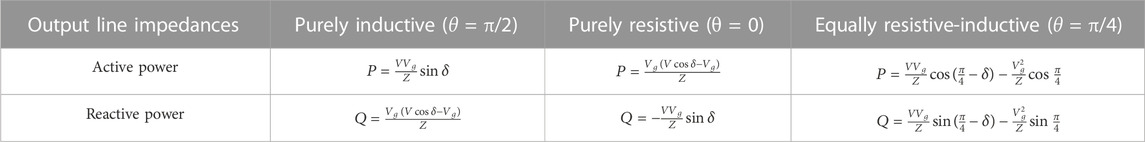
TABLE 2. Simplified power model under different line impedance characteristics.
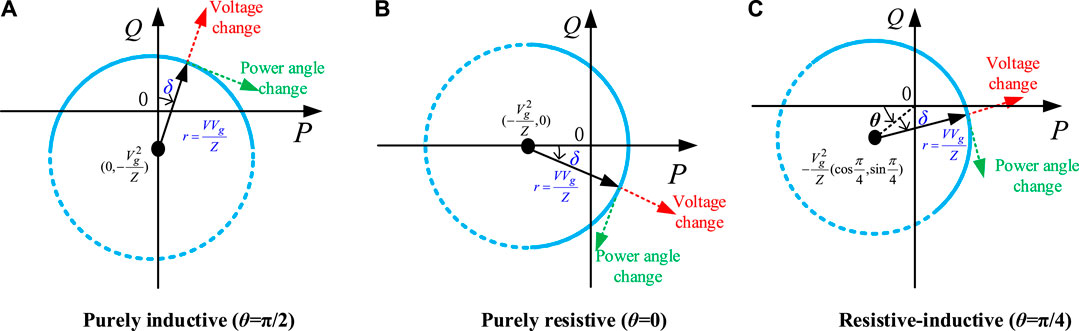
FIGURE 3. Diagram of power circle unit under different line impedance characteristics. (A) Purely inductive line; (B) purely resistive line; (C) Equally resistive-inductive line.
3 Analogy of classical droop control and virtual impedance: A untied droop control
3.1 Basic principle of classical P-ω/Q-V droop control
For AC microgrids, basic P-ω/Q-V droop control has become one of the most mainstream decentralized control strategies due to its high reliability, plug-and-play characteristics, and non-communication self-synchronization. The basic principle is to feedback on the locally-collected active and reactive power signals to control the regulated output voltage frequency and amplitude reference, respectively. In addition, the natural essence of conventional droop control is to simulate the natural synchronous generator external output characteristics, so conventional active-frequency droop control has the global frequency autonomous synchronization capability, which can guarantee the exact proportional active power sharing among multiple parallel inverters without any communication condition. Its steady-state expressions are presented as follows.
In Eqs 6, 7, ωr and Vr are the voltage angular-frequency reference and voltage magnitude reference of the individual inverter; ω* and V* are the angular frequency given and voltage magnitude given under rated-condition; m and n represent the active-frequency droop and reactive-voltage droop gain, respectively; P* and Q* are the rated active power and reactive power of individual inverter; ωmax and ωmin represent the maximum and minimum values of angular frequency allowed for normal operation of the system; Vmax and Vmin represent the maximum and minimum values of voltage allowed for normal operation of the system. ωmin and ωmax represent the maximum and minimum values of angular-frequency allowed for normal system operation; The specific droop control curves are shown in Figure 4.

FIGURE 4. Schematic curves of droop control. (A) Active-frequency and (B) reactive-voltage.
The overall control scheme of a single voltage-source inverter containing droop control is shown in Figure 5. Its physical inverter circuit is mainly composed of a source terminal, power electronic switch, LC filter, and parallel line impedance, and its controller is mainly divided into local signal acquisition, power calculation, droop control loop, double voltage-current tracking closed-loop and SPWM modulation. In particular, the droop control link provides the voltage frequency and amplitude reference for the voltage loop tracking control based on the locally calculated output active power and reactive power signals. In general, the calculation of the average active and reactive power requires first-order low-pass filtering of the instantaneous power, and the control bandwidth is designed to be approximately (2–10) Hz. In addition, for fast and accurate tracking of the outer-loop voltage reference, the voltage loop control is designed to have a medium bandwidth of approximately (400–600) Hz. Such a bandwidth design ensures that the four control links of power, voltage, current, and modulation loops are effectively separated in time scale, which facilitates the overall design and dynamic response of the inverter controller.
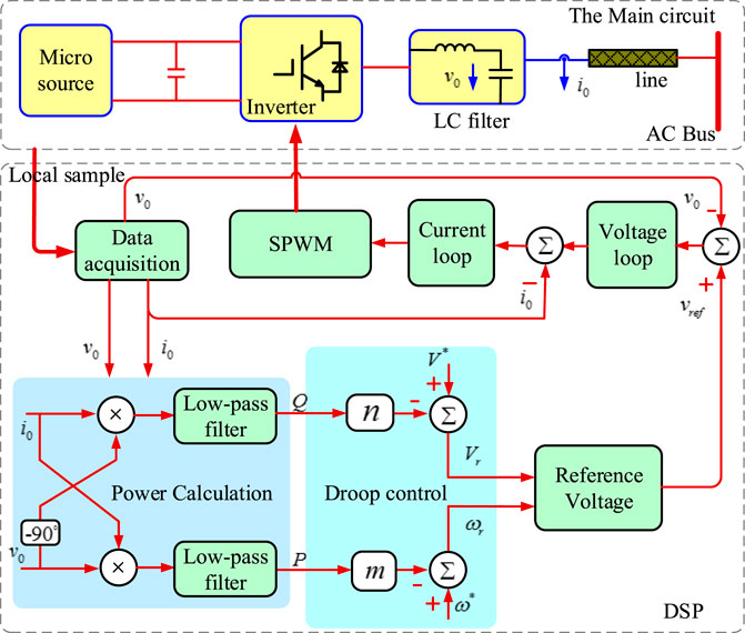
FIGURE 5. Overall control scheme for a single inverter with basic droop control.
It is worthwhile to note that although conventional droop control forms the basis for decentralized control of parallel inverter systems, it still has some shortcomings of its own: 1) Dependence on highly-inductive output impedance, presence of active-reactive power coupling; 2) Poor dynamic adjustment; 3) Line mismatch leading to uneven reactive power sharing.
3.2 Revisiting control mechanism of virtual impedance
For the intuitive physical concept of virtual impedance, it is introduced to reshape the overall output impedance characteristics of inverters. To solve the problem of line impedance mismatch between multiple parallel inverters, the total output impedance is flexibly adjusted to highly-inductive, highly-resistive, or complex impedance according to the control target requirements. The virtual impedance is analyzed on the active power-reactive power from the theoretical and practical application perspectives. The influence of virtual impedance on the power dynamic decoupling ability, power oscillation damping ability, tidal current control ability, and system fault current limiting ability is further analyzed.
Figure 6 gives the overall control block diagram of a single inverter containing virtual impedance. From it, the mathematical expression of the virtual impedance is given as
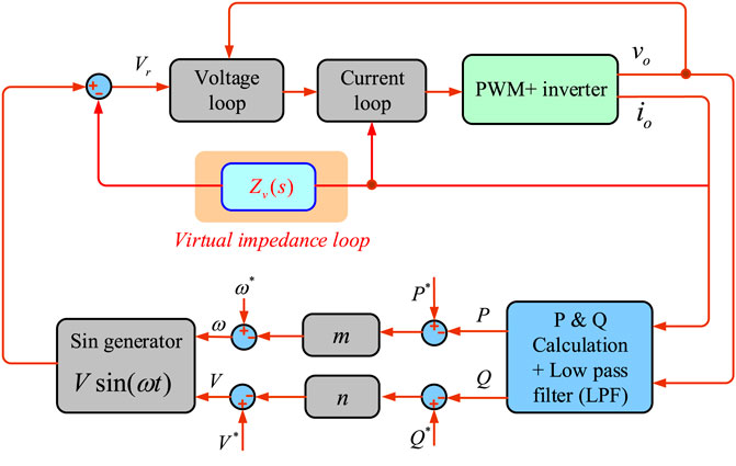
FIGURE 6. Overall control block of a single inverter including virtual impedance.
In Eq. 8,
As seen in Figure 6, the intuitive concept of virtual impedance is to multiply the impedance to be virtualized with the output current vector. And it is subtracted from the voltage loop reference in the expectation of changing the impedance characteristics of the original line. It is worth mentioning that the virtual impedance is mainly used for steady-state sharing and dynamic response performance regulation, without current dynamic filtering and real active losses, compared to the actual physical impedance configured directly in series at the grid-connected inverter.
From the traditional perspective based on intuitive physical concepts, the goal of introducing the virtual impedance concept in a multi-parallel inverter is to reshape the overall equivalent output impedance of the inverter, as shown in detail in Figure 7, where the equivalent output impedance contains both the constructed virtual impedance and the actual physical line impedance. However, from the perspective of exploring the real control connotation of virtual impedance, its essential control law is to multiply the virtual impedance with the output current vector and feed it back to the internal reference of the output voltage at the front end of the voltage loop. In other words, the control law of virtual impedance can be studied and analyzed from a new control perspective to investigate the effect of virtual impedance on the actual output node characteristics of the voltage source and try to replace the current feedback with power feedback. In this way, a new outer power-loop control law is constructed to equate the effect of the inner-loop output impedance, providing new ideas for distributed units that want to reshape the output impedance.
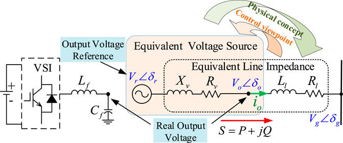
FIGURE 7. Two perspective comparisons of virtual impedance: intuitive physical concept and real control mechanism.
From Figure 7, the mathematical relationship between the output power of the inverter and the virtual impedance can be obtained as
Replacing the output power in Eq. 9 with the output current in Eq. 8, the derivation yields the voltage difference and phase angle difference triggered by the output active and reactive power on the virtual impedance, respectively, expressed as
In Eqs 10, 11, since the output voltage amplitude is around the rated voltage (within approximately 5% deviation), the steady-state values of Vr and Vo can be replaced by V* for ease of analysis and expression. Thus, the core control law of the virtual impedance is further expressed as
Rewrite Eq. 12 under the frequency coordinate framework
where,
From Eqs 12, 13, it is derived that the virtual impedance control law is a combination of Eq. 13 power angle droop and Eq. 12 voltage droop control, especially finding the influence law of virtual inductor Xv and virtual resistance Rv on the phase angle and voltage amplitude regulation, respectively. Therefore, the mx, mr, nx, nr parameters can be designed flexibly to replace the role of virtual impedance, and have higher parameter freedom than virtual impedance.
In addition, the establishment of this equivalent relationship, in Eq. 13 power angle droop control, increasing the δ -P droop coefficient mx is essentially an equivalent increase in virtual inductance, which in turn compensates for the overall output impedance at the active control level. Thus, it can improve active power sharing accuracy. Meanwhile, in the voltage droop control of Eq. 12, increasing the V-Q droop coefficient nx is essentially an equivalent increase in virtual inductance, which in turn compensates the overall output impedance at the reactive power control level and can improve the reactive power sharing accuracy, and also illustrates the root cause of the inability to achieve accurate sharing of voltage-reactive power droop. Moreover, in the system stability analysis, it can also be explained from the perspective of virtual inductance that a moderate increase in the virtual inductance equivalent parameter mx can appropriately improve the system dynamic response and damping power oscillation capability, but an excessive droop factor mx is equivalent to increasing the impedance of the system, which will affect the power transmission capability of the inverter and lead to an excessive steady-state power angle of the system, which is not conducive to system stability.
In a multi-parallel inverter AC microgrid, the virtual inductor-dominated approach is often used to satisfy the condition that the conventional droop is dominantly inductive by Eqs 12, 13, and the control law of the virtual inductor (Rv = 0) is given here separately as follows.
3.3 Analogy between droop control and virtual impedance: A special PD droop method
In order to transfer the control law of the virtual inductor from under the phase angle coordinate to under the frequency coordinate, Eq. 15 can be calculated by taking the differential, and the virtual inductor is then equated to a new frequency droop.
In Eq. 17, ωr is the nominal reference value of the angular frequency. It follows that the virtual inductor can be understood as an active differential type of frequency droop.
Further, when the multi-parallel inverter contains both conventional frequency droop and virtual inductance control, a combined droop control method is presented by combining Eqs 6, 17, 7, 16.
Eq. 18 is a frequency droop control with proportional-differential (PD) feedback power control. In addition, from Eq. 19, the reactive-voltage droop gain nx from the virtual inductor equivalent is superimposed on the droop coefficient of the Q-V control, confirming the homology and equivalence of using virtual inductor control and increasing the reactive droop gain analyzed above. Among them, mx mainly regulates the dynamic performance of the system, and nx dominates the stability of the system. By setting the mx and nx parameters reasonably instead of the virtual inductance, the combined droop control is universally applicable under any highly-inductive, inductance-resistance, and resistance-inductance line characteristics. At the same time, it also provides a new idea for mapping the droop feedback control law to the physical concept of virtual impedance.
3.4 Proposed united multi-degree-of-freedom droop control
The combined droop control in Eqs 18, 19 extends the general applicability of conventional droop control under complex line impedance and ensures autonomous frequency synchronization and accurate active power sharing among multiple inverters. Inspired by this, in order to simultaneously take into account the basic control objectives of steady-state sharing performance and dynamic response, as well as the universal applicability under complex line impedance, this paper further proposes a united multi-degree-of-freedom decentralized synchronous control method.
where Hij (s) is the proportional-integral-derivative (PID) operator, expressed as
Compared with the combined droop control in Eqs 18, 19, the unified multi-degree-of-freedom control framework in Eq. 20 has two significant improvements: 1) one is to use the proportional-integral-differential (PID) operator instead of the traditional proportional operator; the proportional operator can flexibly adjust the steady-state operating effect; the integral operator can be applied to the dual-mode switching operation of parallel and off-grid, and the differential operator can flexibly adjust the system dynamic damping; 2) The second is the use of feedback active-reactive coupling-matrix, which can realize the dynamic decoupling of active and reactive power through flexible design parameters and greatly improve the system stability.
The multi-degree-of-freedom means that the proposed united droop control has multi-functions with systematic consideration of steady-state power-sharing performance, dynamic performance, and universal applicability of complex line impedance. For the unified multi-degree-of-freedom droop control framework, the parameters can be flexibly selected according to different control objectives to facilitate comprehensive and optimal design, which is illustrated by the following examples.
1) With regard to the proportional operator, the priority is given to the steady-state active power sharing while ensuring the synchronization of the autonomous frequency of the system, which is generally chosen from
2) Regarding the integration operator, in order to adapt to dual-mode operation with and without the grid, Hij s) generally contains the integration operation (
3) With respect to the differential operator, the active or reactive power oscillations can be effectively damped by the flexible selection of appropriately sized differential operators
4) Conventional droop control applied under highly-inductive line impedance can be seen as a special case of a united control framework with a non-zero main diagonal and a zero anti-diagonal feedback coupling matrix.
5) When the main diagonal is all zero and the opposite diagonal is not zero, it can be applied to resistive lines for reactive-frequency control and active-voltage control.
6) The influence law of 3*4 = 12 parameters in the feedback coupling matrix can be studied by the participation factor and sensitivity analysis methods, which can provide guidance for the application of decentralized control of parallel-type inverter networks in engineering practice.
4 Stability and mechanism analysis under different line impedances
4.1 Stability analysis
In order to investigate the influence of control parameters on system stability and dynamic response in the unified multi-degree-of-freedom droop control framework of Eq. 20, this section focuses on the small-signal stability analysis of the power outer-loop control dynamics of the grid-connected inverter system. The steady-state operating point of the system is denoted by capital letters as (V, Vg, δ), and the small-signal disturbance terms are denoted as
First, the power transfer characteristics of Eqs 3, 4 are linearized as follows.
In Eq. 22, G is the gain matrix
Second, considering that the active and reactive power averages in Figure 5 are obtained after first-order low-pass filtering, the linearized model of the unified multi-degree-of-freedom droop control of Eq. 20 can be obtained as
Transforming the frequency coordinate system in Eq. 25 to the power-angle coordinate system, it is further reduced to
In Eq. 26, H(s) is the feedback matrix that
Coupling (22), (23) and (26), (27), the system closed-loop transfer function can be obtained as
In summary, the influence of control parameters or physical parameters on the stability and dynamic response of the system can be derived by analyzing the trend of the dominant pole of the closed-loop transfer function of Eq. 28 with the variation of parameters.
To verify the general applicability of united droop control under different line impedance characteristics, root trajectory tests are conducted for systems with highly-inductive, equally resistive-inductive, and highly-resistive line characteristics, respectively. Thus the effects of active and reactive droop coefficients and power filtering constants on system stability are investigated. The specific system parameters are shown in Table 3. The specific root trajectory result is shown in Figure 8.
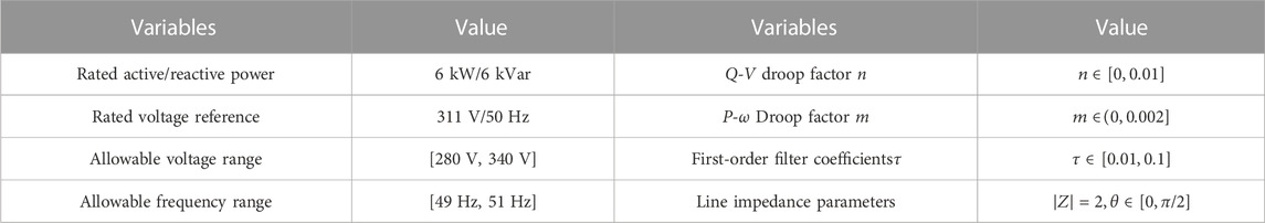
TABLE 3. Physical and control parameters of the inverter.
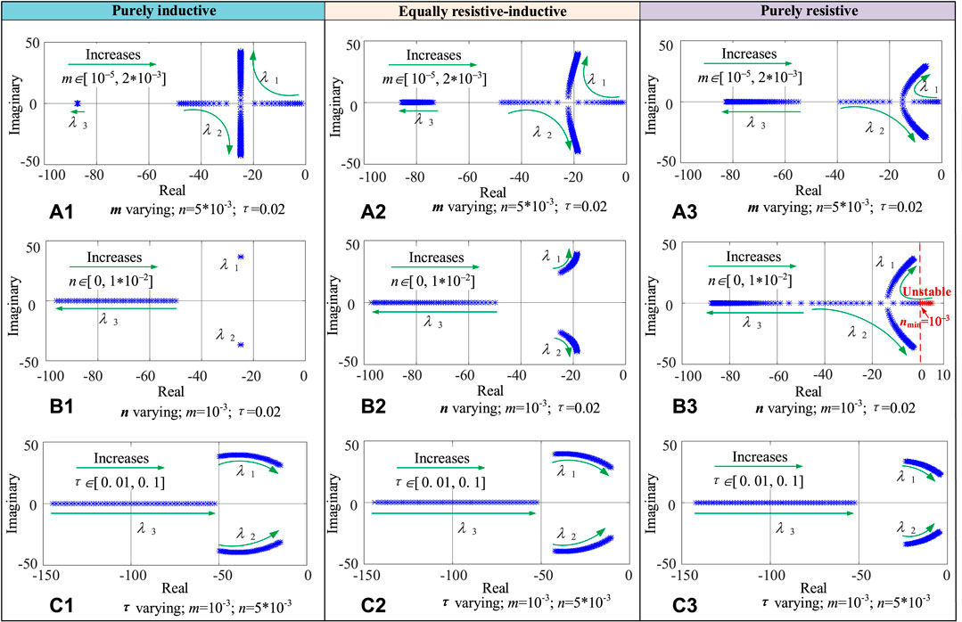
FIGURE 8. Root trajectory analysis under three line impedances (A) m variation; (B) n variation; (C) filtering constant τ variation.
The following brief conclusions can be drawn from Figure 8.
1) Under the three-types line impedance characteristics, the active droop coefficient m has a relatively large impact on the dynamic response of the system, when m is too small, the system is over-damped state; when m is increased moderately, a pair of conjugate dominant poles λ1 and λ2 will appear, in order to ensure a better dynamic response of the system, the conjugate poles are generally selected as the imaginary part of the value than the real part of the value is located in the range of 0.707–1.414; if m is increased all the time, it will appear under-damped If m is increased all the time, the system will be underdamped, which is not good for the dynamic response.
2) In the highly-inductive and equally resistive-inductive line impedance characteristics, the reactive droop coefficient n has almost no effect on the system stability and dynamic response. However, in the highly-resistive line impedance characteristics, the system stability requires that n cannot be too small, only when it is greater than 0.001 begins to gradually stabilize, according to the above Eq. 14 in the virtual inductance and droop coefficient of quantitative control relationship, can be equated to the virtual inductance
3) Under the three-type line impedance characteristics, the power filtering constant τ varies within a certain range [0.01, 0.1] with negligible effect on the system stability, but too large a filtering constant, which is equivalent to a delay in the power calculation time, is not conducive to system stability.
The above analysis confirms the feasibility of united droop control under different impedance characteristics, especially for the system under highly-resistive characteristics, which can be designed from two perspectives of mutual mapping of virtual inductance and droop coefficient, and the reactive droop coefficient n is reasonably selected to ensure system stability.
4.2 Mechanism analysis and turning guidelines of control parameters
The above analysis shows that the active power droop coefficient m and the filtering time constant τ mainly affect the transient response of the system, and their effects on stability can be approximately ignored within the normal parameter range. In addition, the reactive droop coefficient n has basically no effect on the stability in the case of purely-inductive and purely-resistive lines, but in the case of purely resistive, the reactive droop coefficient n is critical and directly related to the stable operation of the system. In order to further verify the reasonableness of the above root trajectory analysis, this section will analyze the reason from the perspective of the small signal control block diagram.
According to the small-signal analysis, the overall small-signal block diagram models of the stand-alone system in the purely-inductive, equally resistive-inductive, and purely-resistive lines are shown in (a.1), (a.2), and (a.3) in Figure 9, respectively. As seen, the strength of the internal coupling effect of the active-reactive control loop varies for different line impedance characteristics: in the purely-inductive case, there is basically no coupling; in the complex resistive-sensitive line and the purely resistive case, the coupling effect is stronger. In order to clearly express the decomposed active and reactive control in the three cases, the small-signal simplified block diagrams are shown in (b.1)-(b.3) and (c.1)-(c.3), respectively.
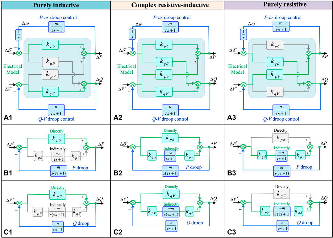
FIGURE 9. Control block diagram under different line impedances. (A) Overall small-signal block diagram; (B) decomposed active control; (C) decomposed reactive control.
In the small-signal block diagram of active-power frequency control, there are two pathways of direct and indirect coupling effects of the power angle on the forward pathway gain of the output active power, mathematically expressed as
where
In the block diagram of reactive-power voltage magnitude control, there are two pathways of direct and indirect coupling effects of voltage on the gain of the forward pathway of output reactive power, mathematically expressed as
where
As seen in Eqs 30, 32, the forward path gain is positive due to power indirect coupling regardless of the characteristics of the line parameters, enhancing the ability of the system power angle to regulate active power (δ-P) and voltage to regulate reactive power (V-Q). Thus, indirect coupling, although it may lead to coupling of the transient response between active and reactive power of the system, inherently facilitates the stability of the system, which in turn ensures the applicability of conventional droop at various line impedances.
To briefly analyze the weights of direct and indirect coupling at different line impedances. Under the conditions of neglecting the system dynamic characteristics (neglecting the power filtering characteristics) and the small power angle of the system operation, the power coupling characteristics of the micro-source under different line impedance conditions are given in Table 4. Among them, since the range of power angle of the microgrid generally operates in the interval [-π/6, π/6], it can be considered as follows:
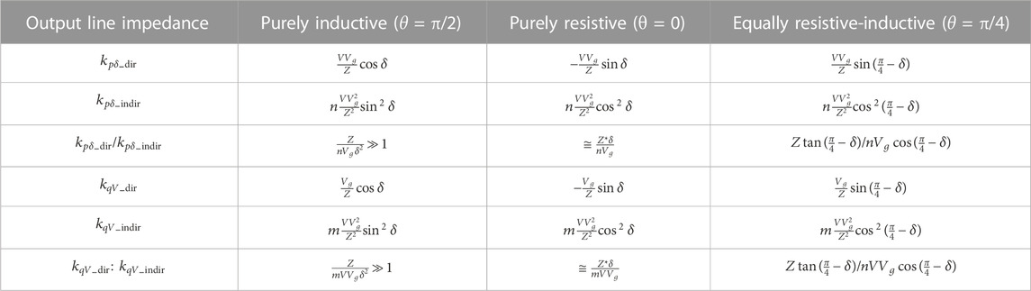
TABLE 4. Power coupling characteristics based on different line impedance conditions.
Under the highly-inductive line, the direct coupling of both active and reactive power control is much greater than the effect of indirect coupling, so the system has a good decoupling capability.
In the case of equally resistive-inductive lines, the direct and indirect coupling of micro-sources are positive and in the same order of magnitude, both of which are conducive to the ability of power angle regulation of active power and voltage regulation of reactive power to ensure that the system is always stable.
Under the purely-resistive low-voltage microgrid, the active and reactive power control in the steady-state power angle is positive, and the influence factor of its direct coupling is negative, which is not conducive to the stability of the system. However, with the moderate increase of the adjustable parameter n, the indirect coupling will gradually dominate, and the system will tend to be stable. The critical point of the system stability is the sum of the two forward channels is a positive number, i.e.,
Combining Eq. 30; Table 4, the key conditions for system stability in the case where the line is purely-resistive are
In the microgrid, since the voltage of the common bus is approximately equal to the rated voltage V* within the allowed deviation from the rated voltage, Vg in Eq. 30 can be approximated by V* instead. In addition, the power angle range of the microgrid generally operates in the interval [-π/6, π/6], which can be considered as:
Considering the voltage quality of the microgrid, the design principle of the reactive power droop factor of low-voltage resistive microgrid is
5 Experiments of proposed united droop control under different line impedances
In order to verify the effectiveness and feasibility of the proposed united droop control under different line impedance characteristics, an experimental platform of a three-inverter parallel system was built with the physical main circuit and parameters as shown in Figure 10, which mainly contains the DC power supply, inverter, filter, line impedance, and load. The control scheme of three inverters is presented in Figure 11. The rated AC reference voltage and frequency of the system is 312V/50 Hz. The DC-side voltage and virtual impedance of three inverters are 400V and 0.2, respectively.
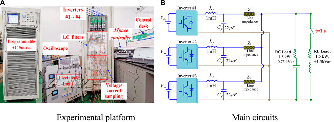
FIGURE 10. Prototype setup of the experiment. (A) Experimental platform; (B) main circuits.
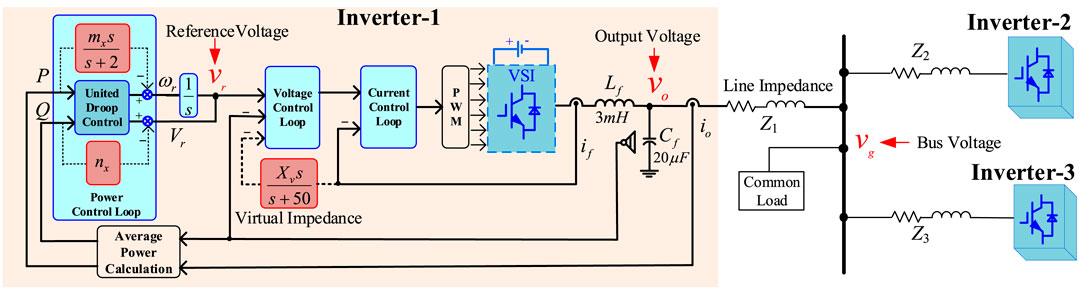
FIGURE 11. United Control Scheme of the three-inverter parallel system.
According to the different line impedance characteristics in Table 1, this section verifies the operation of the united droop control under three line characteristics: highly-inductive (impedance angle θ = 0.404π), complex impedance (impedance angle θ = 0.278π) and highly-resistive (impedance angle θ = 0.042π), respectively, and the specific line impedance parameters and control parameters of the three groups are shown in Table 5. According to Figure 10, only the RC load (1.5 kW, −0.75kVar) was connected to the system in the initial stage of the experiment; to test the dynamic response of the control method under load switching, a new RL load (1.5 kW, +1.5 kVar) was cut in after t = 1s.
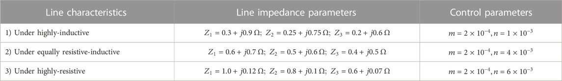
TABLE 5. Physical line parameters and control parameters of the experiment.
5.1 Under highly inductive line impedance
The experimental results under highly inductive line impedance are given in Figure 12. The four experimental waveforms in Figure 12A are the output currents i1 ∼i3 and common bus voltages ubus of the three inverters. It is seen that the system has high-quality output voltage and current. From Figure 12B and Figure 12D, it is concluded that the three inverters can achieve accurate active power sharing and frequency autonomous synchronization before and after load switching. From Figure 12C, E it is concluded that the global voltage inconsistency is caused by the mismatch of the output line impedance values of the three inverters, so the accurate reactive power sharing cannot be guaranteed, and the reactive power sharing can be ensured by adjusting the reactive droop gain within the acceptable deviation range. For the dynamic response in switching load, the system regains a new steady state after about 5 fundamental frequency cycles with good dynamic response capability.
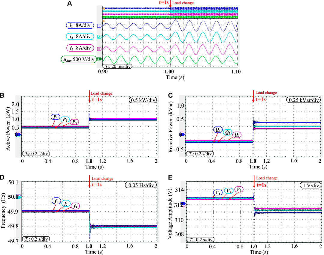
FIGURE 12. Experimental results under highly inductive line characteristics. (A) output waveforms; (B) active power; (C) reactive power; (D) frequency; (E) voltage ampltitude.
5.2 Under complex resistive-inductive line impedance
Figure 13 gives the experimental results under the resistive-inductive equivalent line characteristics. Figure 13A shows the output currents i1 ∼i3 and the common bus voltage ubus of the three inverters. From Figure 13B, it is concluded that the active power of the three inverters has been in the sharing state before and after load switching, and has a good dynamic response. And the reactive power can only be roughly equalized, and the comparison with the results under highly-inductive line impedance reveals that the results are basically similar except for the different precision of steady-state reactive power sharing. And the increased part of line resistive components basically does not change the dynamic and steady-state performance of the system.
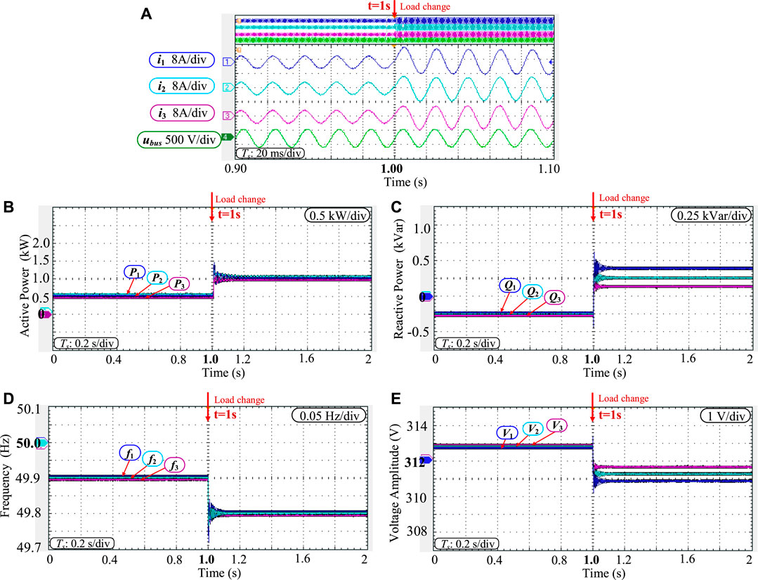
FIGURE 13. Experimental results under the equally resistive-inductive line characteristics. (A) output waveforms; (B) active power; (C) reactive power; (D) frequency; (E) voltage ampltitude.
5.3 Under highly resistive line impedance
The experimental results of united droop control under highly-resistive line characteristics are given in Figure 14. Figure 14A shows the output currents i1 ∼i3 and common bus voltages ubus for the three inverters. Compared with the cases under highly-inductive and equally resistive-inductive line impedance, the Q-V droop gain n must be a larger value to strengthen the indirect coupling of Figure 9. The value n is given in Table 5 according to the design guideline Eq. 36. From Figure 14B, it is concluded that the active power of the three inverters before and after load switching has been in the state of equal division with a good dynamic response, and from Figure 14C it is concluded that the reactive power has not reached the exact equal division due to the line impedance mismatch. Comparing with the results under highly-inductive and equally resistive-inductive line impedance, it is found that the active power and frequency synchronization results are basically similar except for the different precision of steady-state reactive power sharing, which achieves the universal applicability of united droop control under highly-inductive, equally resistive-inductive, and highly-resistive line impedances ensures the frequency synchronization while giving priority to the accurate active power sharing, and ensures the uniformity of the control method in different applications.
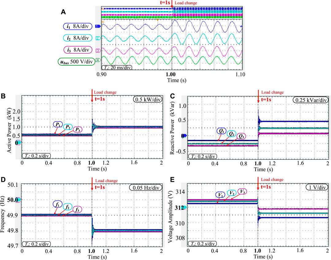
FIGURE 14. Experimental results under highly-resistive line characteristics. (A) output waveforms; (B) active power; (C) reactive power; (D) frequency; (E) voltage ampltitude.
6 Conclusion
This paper revisits the basic droop control and virtual impedance methods from a new analogy perspective and proposes a unified droop control that is suitable for arbitrary transmission line impedances. The coupling relationship between active power and reactive power under different line impedance characteristics is revealed. And a unified droop control is proposed that takes into account steady-state power-sharing performance, dynamic performance, and universal applicability of complex line impedance, ensuring universal applicability under arbitrary line characteristics. Because the proposed method can achieve autonomous frequency synchronization and accurate active power sharing simultaneously in a decentralized manner, it has the advantages of communication-cost saving and increased system reliability. Finally, the experiment results verify the feasibility of the proposed unified droop control under the characteristics of highly-inductive, equally resistive-inductive, and highly-resistive line impedances. For future work this revisiting study can inspire researchers to enhance the decentralized droop methods for multiple parallel inverters.
Data availability statement
The data analyzed in this study is subject to the following licenses/restrictions: Academic study. Requests to access these datasets should be directed to aG91eGlhb2NoYW9AdHNpbmdodWEuZWR1LmNu.
Author contributions
Conceptualization, LW, XH, and XH; methodology, TL and ZC; software, ZL, ZL, and JH; validation, LW and TL; resources, LW and ZL; writing—original draft preparation, LW, ZL and XH; writing—review and editing, XH and ZL; supervision, ZL; project administration, JH; funding acquisition, JH. All authors have read and agreed to the published version of the manuscript.
Funding
This research was funded by the Science and Technology Project Foundation of State Grid Hebei Electric Power Research Institute. The funder was not involved in the study design, collection, analysis, interpretation of data, the writing of this article, or the decision to submit it for publication.
Acknowledgments
Thanks for the help of Prof. Jinghang Lu at Harbin Institute of Technology (Shenzhen) in providing an experimental platform.
Conflict of interest
JH and XH were employed by NARI Technology Nanjing Control Systems Co., Ltd.
The remaining authors declare that the research was conducted in the absence of any commercial or financial relationships that could be construed as a potential conflict of interest.
Publisher’s note
All claims expressed in this article are solely those of the authors and do not necessarily represent those of their affiliated organizations, or those of the publisher, the editors and the reviewers. Any product that may be evaluated in this article, or claim that may be made by its manufacturer, is not guaranteed or endorsed by the publisher.
References
Bevrani, H., and Shokoohi, S. (2013). An intelligent droop control for simultaneous voltage and frequency regulation in islanded microgrids. IEEE Trans. smart grid 4 (3), 1505–1513. doi:10.1109/tsg.2013.2258947
Bidram, A., Davoudi, A., and Lewis, F. L. (2014). A multiobjective distributed control framework for islanded AC microgrids. IEEE Trans. industrial Inf. 10 (3), 1785–1798. doi:10.1109/tii.2014.2326917
De Brabandere, K., Bolsens, B., Van den Keybus, J., Woyte, A., Driesen, J., and Belmans, R. (2007). A voltage and frequency droop control method for parallel inverters. IEEE Trans. power Electron. 22 (4), 1107–1115. doi:10.1109/tpel.2007.900456
Dou, C., Yue, D., and Guerrero, J. M. (2016). Multiagent system-based event-triggered hybrid controls for high-security hybrid energy generation systems. IEEE Trans. Industrial Inf. 13 (2), 584–594. doi:10.1109/tii.2016.2618754
Guan, Y., Guerrero, J. M., Zhao, X., Vasquez, J. C., and Guo, X. (2016). A new way of controlling parallel-connected inverters by using synchronous-reference-frame virtual impedance loop—Part I: Control principle. IEEE Trans. Power Electron. 31 (6), 4576–4593. doi:10.1109/tpel.2015.2472279
Guerrero, J. M., Chandorkar, M., Lee, T. L., and Loh, P. C. (2012). Advanced control architectures for intelligent microgrids—Part I: Decentralized and hierarchical control. IEEE Trans. Industrial Electron. 60 (4), 1254–1262. doi:10.1109/tie.2012.2194969
Guerrero, J. M., De Vicuna, L. G., Matas, J., Castilla, M., and Miret, J. (2004). A wireless controller to enhance dynamic performance of parallel inverters in distributed generation systems. IEEE Trans. power Electron. 19 (5), 1205–1213. doi:10.1109/tpel.2004.833451
Guerrero, J. M., Vasquez, J. C., Matas, J., De Vicuña, L. G., and Castilla, M. (2010). Hierarchical control of droop-controlled AC and DC microgrids—a general approach toward standardization. IEEE Trans. industrial Electron. 58 (1), 158–172. doi:10.1109/tie.2010.2066534
Guo, Q., Xiang, W., and Li, S. (2022). Circulating current suppression and power control of paralleled bidirectional interlinking converters in hybrid AC/DC microgrid. J. Electr. Eng. 17 (1), 31–40. doi:10.11985/2022.01.005
Han, H., Hou, X., Yang, J., Wu, J., Su, M., and Guerrero, J. M. (2016). Review of power sharing control strategies for islanding operation of AC microgrids. IEEE Trans. Smart Grid 7 (1), 200–215. doi:10.1109/tsg.2015.2434849
Hou, X., Sun, K., Zhang, N., Teng, F., Zhang, X., and Green, T. C. (2022). Priority-driven self-optimizing power control scheme for interlinking converters of hybrid AC/DC microgrid clusters in decentralized manner. IEEE Trans. Power Electron. 37 (5), 5970–5983. doi:10.1109/tpel.2021.3130112
Hou, X., Sun, Y., Zhang, X., Lu, J., Wang, P., and Guerrero, J. M. (2020). Improvement of frequency regulation in VSG-based AC microgrid via adaptive virtual inertia. IEEE Trans. Power Electron. 35 (2), 1589–1602. doi:10.1109/tpel.2019.2923734
Hu, S., He, L., Zhao, H., Liu, H., Liu, X., and Qiu, J. (2023). Distributed secondary control of microgrids with unknown disturbances and non-linear dynamics. Front. Energy Res. 10, 1113110. doi:10.3389/fenrg.2022.1113110
Lasseter, R. H., and Paigi, P. (2004). “Microgrid: A conceptual solution,” in 2004 IEEE 35th annual power electronics specialists conference, 6 4285–4290.
Li, Y., and Li, Y. W. (2011). Power management of inverter interfaced autonomous microgrid based on virtual frequency-voltage frame. IEEE Trans. Smart Grid 2 (1), 30–40. doi:10.1109/tsg.2010.2095046
Liu, Y., Hu, Y., Chen, N., Wang, J., Shao, X., Pei, Z., et al. (2022). Study on power optimization method and coordinated control strategy of optical storage microgrid. J. Electr. Eng. 17 (1), 22–30. doi:10.11985/2022.01.004
Majumder, R., Chaudhuri, B., Ghosh, A., Majumder, R., Ledwich, G., and Zare, F. (2009). Improvement of stability and load sharing in an autonomous microgrid using supplementary droop control loop. IEEE Trans. power Syst. 25 (2), 796–808. doi:10.1109/tpwrs.2009.2032049
Majumder, R., Ledwich, G., Ghosh, A., Chakrabarti, S., and Zare, F. (2010). Droop control of converter-interfaced microsources in rural distributed generation. IEEE Trans. Power Deliv. 25 (4), 2768–2778. doi:10.1109/tpwrd.2010.2042974
Mohamed, Y. A. R. I., and El-Saadany, E. F. (2008). Adaptive decentralized droop controller to preserve power sharing stability of paralleled inverters in distributed generation microgrids. IEEE Trans. Power Electron. 23 (6), 2806–2816. doi:10.1109/tpel.2008.2005100
Pei, Y., Jiang, G., Yang, X., and Wang, Z. (2004). “Auto-master-slave control technique of parallel inverters in distributed AC power systems and UPS,” in 2004 IEEE 35th Annual Power Electronics Specialists Conference, 3 2050–2053.
Shi, H., Sun, K., Hou, X., Li, Y., and Jiang, H. (2022). Equilibrium mechanism between dc voltage and ac frequency for ac-dc interlinking converters. iEnergy 1 (3), 279–284. doi:10.23919/ien.2022.0042
Tuladhar, A., Jin, H., Unger, T., and Mauch, K. (2000). Control of parallel inverters in distributed AC power systems with consideration of line impedance effect. IEEE Trans. Industry Appl. 36 (1), 131–138. doi:10.1109/28.821807
Wu, T., Liu, Z., Liu, J., Wang, S., and You, Z. (2015). A unified virtual power decoupling method for droop-controlled parallel inverters in microgrids. IEEE Trans. Power Electron. 31 (8), 5587–5603. doi:10.1109/tpel.2015.2497972
Yin, H., Yang, X., Zhang, Y., Yang, X., Guo, W., and Lu, J. (2023). Distributionally robust transactive control for active distribution systems with SOP-connected multimicrogrids. Front. Energy Res. 10, 1118106. doi:10.3389/fenrg.2022.1118106
Keywords: droop control, virtual impedance, AC microgrid, parallel inverters, power sharing, distributed control, power electronics, smart grid
Citation: Wang L, Li T, Cheng Z, Hu X, Li Z, Liu Z, Huang J and Hou X (2023) A unified droop control of AC microgrids under different line impedances: Revisiting droop control and virtual impedance method. Front. Energy Res. 11:1190833. doi: 10.3389/fenrg.2023.1190833
Received: 21 March 2023; Accepted: 30 March 2023;
Published: 21 April 2023.
Edited by:
Yajuan Guan, Aalborg University, DenmarkReviewed by:
Wenfa Kang, Aalborg University, DenmarkGuangze Shi, Central South University, China
Bin Guo, Zhejiang University, China
Copyright © 2023 Wang, Li, Cheng, Hu, Li, Liu, Huang and Hou. This is an open-access article distributed under the terms of the Creative Commons Attribution License (CC BY). The use, distribution or reproduction in other forums is permitted, provided the original author(s) and the copyright owner(s) are credited and that the original publication in this journal is cited, in accordance with accepted academic practice. No use, distribution or reproduction is permitted which does not comply with these terms.
*Correspondence: Lei Wang, ZHl5X3dhbmdsNkBoZS5zZ2NjLmNvbS5jbg==; Xiaochao Hou, aG91eGlhb2NoYW9AdHNpbmdodWEuZWR1LmNu