 Chuanzhi Kang
 Yufei Cai
- Jiangsu University of Science and Technology, Zhenjiang, China
The battery thermal management system (BTMS) utilizing phase change materials (PCM) has shown promising performance in high heat flux heat dissipation. However, conventional PCM systems do not fully exploit the latent thermal properties of paraffin wax to enhance battery cooling efficiency. To address this issue, this paper proposes a novel multilayer composite material for BTMS, aiming to improve the thermal performance of the battery and overcome the low thermal conductivity of paraffin wax. The preparation process involves positioning the battery at the center of a triangular container, melting paraffin wax and pouring it into a 100 mm high container to form a 20 mm paraffin layer, placing copper foils and graphite layers on the paraffin surface, and repeating this step once. Finally, pour the 40 mm paraffin wax into the container, resulting in a sandwich-like structure with two layers of graphite. The cooling performance of the multilayer composite structure was experimentally tested at different ambient temperatures (15°C and 20°C) and discharge rates, and compared with a conventional BTMS based on pure paraffin wax. The results demonstrate that the multilayer composite structure exhibits superior heat dissipation compared to the pure paraffin structure, significantly reducing battery temperature rise, particularly at higher discharge rates. At an ambient temperature of 20°C and a discharge rate of 5°C, the battery temperature rise is only 14.97°C, with a remarkable cooling effect of 32.6%. Moreover, optimization of the number and thickness of graphite layers in the composite structure reveals that the 6-layer graphite structure outperforms the 2-layer, 4-layer, 8-layer, and 10-layer graphite structures. Additionally, a relatively lower battery surface temperature is observed with a graphite thickness of 0.5 mm on the basis of the 6-layer graphite structure. These findings indicate that the proposed novel layout structure exhibits excellent thermal performance, effectively addressing the low thermal conductivity limitation of traditional paraffin cooling systems, and providing a new approach for thermal management of lithium batteries.
1 Introduction
The energy storage technology that relies on lithium-ion batteries as the core belongs to the category of electrochemical energy storage technology, which uses the conversion between electrical energy and chemical energy to achieve the storage and output of electrical energy (Wang et al., 2021; Yang et al., 2021). As a renewable energy storage system, lithium-ion batteries not only have the technical characteristics of fast response and bi-directional regulation, but also the technical advantages of high environmental adaptability, small size and short construction cycle. They are currently one of the most widely used energy storage technologies (Li Q et al., 2021; Fan et al., 2022; Luo J et al., 2022). However, in recent years, safety incidents caused by thermal runaway of lithium-ion batteries have attracted widespread public attention. According to relevant data, there have been a total of 70 explosions in energy storage power stations worldwide caused by thermal runaway of energy storage batteries between 2017 and 2022 (Huang and Yang, 2022). These incidents include 1 in Japan, 18 in the United States, 2 in Belgium, 8 in China, 27 in South Korea, 7 in Germany, 3 in France, and 4 in Australia (Peter, 2022; Li et al., 2023). Among them, only in 2018, there were 16 explosions in energy storage power stations in South Korea, causing significant loss of life and property (Patil et al., 2023). As an example in China, in April 2021, a fire and explosion occurred during the construction and commissioning of an energy storage power station in Fengtai, Beijing, resulting in 2 deaths, 1 injury, and 1 missing person (Shi et al., 2023). Therefore, how to develop stable and reliable lithium-ion battery thermal management systems using advanced technologies to comprehensively control the temperature of energy storage systems is directly related to the safety and smooth operation of people’s lives and property, as well as the normal operation of energy storage systems (Zhou et al., 2021; Yang et al., 2023).
Currently, lithium-ion battery thermal management technologies mainly include several methods, such as air cooling/heating, liquid cooling/heating, heat pipes technology, and application of phase change materials (Ling et al., 2022; Tang et al., 2022). In the air-based battery thermal management system, air is used as the cooling/heating medium to regulate the temperature of lithium-ion batteries. The main advantages of the air-based battery thermal management system are its simple structure, low cost, and high reliability (Shi et al., 2022). However, its main disadvantage is the low thermal conductivity and specific heat capacity of air, which leads to low heat transfer efficiency between the air and battery surface (Yi et al., 2022). Therefore, the heat dissipation of the battery is poor under high heat flux density. Using liquids as the cooling/heating medium has better heat transfer performance than air, leading to better thermal management effects (Luo MY et al., 2022). However, the volume of the battery thermal management system using liquids is large with additional pumps and heat exchangers, which increases system complexity, cost, and risks of leakage (Behi et al., 2021). For heat pipe cooling/heating, its heat transfer efficiency is high (Feng et al., 2022). However, the arrangement of the heat pipe needs to be closely matched with the heat source, increasing the complexity and weight of the thermal management system (Liu et al., 2022). In contrast, Li Y et al. (2021) carried out numerical simulations using the finite volume method, focusing on the effects of terminal layout, coolant l flow rate, different parts of the cooling tube, cooling tube location and coupled liquid cooling on the operating temperature. The results of the study show that a reasonable terminal layout can reduce the heat generation inside the battery, and an appropriate flow rate and cooling tube position can effectively reduce the maximum temperature and reduce energy consumption. In addition, placing the phase change material (PCM) between adjacent battery close to the outlet enhances the temperature uniformity of the battery pack. Wang et al. (2017) compounded graphite and copper nanoparticles into paraffin and experimentally showed that the compounded phase change material had enhanced thermal conductivity. Boomstra et al. (2022) proposed embedding paraffin into foam copper and found through simulation that embedding paraffin into foam copper has a significant impact on battery heat dissipation. Specifically, under the same ambient temperature and charge-discharge rate, the maximum temperature of the battery using the paraffin-foam copper composite phase change material was 10.4% lower than that of the battery using pure paraffin phase change material. Zhao et al. (2020) proposed embedding a mixture of paraffin and lauric acid in a 1:1 ratio into expanded graphite to form a new composite phase change material. Experimental results showed that batteries using this new phase change material had a maximum temperature below the safe temperature value of 50°C under different experimental conditions. The temperature uniformity of the battery was also improved, with a maximum temperature difference of only 1.96°C, which effectively prolonged the battery’s working life. Mohankumar et al. (2022) the effect of different thicknesses of phase change materials on the battery thermal management system was investigated. Comparing PCM layers with thicknesses of 2, 3, and 4 mm with existing PCMbased BTMS, it was found that this approach can reduce weight and cost and improve battery efficiency. The results show that the maximum temperature of the battery pack is about 60°C at 4°C discharge rate in PCM-based BTMS. However, under the same discharge rate and ambient temperature, the maximum temperature of the PCM layer battery pack with 2 mm thickness is 33.5°C, 34.4°C with 3 mm thickness, and 34.07°C with 4 mm thickness, all of which are lower than the optimum temperature.
In summary, there have been many studies and explorations on the application of PCM in BTMs. In particular, the study of paraffin-graphite composite phase change materials has become a research direction, but previous studies still focus on the mixing ratio of paraffin and graphite components. However, when paraffin and graphite are mixed, problems such as graphite deposition and unstable thermal conductivity are extremely likely to occur, which has a negative impact on the long-term operational reliability of battery thermal management. Therefore, this paper proposes a new arrangement structure for multi-layer paraffin-graphite composite materials and builds a test platform for thermal management characteristics of energy storage batteries. The thermal performance of the battery in this configuration was investigated and the effect of ambient temperature and charge/discharge rate on the thermal management characteristics was investigated. Based on these results, this paper further optimizes the number and thickness of graphite layers, aiming to find the optimal arrangement structure for multi-layer paraffin-graphite composite materials.
2 Multilayer composite-based battery thermal management system
2.1 The structure and working principle of lithium-ion batteries
A 21,700-type lithium-ion battery with a rated capacity of 3.8 Ah was selected for this experiment, with a total weight of 70 g, a radius of 21 mm, and a height of 70 mm for the battery (Baek and Park, 2014). The internal structure of the lithium-ion battery mainly consists of anode and cathode materials, a separator, electrolyte, and casing (Jarrett and Kim, 2011; Wang, 2022). The various parameters of the 21,700-type lithium-ion battery are shown in Table 1.
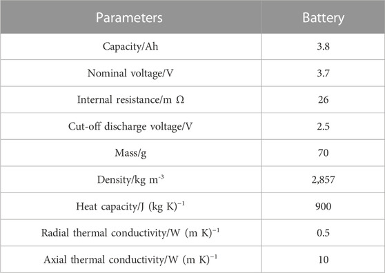
TABLE 1. Specifications of a 21,700 lithium-ion battery.
During the charging and discharging of the battery, lithium ions move back and forth between the cathode and anode in a reversible chemical reaction (Al-Zareer et al., 2019). During the charging process of a lithium-ion battery, lithium ions are released from the anode, flow through the electrolyte and are embedded in the cathode material through the diaphragm. At the same time, an equal amount of electrons with the same charge are transferred from the anode to the cathode through the external circuit. During discharging, lithium ions are released from the cathode material, flow through the electrolyte, and are embedded into the anode material via the separator. At the same time, an equal amount of electrons with the same charge are transferred from the cathode to the anode through the external circuit (Luo MY et al., 2022; Tan et al., 2022; Yang et al., 2022).
The equations for the anode, the cathode and the total battery reaction are as follows.
During the chemical reaction of a lithium-ion battery, the battery generates heat, which consists of four main parts, namely, the electrochemical heat of reaction Qr, the heat of polarization Qp, the Joule heat Qj and the side reaction heat Qs. The heat of side reactions is often neglected. Therefore, the total heat generation Qtotal of lithium-ion batteries can be expressed as follows (Angermeier et al., 2020):
2.2 Preparation of multilayer paraffin-graphite composite structures
Figure 1 shows the traditional heat dissipation structure of a battery filled with pure paraffin, which has a technical bottleneck of low thermal conductivity. Many scholars have actively explored the phase change heat dissipation structure of paraffin-graphite composite phase change materials to address the problem of insufficient thermal conductivity in the pure paraffin heat dissipation system. However, previous studies have focused on the mixed ratio of paraffin and graphite components, which could lead to problems such as graphite deposition and unstable thermal conductivity, and greatly affects the long-term operational reliability of battery thermal management. Therefore, this paper proposes a new arrangement structure for a multi-layer paraffin-graphite composite material, as shown in Figure 1.
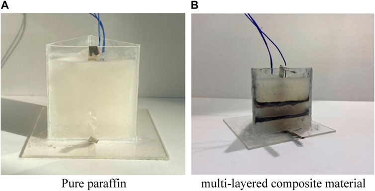
FIGURE 1. Different thermal management structures of the battery.
The preparation steps of the multilayer paraffin-graphite composite structures are as follows:
1) heating the paraffin wax to complete melting;
2) placing the battery at the center of a triangular container with a distance of 22 mm from the container walls;
3) pouring the melted paraffin wax into a container with a height of 100 mm, with a paraffin wax height of 20 mm;
4) placing a copper foil with a thickness of 1 mm on the surface of the paraffin wax;
5) filling graphite with a height of 3 mm on top of the copper foil;
6) placing another copper foil with a thickness of 1 mm on top of the graphite;
7) repeat steps 3) to 6) once;
8) finally, pouring the paraffin wax into a container, with a paraffin wax height of 40 mm. Assemble into the proposed multi-layer composite material arrangement structure.
Figure 2 shows a schematic diagram of the paraffin-graphite model. This structure can make full use of the thermal conductivity of graphite to fully transfer the heat of the battery to the interior of the paraffin, accelerate the phase change heat rate of the paraffin, and improve the thermal management performance of the battery.
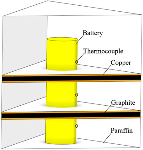
FIGURE 2. Schematic diagram of the paraffin-graphite model.
3 Experimental platform setup
3.1 Setup of the charge and discharge testing platform
The experiment mainly includes a computer, a charge-discharge tester (model: LANHE-CT5001B), a multi-channel temperature recorder (model: Ruixi CTR-380), a constant temperature box (model: Haida International HD-E702-1200), and a 21,700 battery.
3.2 Constant current discharge experiments
This paper conducted thermal performance tests on the two structures in Figure 1 under different environmental temperatures (15 °C, 20 °C) and different discharge rates (1°C, 2°C, 3°C, 4°C, 5°C). The physical parameters of the paraffin and the physical parameters of the graphite and copper are shown in Tables 2, 3, respectively.
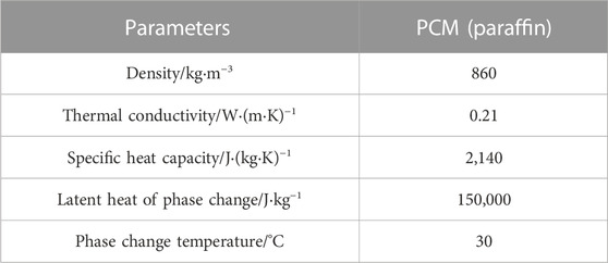
TABLE 2. Basic parameters of the PCM.
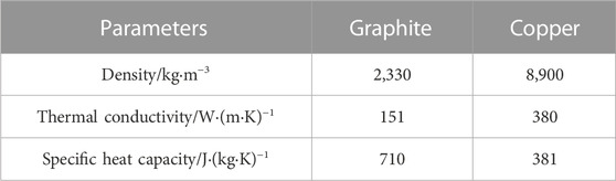
TABLE 3. Parameters of other materials.
The steps are as follows:
1) Charge the battery at a constant current of 0.1°C by using the charge-discharge tester until the charging voltage reaches 4.2 V, then end the charging process.
2) Place the battery with three thermocouples properly set up into the constant temperature box. Set the temperature of the constant temperature box to 15°C and let it stand for 2 h until the temperature readings of the three test points on the surface of the battery obtained by the temperature data logger are stable at 15°C.
3) Set the discharge rate by using the charge-discharge tester and discharge the battery until the voltage drops to 2.5 V, then end the discharge process.
4) Use the temperature data logger to record the temperature values of each test point on the battery during the discharge experiment.
5) Repeat the above operations by setting different temperatures and discharge rates.
4 Experimental results
Figure 3 gives the average temperature variation of the battery surface at 15°C for two different thermal management structures at a discharge rate of 1°C–5°C. The results show that the temperature rise is faster for the paraffin model and its surface temperature is higher than that of the paraffin-graphite model. Specifically, at discharge rates of 1°C–3°C, the temperature rise is slower in the paraffin-graphite model compared to the paraffin model, while the pure paraffin model has a clear upward trend at the end of the curve. The temperature rise rate is more pronounced for the paraffin model at a discharge rate of 4°C–5°C, while the paraffin-graphite model has a significantly lower temperature rise rate at the paraffin phase change temperature (30°C). These results indicate that graphite enhances the phase change effect of paraffin.
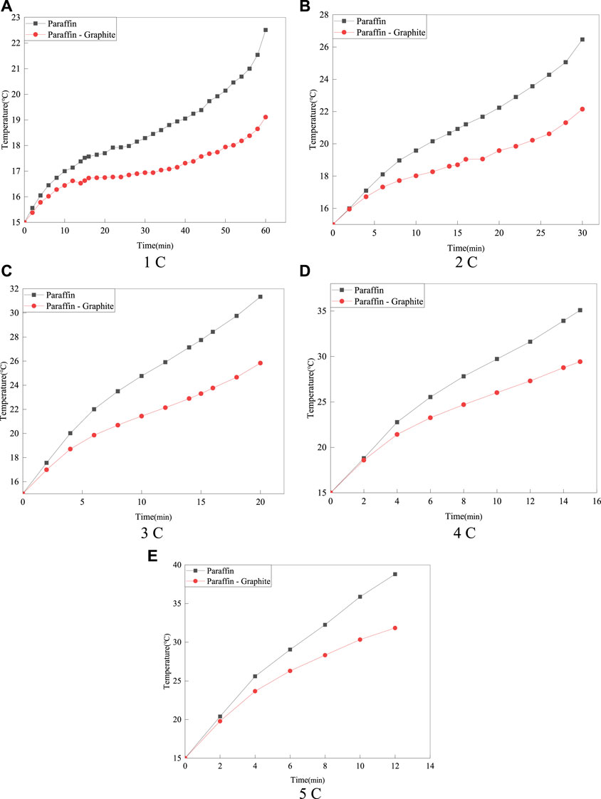
FIGURE 3. Average surface temperature of batteries with two different thermal management structures at an ambient temperature of 15°C.
Figure 4 shows the maximum temperature rise on the surface of the battery under different discharge rates for the paraffin model and the paraffin-graphite model. It can be seen that the average surface temperature of the battery in the paraffin-graphite model is lower than that in the paraffin model, and the temperature difference (ΔT) of the model increases with the increase of the discharge rate. At a discharge rate of 1°C, the maximum surface temperature (Tmax) of the battery in the paraffin model is 22.51°C, while that in the paraffin-graphite model is 19.11°C, with a ΔT of 3.4°C. At a discharge rate of 5°C, the Tmax of the paraffin model is 38.8°C, while that of the paraffin-graphite model is 31.84°C, with a ΔT of 6.96°C. It can be seen that with the increase of the discharge rate, the temperature increase of the paraffin model is greater. The ΔT at discharge rates of 1°C–5°C is 2.41°C, 3.26°C, 4.03°C, 5.64°C, and 7.23°C, respectively.
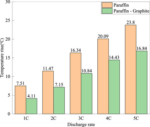
FIGURE 4. The highest temperature rise on the surface of the battery for the 15°C paraffin model and the paraffin-graphite model at different discharge rates.
Furthermore, to further verify the optimization effect of the optimized model, the average temperature on the surface of the battery for the paraffin model and the paraffin-graphite model at discharge rates of 1°C–5°C was compared again under the ambient temperature of 20°C.
Figure 5 shows the average temperature variation on the surface of the battery for the paraffin model and the paraffin-graphite model at discharge rates of 1°C–5°C under the ambient temperature of 20°C.
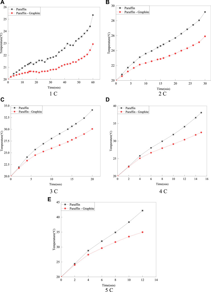
FIGURE 5. The average temperature on the surface of the battery for the 20°C paraffin model and the paraffin-graphite model.
As can be seen from Figure 5, at the ambient temperature of 20°C, the Tmax of the paraffin-graphite model is lower than that of the paraffin model. Compared with the ambient temperature of 15°C, at discharge rates of 1°C–3°C, the temperature rise of the paraffin model is smaller, and the temperature variation of the paraffin-graphite model is basically the same. At discharge rates of 4°C–5°C, the temperature variation is roughly the same as that at the ambient temperature of 15°C. It can be seen that the change in ambient temperature has little effect on the cooling effect of the model. However, as the discharge rate increases, the optimization effect of the paraffin-graphite model becomes more pronounced, especially when the battery temperature reaches the phase change temperature of 30°C. The highest temperature rise on the surface of the battery for the paraffin model and the paraffin-graphite model at different discharge rates is shown in Figure 6.
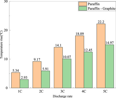
FIGURE 6. The highest temperature rise on the surface of the battery for the 20°C paraffin model and the paraffin-graphite model at different discharge rates.
From Figure 6, it can be seen that at an ambient temperature of 20°C, the ΔT at discharge rates of 1°C–5°C is 2.41°C, 3.26°C, 4.03°C, 5.64°C, and 7.23°C, respectively. Compared with an ambient temperature of 15°C, the relative reduction in ΔT is greater for discharge rates of 1°C–3°C, and the difference in ΔT is small for discharge rates of 4°C–5°C.
5 Numerical simulation for optimization
5.1 Grid independence verification
The tetrahedral unstructured mesh is generated by using ICEM in this study. In addition, to reduce the influence of the number of grids on the calculation results, we used five grids with the number of 79,137, 146,881, 271,601, 368,762, and 536,491 and verified the grid independence.
The change of highest temperature is small when the number of grids increases from 146,881 to 536,491. Therefore, to achieve a good balance between computational efficiency and accuracy, we choose the mesh consisting of 271,601 elements for numerical simulations.
5.2 Algorithm validation
To verify the reliability of the battery heating model and the effectiveness of the continuity, momentum, and energy equations of the PCM, the thermal characteristics of a battery with PCM is experimentally measured and numerically validated under 3°C discharge rate. In the experimental process, a thermostat is used to control the ambient temperature at 15°C. In addition, numerical simulation is used to verify the temperature results under the same environmental conditions and 3°C discharge rate. The comparison between the experimental results and the simulation results is shown in Figure 7.
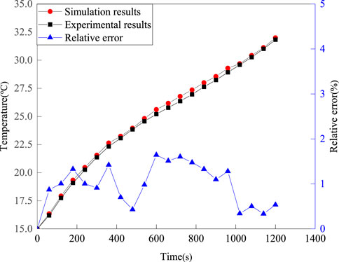
FIGURE 7. Comparison between the experimental results and the simulation results.
From Figure 7, it can be seen that the numerical results are consistent with the experimental results. The maximum relative error is 1.65%, which is kept within ±10%. Therefore, the experimental results confirm the correctness of the simulation method used in this study.
5.3 Composite layers optimization
This section describes the enhancement of heat transfer in multilayer composite structures by varying the number of graphite layers. The thermal characteristics of composite structures with 2, 4, 6, 8 and 10 graphite layers are investigated, which is shown in Figure 8.
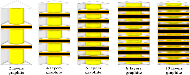
FIGURE 8. Geometric model for optimizing the number of layers in the composite structure.
Figure 9 shows the surface temperature distribution map of the battery at the end of discharge for different graphite layers and the 5°C discharge rate, with the outer wall in an insulated state.
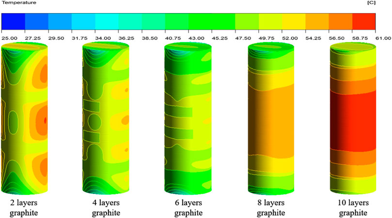
FIGURE 9. Temperature distribution of the battery with different graphite layers.
As shown in Figure 9, it can be observed that the surface temperature of the battery varies with the change of graphite layers. When the number of graphite layers varies from 2 to 6, increasing the number of graphite layers results in a better cooling effect and stronger temperature uniformity on the surface of the battery. However, when the number of graphite layers ranges from 6 to 8, as the number of graphite layers increases, the surface temperature of the battery gradually increases instead of decreasing. As can be observed, the surface temperature of the battery is the highest among all schemes when the number of graphite layers reaches 10. Figure 10 shows the average and maximum surface temperatures of the multi-layer composite structure battery under different discharge rates.
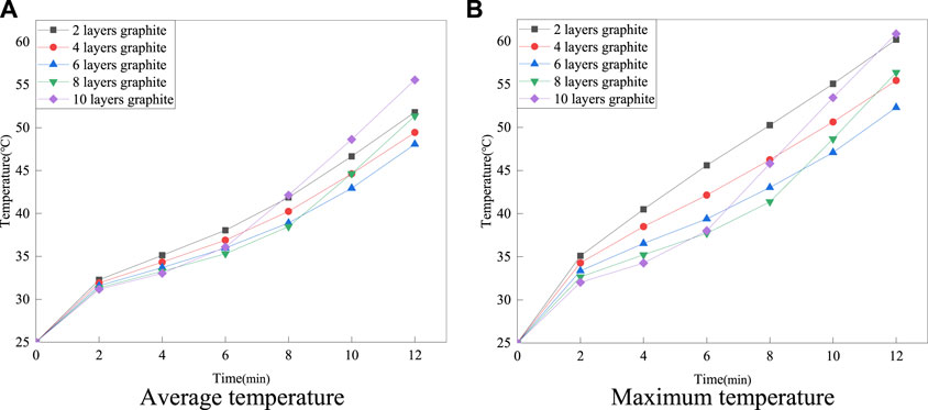
FIGURE 10. The average and maximum surface temperatures of the battery under a 5°C discharge rate.
According to Figure 10, when the number of graphite layers is 8 or 10, the average and maximum temperature of the battery tends to rise rapidly in the later stages of charging and discharging. In contrast, the 6-layer graphite structure shows the best thermal management performance. The main reason for the above phenomenon is that the graphite in the composite structure can transfer the heat from the surface of the battery to the inside of the paraffin wax quickly. As the graphite ratio increases and the paraffin ratio decreases, the heat absorption capacity of the paraffin decreases and may even no longer absorb heat through latent heat, but only through sensible heat, resulting in a rapid increase in the temperature of the paraffin. Therefore, this study indicates that an optimum ratio of multilayer paraffin and graphite composite structures exists to achieve the best thermal management performance.
5.4 Composite layer thickness optimization
Figure 11 shows thermally managed structures with graphite thicknesses of 0.25, 0.35, 0.5, 0.75, and 1 mm. The maximum and average surface temperatures of the battery for these structures were investigated analytically in the paper in order to find a relatively suitable graphite thickness.
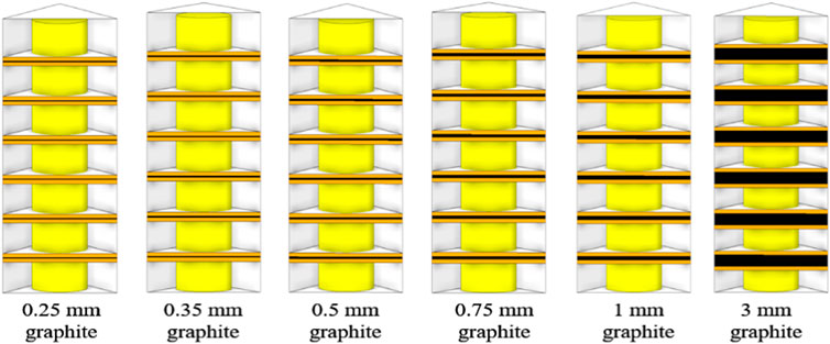
FIGURE 11. Geometric model for optimizing the thickness of composite structures.
Figures 12, 13 show the surface temperature distribution and section temperature distribution of the battery at the end of 5°C discharge for graphite thicknesses of 0.25–3 mm.
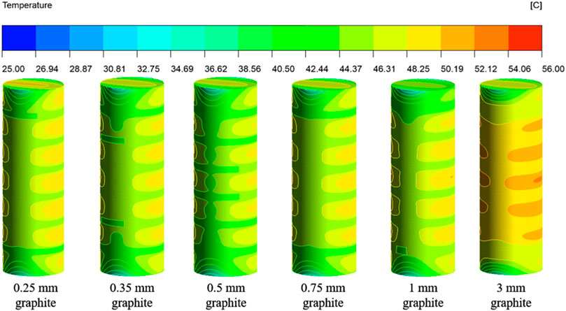
FIGURE 12. Temperature distribution of the battery with different graphite thicknesses.
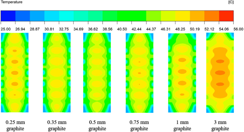
FIGURE 13. Section temperature distribution of the battery with different graphite thicknesses.
Figures 12, 13 show that the temperature rise between the maximum and initial temperature of the battery is 25.48°C, 24.89°C, 24.20°C, 25.03°C, 25.65°C and 27.30°C for graphite thicknesses of 0.25–3 mm, with temperature rise rates of 102%, 100%, 97%, 100%, 103% and 109% respectively. It can be seen that the temperature rise on the battery surface is minimal when the graphite thickness is 0.5 mm.
Figure 14 shows the average and maximum surface temperatures of the battery under 5°C discharge rate.
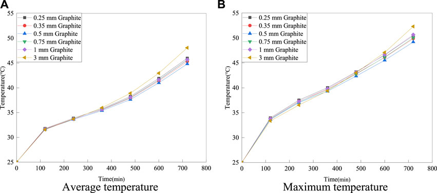
FIGURE 14. The average and maximum surface temperatures of the battery at 5°C discharge rate with different thicknesses of six-layer graphite structures.
As shown in Figure 14, the maximum surface temperatures of the battery are 50.47°C, 49.88°C, 49.19°C, 50.03°C, 50.65°C and 52.3°C when the graphite thickness is varied from 0.25 to 3 mm. The average temperatures of the battery are 45.96°C, 45.31°C, 44.81°C, 45.59°C, 45.68°C and 48.07°C, respectively. Therefore, a graphite thickness of 0.5 mm exhibits excellent thermal properties. The optimal solution obtained in this study is a six-layered structure made of multi-layered composite materials with a graphite thickness of 0.5 mm.
6 Conclusion
To solve the stability and uniformity problems in the thermal management of composite materials, this study proposed a new multilayer composite arrangement to cool Li-ion batteries. A battery thermal management testbed was established and the thermal performance of the battery was experimentally investigated. Emphasis is also placed on exploring the thermal behaviors of the system at different ambient temperatures and different charge and discharge rates. In addition, based on numerical simulation methods, this study also investigates the effect of the number of layers and thickness of graphite on the thermal management performance, providing the optimal battery thermal management structure. The main conclusions are as follows:
1) At an ambient temperature of 15°C, the multi-layered composite structure has a better cooling effect on the battery surface temperature than the pure paraffin structure under different discharge rates, and the effect is more pronounced with increasing discharge rate. At an ambient temperature of 20°C and a discharge rate of 5°C, the multi-layered composite structure reduced the temperature rise of the battery by 32.6%.
2) At discharge rates of 1°C–2°C, the thermal performance of the paraffin model and the paraffin-graphite model differed little between the two structures. However, at discharge rates of 3°C–5°C, especially when the battery surface temperature reaches 30°C, the temperature rise rate of the paraffin-graphite model decreases significantly, while the temperature rise rate of the pure paraffin model does not greatly change at this time.
3) The 6-layer graphite structure provides the best performance. It is worth noting that the average and maximum surface temperatures corresponding to the 8 and 10-layer graphite structures increase rapidly and may even exceed the permissible temperature of the battery later in the charging and discharging process.
4) When the graphite thickness is varied from 0.25 to 3 mm, the battery temperature is relatively low and the temperature uniformity is best for 0.5 mm graphite thickness. The best solution is therefore a multilayer composite structure with six graphite layers and a graphite thickness of 0.5 mm, which has an average surface temperature of 44.81°C.
Data availability statement
The original contributions presented in the study are included in the article/Supplementary Material, further inquiries can be directed to the corresponding author.
Author contributions
Formal analysis, funding acquisition, methodology, supervision, validation, visualization, writing—review and editing, YC and CK; data curation, software, writing—original draft, CK and JY; conceptualization, methodology, CK and CQ; methodology, resources, XY and CQ.
Conflict of interest
The authors declare that the research was conducted in the absence of any commercial or financial relationships that could be construed as a potential conflict of interest.
Publisher’s note
All claims expressed in this article are solely those of the authors and do not necessarily represent those of their affiliated organizations, or those of the publisher, the editors and the reviewers. Any product that may be evaluated in this article, or claim that may be made by its manufacturer, is not guaranteed or endorsed by the publisher.
References
Al-Zareer, M., Dincer, I., and Rosen, M. A. (2019). A novel approach for performance improvement of liquid to vapor based battery cooling systems. Energy Convers. Manag. 187, 191–204. doi:10.1016/j.enconman.2019.02.063
Angermeier, S., Ketterer, J., and Karcher, C. (2020). Liquid-based battery temperature control of electric buses. Energies 13 (19), 4990. doi:10.3390/en13194990
Baek, S. M., and Park, S. (2014). Thermal analysis of a battery cooling system with aluminum cooling plates for hybrid electric vehicles and electric vehicles. Transaction Korean Soc. Automot. Eng. 22 (3), 60–67. doi:10.7467/KSAE.2014.22.3.060
Behi, H., Karimi, D., Youssef, R., Suresh, P. M., Van, M. J., and Berecibar, M. (2021). Comprehensive passive thermal management systems for electric vehicles. Energies 14 (13), 3881. doi:10.3390/en14133881
Boomstra, M., Van, A. M., Geurts, B. J., Nazarychev, V. M., and Lyulin, A. V. (2022). Effects of branching and polydispersity on thermal conductivity of paraffin waxes. Int. J. Heat Mass Transf. 195 (3), 123192. doi:10.1016/j.ijheatmasstransfer.2022.123192
Fan, Y. W., Wu, H. W., and Wang, Z. H. (2022). Numerical investigation on lithium-ion battery thermal management utilizing a novel tree-like channel liquid cooling plate exchanger. Front. Energy Res. 10, 122143. doi:10.1016/j.ijheatmasstransfer.2021.122143
Feng, R., Huang, P., Tang, Z., He, Y., and Bai, Z. (2022). Experimental and numerical study on the cooling performance of heat pipe assisted composite phase change material-based battery thermal management system. Energy Convers. Manag. 272, 116359. doi:10.1016/J.ENCONMAN.2022.116359
Huang, J. J., and Yang, D. J. (2022). Improved system frequency regulation capability of a battery energy storage system. Front. Energy Res. 10, 904430. doi:10.3389/FENRG.2022.904430
Jarrett, A., and Kim, I. Y. (2011). Design optimization of electric vehicle battery cooling plates for thermal performance. J. Power Sources 196 (23), 10359–10368. doi:10.1016/j.jpowsour.2011.06.090
Li, Q., Cho, J., and Zhai, J. (2021). Optimization of thermal management system with water and phase change material cooling for Li-ion battery pack. Energies 14, 5312. doi:10.3390/EN14175312
Li, Y. H., Chen, Z. L., Feng, Y., Liu, M. N., Kang, C. Z., Yang, K., et al. (2023). A novel petal-type battery thermal management system with dual phase change materials. Int. J. Heat Mass Transf. 207, 123989. doi:10.1016/J.IJHEATMASSTRANSFER.2023.123989
Li, Y., Li, K., Xie, Y., Liu, B., Liu, J., Zheng, J., et al. (2021). Optimization of charging strategy for lithium-ion battery packs based on complete battery pack model. J. Energy Storage 37, 102466. doi:10.1016/j.est.2021.102466
Ling, Z. Y., Feng, X. N., Wang, Q. S., and Saw, L. H. (2022). Editorial: Advanced battery thermal management systems. Front. Energy Res. 10, 901083. doi:10.3389/FENRG.2022.901083
Liu, J., Ma, Q., and Li, X. (2022). Numerical simulation of the combination of novel spiral fin and phase change material for cylindrical lithium-ion batteries in passive thermal management. Energies 15 (23), 8847. doi:10.3390/en15238847
Luo, J., Gu, H., Wang, S., Wang, H., and Zou, D. (2022). A coupled power battery cooling system based on phase change material and its influencing factors. Appl. Energy 326, 119917. doi:10.1016/J.APENERGY.2022.119917
Luo, M. Y., Cao, J. H., Liu, N. H., Zhang, Z. H., and Fang, X. (2022). Experimental and simulative investigations on a water immersion cooling system for cylindrical battery cells. Front. Energy Res. 10, 803882. doi:10.3389/FENRG.2022.803882
Mohankumar, S. E., Harishbalaj, S., Satish, S. V., Kishore, V., Karthikeyan, K., and Naveenkumar, C. (2022). Computational investigation on phase change material based hybrid battery thermal management system for electric vehicle. Int. J. Veh. Struct. Syst. 14, 860–864. doi:10.4273/IJVSS.14.7.06
Patil, S. R., Lokavarapu, B. R., and Thaliyanveedu, H. K. (2023). Optimization of battery cooling system used in electric vehicles. J. Energy Storage 58, 106299. doi:10.1016/J.EST.2022.106299
Peter, V. (2022). Performance of a phase change material battery in a transparent building. Fluid Dyn. Mater. Process. 19 (3), 783–805. doi:10.32604/FDMP.2022.021962
Shi, H., Xu W, B., Zhu, X. L., Wang J, Y., Yang, K, J., Zou, Y., et al. (2022). A thermal-optimal design of lithium-ion battery for the container storage system. Energy Sci. Eng. 10, 951–961. doi:10.1002/ESE3.1076
Shi, H., Cheng, M. M., Feng, Y., Qiu, C. H., Song, C. Y., Yuan, N., et al. (2023). Thermal management techniques for lithium-ion batteries based on phase change materials: A systematic review and prospective recommendations. Energies 16 (2), 876. doi:10.3390/EN16020876
Tan, X., Liu, X., Wang, H., Fan, Y., and Feng, G. (2022). Intelligent online health estimation for lithium-ion batteries based on a parallel attention network combining multivariate time series. Front. Energy Res. 10, 844985. doi:10.3389/FENRG.2022.844985
Tang, X. W., Deng, J., Wu, Z. X., Li, X., and Wang, C. (2022). Experimental investigation on BN-based flexible composite phase-change material for battery module. Front. Energy Res. 10, 801341. doi:10.3389/FENRG.2022.801341
Wang, C. j., Zhu, Y. L., Fan, X. K., Qi, C., and Gao, F. (2021). Mathematical model for thermal behavior of lithium-ion battery pack under overheating. Appl. Therm. Eng. 191, 116894. doi:10.1016/j.applthermaleng.2021.116894
Wang, Y. F., Liu, D., Shen, Y., Tang, Y., Chen, Y., and Zhang, J. (2022). Adaptive balancing control of cell voltage in the charging/discharging mode for battery energy storage systems. Front. Energy Res. 10, 794191. doi:10.3389/FENRG.2022.794191
Wang, Z., Li, X., Zhang, G., Lv, Y., He, J., Luo, J., et al. (2017). Experimental study of a passive thermal management system for three types of battery using copper foam saturated with phase change materials. RSC Adv. 7 (44), 27441–27448. doi:10.1039/c7ra03963h
Yang, K. J., Li, Y. H., Yuan, J., Cheng, M. M., Liu, M. N., Kang, C. Z., et al. (2023). A thermal management system for an energy storage battery container based on cold air directional regulation. J. Energy Storage 61, 106679. doi:10.1016/j.est.2023.106679
Yang, R., Li, K., Xie, Y., Li, W., Qian, Y., Zhang, Y., et al. (2022). Thermal management of a 48 V lithium-ion battery pack by semiconductor refrigeration. Front. Energy Res. 9, 794438. doi:10.3389/FENRG.2021.794438
Yang, Y., Chen, L., Yang, L. J., and Du, X. Z. (2021). Numerical study of combined air and phase change cooling for lithium-ion battery during dynamic cycles. Int. J. Therm. Sci. 165, 106968. doi:10.1016/J.IJTHERMALSCI.2021.106968
Yi, F., E, J., Zhang, B., Zuo, H., Wei, K., Chen, J., et al. (2022). Effects analysis on heat dissipation characteristics of lithium-ion battery thermal management system under the synergism of phase change material and liquid cooling method. Renew. Energy 181, 472–489. doi:10.1016/J.RENENE.2021.09.073
Zhao, Y., Jin, L., Zou, B., Qiao, G., Zhang, T., Cong, L., et al. (2020). Expanded graphite – paraffin composite phase change materials: Effect of particle size on the composite structure and properties. Appl. Therm. Eng. 171, 115015. doi:10.1016/j.applthermaleng.2020.115015
Keywords: lithium-ion batteries, phase change materials, cooling, experimental studies, thermal management
Citation: Kang C, Yang J, Yuan X, Qiu C and Cai Y (2023) A novel multilayer composite structure based battery thermal management system. Front. Energy Res. 11:1187904. doi: 10.3389/fenrg.2023.1187904
Received: 16 March 2023; Accepted: 18 April 2023;
Published: 09 May 2023.
Edited by:
Nuray Kup Aylikci, İskenderun Technical University, TürkiyeReviewed by:
Dimberu G. Atinafu, Yonsei University, Republic of KoreaYuxun Ren, University of Maryland, College Park, United States
Copyright © 2023 Kang, Yang, Yuan, Qiu and Cai. This is an open-access article distributed under the terms of the Creative Commons Attribution License (CC BY). The use, distribution or reproduction in other forums is permitted, provided the original author(s) and the copyright owner(s) are credited and that the original publication in this journal is cited, in accordance with accepted academic practice. No use, distribution or reproduction is permitted which does not comply with these terms.
*Correspondence: Yufei Cai, bG9jeWZ2ZUBqdXN0LmVkdS5jbg==