 Xianggen Xu
 Tianliang Lin1,2*
- 1College of Mechanical Engineering and Automation, Huaqiao University, Xiamen, China
- 2Fujian Key Laboratory of Green Intelligent Drive and Transmission for Mobile Machinery, Xiamen, China
Owing to the high power consumption and limited control precision of traditional hydraulic drive winch systems, this study proposes hydraulic and electric-type energy recovery systems. The accumulator used in the hydraulic type has low energy density, which makes it difficult to store a large amount of energy. Meanwhile, the electric motor/generator used in the electric type cannot solve the secondary slip because of oil leakage, which leads to low controllability and high-power consumption under near-zero speed and high torque conditions. Thus, based on electric construction machinery with high-pressure, energy-dense electric energy storage units, this study proposes an electro-hydraulic composite drive winch and energy recovery system and control strategy for mobile cranes. Considering the good control characteristics of the electric motor/generator and the high-power density of the hydraulic accumulator, this hydroelectric composite drive and energy recovery system may solve the secondary sliding challenge and ensure large torque output at near-zero speed. A simulation model of the mobile crane is established to verify the feasibility of the proposed system and control strategy. The research results showed that the system is more efficient at recovering energy when the weight is lowered by a greater distance.
1 Introduction
With global warming, rising oil prices, and the energy crisis, the importance of energy saving and emission reduction has been gradually increasing in numerous guiding frameworks (Zhang et al., 2017; Liu, 2019). Construction machinery often has a large amount of negative load during movement. Reducing carbon emissions and implementing electrification to achieve energy saving and environmental protection are of current interest worldwide (Lin et al., 2020). The types of winch energy-saving drives are divided according to their components into hydraulic drive, electro-hydraulic composite drive, and direct electric motor/generator drive. Similarly, according to the energy storage components, winch energy recovery can be divided into hydraulic recovery, electric recovery, and composite recovery.
The winch systems of traditional construction machinery are primarily hydraulic drives. Central South University proposed an energy-saving system for the recovery of the potential energy of the main lowering winch of rotating drilling rigs, in which the secondary element hydraulic pump/motor was mechanically connected to the engine in a coaxial manner, and the accumulator recovered the residual potential energy (Zhu et al., 2018). Fang at Central South University designed a hybrid oil-electric winch system based on the hydraulic system for the main winch of rotary drilling rigs, in which the hydraulic motor/generator was used to recover the potential energy into electric energy stored in the supercapacitor when the main winch was lowered (Fang et al., 2012). Bolonne, at the University of Molétouvo, proposed a hybrid system for RTG cranes that included a lithium battery, a supercapacitor, and a diesel generator, in which the supercapacitor and lithium battery worked together to recover the crane's regenerable energy (Bolonne and Chandima, 2019). Kim at the Korean Classification Society proposed a hybrid system using diesel generators in combination with supercapacitors and lithium-ion batteries and assessed energy recovery into lithium batteries and supercapacitors under different operating conditions. The results showed that the system could significantly reduce harmful emissions (Kim et al., 2019). Corral-Vega of the University of Cadiz proposed an RTG drive scheme using a fuel cell as the energy source and a supercapacitor as the energy storage system. The simulation results demonstrated the high energy efficiency of the hybrid system. Direct-drive winches are primarily used in stationary machinery, such as tower cranes, shovels, and elevators. Huang from Beijing Jiaotong University proposed a supercapacitor-based power compensation and energy recovery system for mine hoisting equipment, in which the energy of the shaft grid and the potential energy of the shaft repair machine were stored in the supercapacitor through a converter (Huang Pu, 2015). The results showed that the system was more practical at obtaining power and the load was lower. Li from ZOOMLION researched a purely electric truck crane energy recovery device and system strategy in unplugged and plugged operation conditions, and verified the effectiveness of the crane winch energy recovery device and control strategy (Li et al., 2022). Research on electric winches has focused on electrical control devices (Premkumar and Manikandan, 2014; Kodkin and Anikin, 2020). A control device was used to prevent backlash due to slack in the traction component (Lee et al., 2019; Caporali, 2021). In addition, there are control algorithms that compensate for the loss of torque in the low-speed area of the motors (Li and Wang, 2019; Roman et al., 2021), and mechanical methods to improve the structure and stability to provide ordered coiling of strings, etc. Electro-hydraulic composite drive winch systems have used electric motor-hydraulic pumps/motors to supplement the composite drive and the power regeneration system. Liu of the Taiyuan University of Technology proposed an electro-hydraulic hybrid drive winch potential energy recovery system, which used an electric motor as the main drive to reduce throttling losses, combined with a hydraulic pump/motor and accumulator as the energy recovery unit. The results showed that the electro-hydraulic composite drive winch system had good energy recovery (Liu et al., 2022). Zhao of the Taiyuan University of Technology applied the composite electric motor-hydraulic pump/motor composite drive system to an elevator system, which recovered energy from the traction machine’s power generation state through the accumulator, and released the energy from the accumulator when the traction machine needed to be in the electric state for energy recovery (Zhao et al., 2016; Zhang et al., 2020). Wang Xthe at the Taiyuan University of Technology proposed a hybrid electro-hydraulic drive electric excavator hoist system, which utilized the engine as the main drive and the accumulator-hydraulic pump/motor as the auxiliary drive. The potential energy of the hoist system was mainly stored in the accumulator through the hydraulic pump/motor when the hoist system was lowered. The energy was released by the accumulator when it was lifted (Wang et al., 2020). The hydraulic pump/motor and the electric motor worked together to complete the lifting. The simulation results showed that the system reduced the power consumption by approximately 30% compared to the traditional system. Zhang of the Dalian University of Technology proposed a composite electro-hydraulic drive hoist system, in which the speed was controlled by a hydraulic system and the torque was controlled by an electric motor. The hydraulic motor was connected to the two ends of the bobbin to drag the load together. The results showed that the system energy recovery efficiency was approximately 60% (Zhang, 2019).
To recover the potential energy of the mobile crane winch system and reduce engine pollution, considering the good control characteristics of the electric motor/generator and the high power density of the hydraulic accumulator, this study proposes a hydro-electric composite drive and energy recovery system to solve the challenge of secondary sliding and ensure the large torque output at near-zero speed. A control strategy is also proposed to integrate energy recovery and regeneration for the proposed composite winch system.
2 Working principles of the winch system
The scheme of the proposed entity electro-hydraulic composite drive winch system is shown in Figure 1. The system mainly contains an electrical component, a hydraulic drive component, and a mechanical drive component.
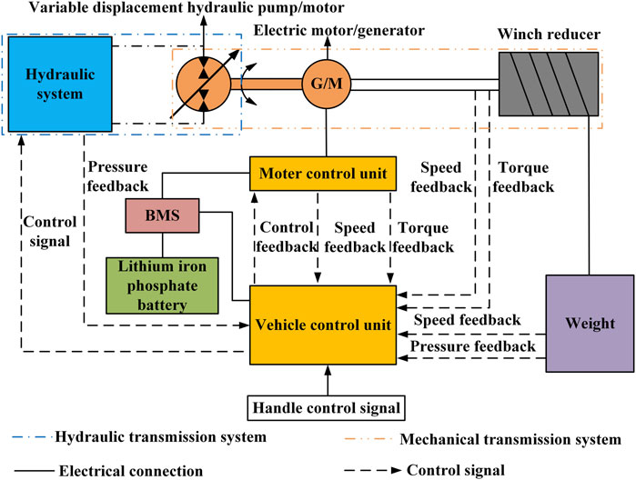
FIGURE 1. Schematic diagram of the proposed winch system.
2.1 Electric drive component
The pressure signal from the hydraulic system, the speed and torque signal from the motor controller, and the artificially desired weightlifting speed signal are collected by the vehicle control unit (VCU). The control unit in the hydraulic system, the electric motor controller unit (MCU), and the lithium battery management system (BMS) receive the control signals from the VCU via the controller area network (CAN) bus and input and output (IO) port. The closed-loop enables cooperative control in multiple quadrants of the electric motor/generator-variable displacement hydraulic pump/motor output speed, angle, torque, and other parameters. The weight is driven to lift and lower to achieve the desired movement.
2.2 Hydraulic drive component
The hydraulic drive component is shown in Figure 2. In addition to storing energy, the high-pressure and low-pressure accumulators provide hydraulic energy to the variable displacement hydraulic pump/motor. Each 2-position, 2-way electromagnetic valve receives control signals from the VCU depending on the different working conditions. Hydraulic oil in both the high-pressure and low-pressure accumulators is transferred to the variable displacement hydraulic pump/motor. The oil is pressurized or depressurized and then returned to the high-pressure and low-pressure accumulators via the 2-position, 2-way electromagnetic valve to complete the energy recovery. The differential pressure between the two ends of the variable-displacement hydraulic pump/motor changes continuously with changes in the pressure of the high-pressure and low-pressure accumulators. The variable-displacement hydraulic pump/motor receives control signals from the VCU to change the displacement to meet the required output torque, while the high-pressure and low-pressure accumulators satisfy the pressure conditions.
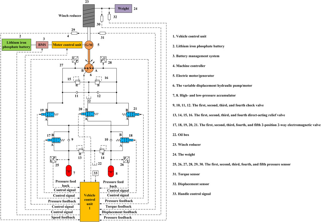
FIGURE 2. Hydraulic schematic of the winch system.
2.3 Mechanical drive component
The mechanical drive component consists of coaxial mechanical coupling among the variable-displacement hydraulic pump/motor, electric motor/generator, and winch reducer. The weight is wound onto the winch reducer using a wire string. The winch reducer is driven by the electric motor/generator-variable-displacement hydraulic pump/motor controlled by the VCU. The weightlifting and lowering motion is determined by the VCU.
3 Control strategy and implementation process of the winch system
3.1 Analysis of the winch system control strategy
The signals of the pressure, displacement, torque, and SOC are input to the VCU through various sensors. The weightlifting and lowering motion mode differs depending on the load weight, the pressure difference between the high-pressure and low-pressure accumulators, the low-pressure accumulator pressure, and the SOC. During the movement of the weight, the speed of the electric motor/generator is directly controlled by the handle opening. The displacement of the variable-displacement hydraulic pump/motor adapts itself to the speed. When a constant torque output of the variable-displacement hydraulic pump/motor is required, the VCU sends a corresponding control signal to each 2-position, 2-way electromagnetic valve and variable-displacement hydraulic pump/motor. The flow direction of the oil circuit and the displacement of the displacement hydraulic pump/motor change to achieve a constant torque output of the variable-displacement hydraulic pump/motor. The electric motor/generator for adaptive torque compensation and control strategy are shown in Figure 3, where YP is the handle opening (divided into positive and negative sides); Ymin is the positive and negative minimum handle opening; Ymax is the positive and negative maximum handle opening; SOC is the state of charge of the lithium battery; Smax is the maximum SOC value when potential energy recovery is performed; F is the negative load weight; Fmin is the negative load weight when switching from purely electric motor/generator drive to electro-hydraulic composite drive; D17, D18, D19, D20, and D21 correspond to the first, second, third, fourth, and fifth 2-position, 2-way electromagnetic valve, respectively; Δp and Δpmin are the differential pressure and minimum differential pressure between the high-pressure and low-pressure accumulators, respectively; p1 is the high-pressure accumulator pressure; p2 is the low-pressure accumulator pressure; p2min is the minimum threshold pressure of the low-pressure accumulator; and pBA is the differential pressure between B-port pressure pB and A-port pressure pA of the variable-displacement hydraulic pump/motor, i.e., the differential pressure between the two ends of the variable displacement hydraulic pump/motor.
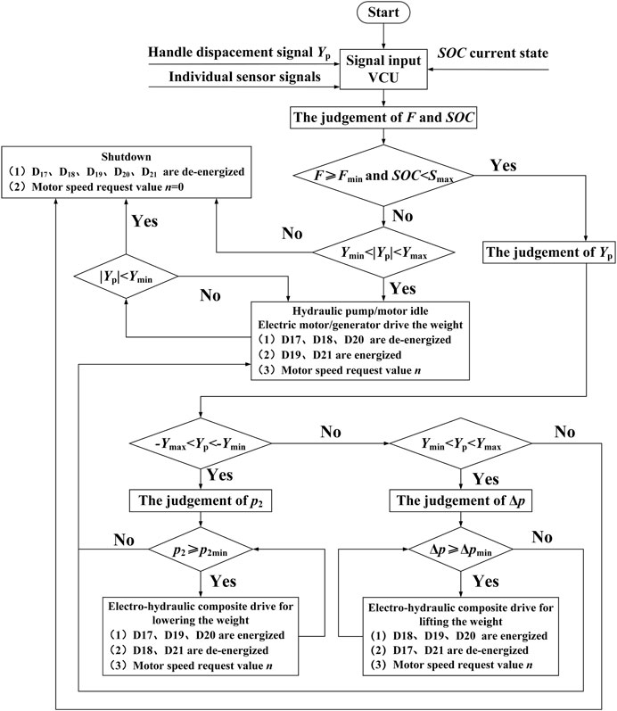
FIGURE 3. Control strategy for the winch system.
According to the aforementioned, the control strategy is as follows:
(1) If the load weight satisfies
(2) If the load weight satisfies
(3) If the load weight satisfies
3.2 Implementation process for the winch system
If the load is light (
If the load is heavy (
If the load is heavy (
When the winch must be stopped during the weight-lowering process, the handle opening should be reduced to below the minimum threshold. All the 2-position, 2-way electromagnetic valves are controlled in the de-energized state. The electric motor/generator is controlled by the VCU in the blocked condition to stop the movement of the weight. The first check valve, the second check valve, and all four direct-acting relief valves work as required.
The system makes full use of the high energy density of the electrical energy storage unit and the good control characteristics of the electric motor/generator. The system also provides a solution to the problem of secondary sliding of heavy loads as well as the low energy density of the accumulator. The proposed closed hydraulic system using the accumulator-variable displacement hydraulic pump/motor can achieve high power density and high torque output at near-zero speed and solve the problem of high energy consumption of the electric motor/generator drive winch and part of the energy loss in the balance and multiple directional control valves.
4 Winch system modeling and simulation model
4.1 Winch system modeling
After the load weight F and the desired lifting and lowering speed v have been determined, the output power of the electric motor/generator-variable displacement hydraulic pump/motor is determined using Eq. 1.
where P, n, and T are the output power, speed, and output torque of the electric/generator-variable hydraulic pump/motor, respectively.
The output power P includes two components: output torque T and output speed n. For the electric motor/generator-variable-displacement hydraulic pump/motor, the required output torque T is determined by the load weight F, the diameter of winch reducer reel D, and the winch reducer transmission ratio r, as shown in Eq. 2.
In the case of the electric motor/generator-variable-displacement hydraulic pump/motor, the desired velocity n can be determined by the desired lift and lowering velocity v of the weight, the diameter of the winch reducer reel D, and the winch reducer transmission ratio r, as shown in Eq. 3.
The variable-displacement hydraulic pump/motor is designed to deliver a constant proportional torque. The displacement V of the variable displacement hydraulic pump/motor can be determined by ∆p, as shown in Eq. 4
where V is the displacement of the variable displacement hydraulic pump/motor, and k is the displacement influencing factor, the value of which is directly related to the output power assumed by the artificially desired variable displacement hydraulic pump/motor. T/k denotes the amount of output torque that must be assumed by the variable-displacement hydraulic pump/motor.
After the electric motor/generator speed has been controlled at the desired value and the displacement of the variable-displacement hydraulic pump/motor has been calculated, the required flow rate of the high-pressure accumulator q1 and low-pressure accumulator q2 can be calculated by Eq. 5.
where q is the high-pressure and low-pressure accumulator flow rate.
The maximum pressures of the high-pressure and low-pressure accumulators are limited by the setting pressures of the first and second direct-acting relief valves, respectively. The setting pressures of the third and fourth direct-acting relief valves are determined by the system operating pressure. The first check valve, the second check valve, the first charge check valve, and the second charge check valve are not set to an initial pressure. Each 2-position 2-way electromagnetic valve has a fully open and a fully closed state. In the fully open state, the flow rate restriction or pressure drop at the inlet and outlet of the valve is as small as possible. Therefore, the differential pressure between the high-pressure and low-pressure accumulators can be approximated as that of the two ends of the variable displacement hydraulic pump/motor. The hydraulic system may not be capable of delivering constant proportional power due to the capacity limitations of the high-pressure and low-pressure accumulators. Thus, movement of the weight requires the electric motor/generator alone.
4.2 Winch system simulation model
According to the scheme presented in Figure 1 and the control strategy illustrated in Figure 3, the simulation model of the electro-hydraulic composite drive winch system is shown in Figure 4. The main components of the simulation model are the hydraulic system model, the signal control system model, and the mechanical system model.
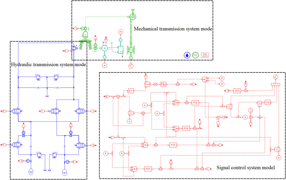
FIGURE 4. Simulation model of the winch system.
The heavy-load mass, the light-load mass, the winch reduction ratio r, the reel diameter, and the maximum lifting and lowering velocity of the weight are defined as 3 t, 1 t, 55.2, 0.44 m, and 1.5 m/s respectively.
Calculated using Eq. 1, the maximum output powers required by the electric motor/generator-variable-displacement hydraulic pump/motor for heavy and light loads are 45 kW and 15 kW, respectively.
Calculated using Eq. 2, the maximum output torques required by the electric motor/generator-variable-displacement hydraulic pump/motor for the heavy and light loads are 120 N∙m and 40 N∙m, respectively.
Calculated using Eq. 3, the maximum weight-lowering speed required by the electric motor/generator-variable-displacement hydraulic pump/motor is 3,594 r/min.
The Δpmin is controlled at around 1.2 MPa. The minimum k is set at 5/3, which means that 3/5 of the torque required by the system must be carried by the variable-displacement hydraulic pump/motor. The maximum V required by the variable-displacement hydraulic pump/motor for the heavy and light loads can be calculated using Eq. 4 as 450 mL/r and 150 mL/r, respectively. Therefore, the variable-displacement hydraulic pump/motor with a maximum V of 500 mL/r is used in the system.
The rated power, the rated torque, and the rated speed of the electric motor/generator should be greater than the values calculated above. The initial state of charge of the lithium battery is set to 90%, and the capacity of the lithium battery is set to 6.5 Ah.
The main technical parameters required for the simulation of the electro-hydraulic composite drive winch system are shown in Table 1.

TABLE 1. Main simulation parameters of the winch system.
5 System simulation analysis
The simulation analysis focuses on the dynamic characteristics of the lifting cycle of the weight at different variable-displacement hydraulic pump/motor output proportional torques and initial pressures of the high-pressure accumulator, as well as the energy recovery efficiency of the system during the lowering of the weight.
5.1 Dynamic characteristics of the weight under different conditions
The cycle time in the simulation is set to 12.5 s, where 0–6 s is the lifting condition, 6 s–6.5 s is the stop condition, and 6.5 s–12.5 s is the lowering condition. The expected lifting and lowering velocity is 0.2 m/s. The speed of the electric motor/generator-variable-displacement hydraulic pump/motor is controlled by the PID at 480 r/min. The dynamic characteristics of the weight lifting and lowering are studied under a different initial pressure of the high-pressure accumulator and output torque of the variable-displacement hydraulic pump/motor, respectively. As the Δp can be approximated as pBA, it is set to Δpmin (1.2 MPa) when the weight is lifting (
Owing to the advantages of good oil and gas isolation, high specific volume, and tightness, airbag accumulators are used for both high-pressure and low-pressure accumulators in the system. The high-pressure accumulator is set to 5 L with a pre-charge pressure of 2 MPa, while the low-pressure accumulator is set to 10 L with a pre-charge pressure of 0.5 MPa. The relationship between the volume V1 of the accumulator gas chamber and pressure is shown in Eq. 6.
where W is constant and m is the state index varying between 1 and 1.4.
The trend of the accumulator state parameters during the charging and discharging of the accumulator can be obtained from Figure 5. Where the charging and discharging process curves do not coincide, the general expansion process of the gas (discharging process) is faster than the compression process (charging process).
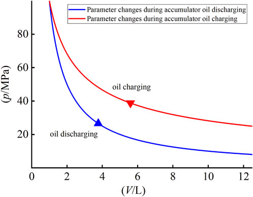
FIGURE 5. Variation in accumulator state parameters.
5.1.1 Different initial pressures of the high-pressure accumulator
The purpose of this study was to investigate the dynamic characteristics of weight lifting and lowering under different initial high-pressure accumulator pressures from p3 to 4 MPa, 5.5 MPa, and 7 MPa. The initial pressure p2 is the same 1.5 MPa under different conditions. Moreover, the lift condition is such that
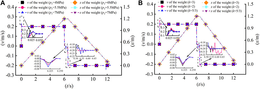
FIGURE 6. Dynamic characteristics of the system under different conditions. (A) Different p3. (B) Different k.
When the weight is in the lifting condition (0–6 s), the lower the p3, the smaller the initial Δp and pBA ends of the variable-displacement hydraulic pump/motor. In cases with the same required torque and speed, according to Eq. 4; Eq. 5, the larger the initial V required, the larger the initial q1. Accordingly, a larger q will flow into the low-pressure accumulator with the same initial p2 (1.5 MPa). For the system with lower p3, as shown in Figures 5, 7A and Eq. 6 show that p2 rises faster. The faster that pBA falls, the faster that V will rise. As shown in Figure 7C, the q1 will rise faster, the flow rate into the corresponding high-pressure and low-pressure accumulators will also rise, and the pressure will rise faster. As shown in Figures 7B, D, the faster the differential pressure reaches Δpmin (1.2 MPa), the faster the variable-displacement hydraulic pump/motor will be in an idle state without output torque, and the motor/generator will output torque separately during the lifting condition.
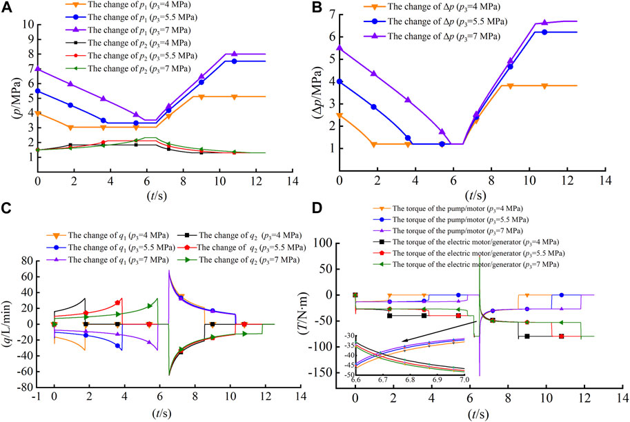
FIGURE 7. Pressure and flow rate characteristic of the system at different p3. (A) High-pressure and low-pressure accumulator pressure variation. (B) Differential pressure variation of the high-pressure and low-pressure accumulators. (C) Flow rates of the high-pressure and low-pressure accumulators. (D) Variation in the output torque of the electric motor/generator-variable hydraulic pump/motor.
When the weight is in the stop condition (6 s–6.5 s), the load weight is lifted from 1 t to 2 t at 6.2 s and changed from the stop condition to the lower condition at 6.5 s. As shown in Figures 6A, 7B, D and Eq. 10, no sliding down of twice the weight occurs owing to the instantaneous high torque provided by the electric motor/generator and variable-displacement hydraulic pump/motor. The Δp is always 1.2 MPa during this period.
When the weight is in the lowering condition (6.5 s–12.5 s), for the system with a different p3, the Δp is initially the same at 1.2 MPa. When the required torque and speed are the same, according to Eq. 4; Eq. 5, the required V and q2 are also the same. For the system with higher p3, as shown in Figure 7B shows that in the lowering condition, the faster that the Δp rises, the faster the pressure difference between the two ends of the variable-displacement hydraulic pump/motor rises, and the faster that V will fall. As shown in Figure 7C, q2 will fall faster. It is reasonable to say that in the system with a higher p3, the slower that the pressure of the corresponding high-pressure accumulator will rise and the slower that the pressure of the low-pressure accumulator will fall during the lowering process. For the system with a higher p3, the initial p1 and p2 are higher. Combined with Figure 5; Figure 7B; Eq. 6 show that in the system with the higher p3, the faster the ∆p and the pressure difference between the two ends of the variable-displacement hydraulic pump/motor will rise during the entire lowering process. As shown in Figures 7A,D, the faster the p2 reaches p2min (1.3 MPa), the faster the variable-displacement hydraulic pump/motor will be in an idle state without output torque, and the motor/generator will output torque separately during the lowering condition.
5.1.2 Different variable-displacement hydraulic pump/motor output proportional torque
For
When the weight is in the lifting condition (0–6 s), the initial pressures of the high-pressure and low-pressure accumulators are the same for systems with different k values. The initial Δp is the same. The initial differential pressure between the two ends of the variable-displacement hydraulic pump/motor is the same. For the system with larger proportional torque output, in the case of the same required speed according to Eq. 4, the larger the required initial V, the larger the initial q1. According to Eq. 5 and as shown in Figure 5 and Eq. 6, the faster the p1 falls and p2 rises, the faster the pressure difference between the two ends of the variable-displacement hydraulic pump/motor falls and the faster the V will rise. As shown in Figure 8C, the q1 will rise faster. The corresponding q2 and p2 will also rise faster. As shown in Figures 8B, D, the faster the differential pressure reaches Δpmin (1.2 MPa), the faster the variable displacement hydraulic pump/motor will be in an idle state without torque output and the motor/generator will separately output torque during the lifting condition.
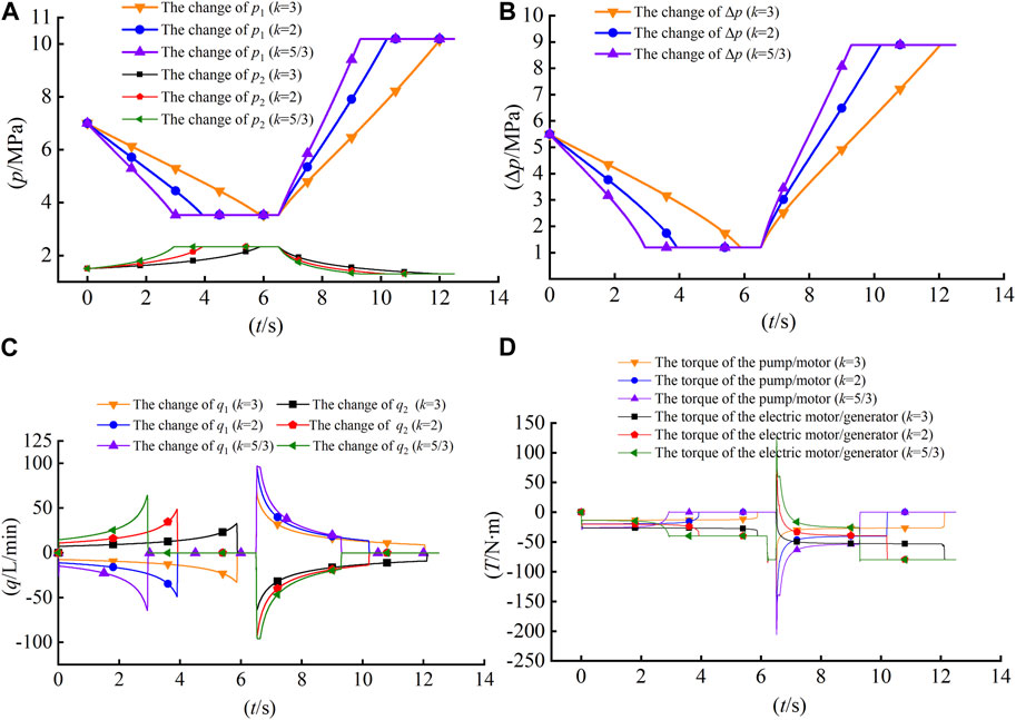
FIGURE 8. Pressure and flow rate characteristics of the system at different k values. (A) High-pressure and low-pressure accumulator pressure variation. (B) Differential pressure variation for high-pressure and low-pressure accumulators. (C) Flow rate for high-pressure and low-pressure accumulators. (D) Variation of the output torque of the electric motor/generator-variable-hydraulic pump/motor.
When the weight is in the stop condition (6 s–6.5 s), the load weight is lifted from 1 t to 2 t at 6.2 s and changed from the stop condition to the lower condition at 6.5 s. As shown in Figures 6B, Figures 8B,D and Eq. 10, no sliding down of twice the weight occurs owing to the instantaneous high torque provided by the electric motor/generator and variable-displacement hydraulic pump/motor. The Δp is always 1.2 MPa during this period.
When the weight is in the lowering condition (6.5 s–12.5 s), for the different k in the system, the initial ∆p is always 1.2 MPa. For the system with larger k, in the case of the same required speed according to Eq. 4; Eq. 5 shows that the required initial V and initial q2 are larger. Figure 5 and Eq. 6 show that the faster the p2 falls and the p1 rises, the faster pBA rises, and the faster the V will fall. As shown in Figure 8C, the q2 will fall faster; thus, it is reasonable to say that the higher the k, the slower the corresponding p1 will rise and the corresponding p2 will fall during the lowering process. The system with the higher proportional torque output of the variable-displacement hydraulic pump/motor during the whole lower process can still rely on its higher torque required to maintain the q at a higher level even when the q falls, as shown in Figure 8C. The combination of Figures 5, 8A, B, and Eq. 6 shows that the higher the proportional torque of the variabledisplacement hydraulic pump/motor outputs during the whole lower process, the faster p1 rises, the faster p2 falls, and the faster Δp rises. As shown in Figures 8B, D, the faster that p2 reaches p2min (1.3 MPa), the faster the variable-displacement hydraulic pump/motor will be in an idle state without output torque, and the motor/generator will output torque separately during the lowering condition.
5.2 Analysis of the efficiency of the system energy recovery
The energy recovery efficiency of the winch system is discussed in terms of the power of the high-pressure accumulator, the power of the low-pressure accumulator, the power of the electric motor/generator, and the power consumption of the lowering weight. The energy can be obtained by integrating the corresponding power of each component. The system is in the recovery mode of the electro-hydraulic composite drive during the descent, i.e.,
The power of the high-pressure accumulator P1 and the low-pressure accumulator P2 are determined using Eq. 7 and Eq. 8.
The power of the electric motor/generator P3 can be calculated from Eq. 9.
where U and I represent the busbar voltage and current of the electric motor/generator, respectively. The electric motor/generator is in the electric motor state when
The power of the lowering weight P4 can be determined by the weight lowering height s and F, as shown in Eq. 10.
The energy recovery efficiency of the system P5 is determined using Eq. 11.
After setting
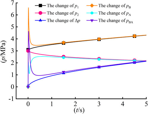
FIGURE 9. Variations in the pressures of the accumulators and hydraulic pump/motor.
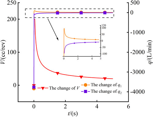
FIGURE 10. Variation in the displacement of the hydraulic pump/motor and the flow rate of the accumulators.
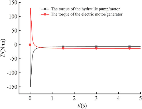
FIGURE 11. Variation in the torque of the hydraulic pump/motor and electric motor/generator.
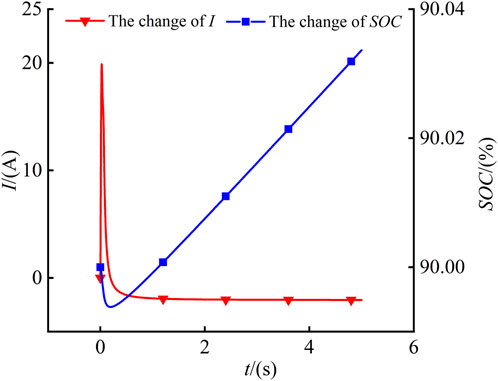
FIGURE 12. Variation in the busbar current of the electric motor/generator and the SOC of the battery.
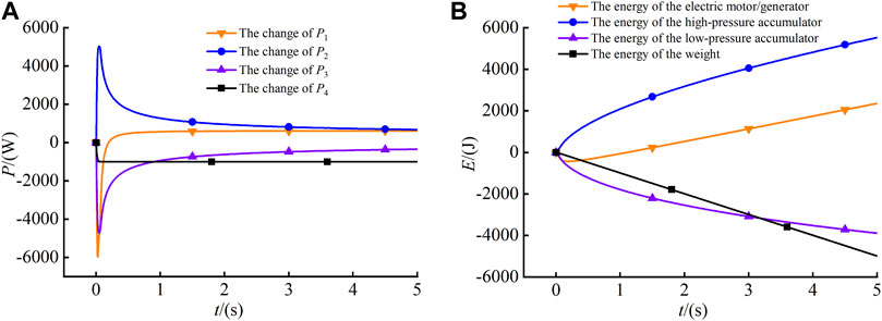
FIGURE 13. Variation in the power and energy of each component. (A) Variation in the power of each component. (B) Variation in the energy of each component.
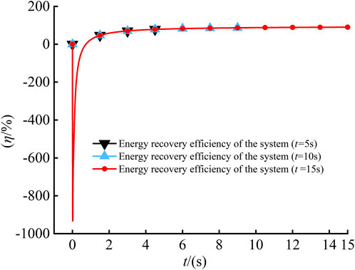
FIGURE 14. Energy recovery efficiency at different distances of weight descent.
6 Conclusion
To recover the gravitational potential energy and avoid secondary sliding, this study proposed an electro-hydraulic composite drive winch and energy recovery system for mobile cranes. The problems of secondary sliding of the weight and the limited energy recovery of the accumulator can be solved effectively by the high energy density of the lithium batteries and the good control characteristics of the electric motor/generator. The problem of high energy consumption of the electric motor/generator drive winch and most of the energy consumption of the liquid drive winch in the balance and multiple directional control valves can be alleviated by instantaneous high-power density and large torque output at the near-zero speed of the accumulator-variable displacement hydraulic pump/motor.
The feasibility of the control strategy of the electro-hydraulic composite drive winch and potential energy recovery system was verified through the study of the dynamic characteristics of the weight lifting and lowering under different conditions. We studied the pressure variations of the high-pressure and low-pressure accumulators (p1 and p2), as well as the pressure difference (Δp), flow rate (q), and output torque of the electric motor/generator-variable displacement hydraulic pump/motor (T). When p3 or k is at different values in this electro-hydraulic composite drive winch system, the weight lifting and lowering dynamic characteristics differ.
The energy recovery efficiency of the electro-hydraulic composite drive winch and potential energy recovery system control strategy was higher for weights lowered a greater distance. Although the energy recovery efficiency of the system was high in the final results, the magnitude of the final recovery efficiency could be influenced by changing the initial pressure and volume of the high-pressure and low-pressure accumulators as well as the fixed voltage of the lithium battery. The specific energy recovery efficiency is for reference only and must be considered in conjunction with the actual situation. The system control strategy is mainly based on the detection of load weight F, battery SOC, high-pressure and low-pressure accumulator pressure, etc., to determine the drive mode of the weight. The electro-hydraulic composite drive mode can reasonably use the motor speed active control to achieve variable-displacement hydraulic pump/motor adaptive speed. Automatic adjustment of the displacement of the variable-displacement hydraulic pump/motor is used to actively control the torque and, thus, achieve adaptive torque compensation of the electric motor/generator.
The energy recovery efficiency of the system in this study may vary considerably under different initial conditions. The basis for the high efficiency of the energy recovery of the system is the selection of suitable initial conditions in the actual working process. The efficiency of the energy recovery is not considered in this system when the initial pressure (p1 and p2) and volume of the high-pressure and low-pressure accumulators and the performance parameters of the lithium battery are changed. The results of this study lay a foundation for further experimental research.
7 Research ethics
The study does not involve animal or human subjects and does not contain identifiable human data.
Data availability statement
The raw data supporting the conclusion of this article will be made available by the authors, without undue reservation.
Author contributions
XX and TL contributed to the direction of the research content, study design, manuscript writing, data processing, and data analysis. HR and TG contributed to the literature searches and data collection. ZL and CM were mainly responsible for data analysis and project management. All authors contributed to the article and approved the submitted version.
Funding
This work was supported by the National Key Research and Development Program (2020YFB2009900), the National Natural Science Foundation of China (Grant No. 52275055), Key Projects of the Natural Science Foundation (Grant No. 2021J02013).
Acknowledgments
We thank all the authors for completing the study and acknowledge the valuable comments and constructive suggestions of the editor and reviewers.
Conflict of interest
The authors declare that the research was conducted in the absence of any commercial or financial relationships that could be construed as a potential conflict of interest.
Publisher’s note
All claims expressed in this article are solely those of the authors and do not necessarily represent those of their affiliated organizations, or those of the publisher, the editors, and the reviewers. Any product that may be evaluated in this article, or claim that may be made by its manufacturer, is not guaranteed or endorsed by the publisher.
References
Bolonne, S. R. A., and Chandima, D. P. (2019). Sizing an energy system for hybrid Li-ion battery-supercapacitor RTG cranes based on state machine energy controller. Ieee Access 7, 71209–71220. doi:10.1109/access.2019.2919345
Caporali, R. P. L. (2021). Anti-sway method for reducing vibrations on a tower crane structure. Int. J. Nonlinear Sci. Numer. Simul. 24, 171–184. doi:10.1515/ijnsns-2021-0046
Corral-Vega, P. J., Garcia-Trivino, P., and Fernandez-Ramirez, L. M. (2019). Design, modelling, control and techno-economic evaluation of a fuel cell/supercapacitors powered container crane. Energy 186, 115863. doi:10.1016/j.energy.2019.115863
Fang, X., Zhao, H., and Liu, P. (2012). Simulation study of main winch system geopotential energy recovery in rotary driller. Eng. J. Wuhan Univ. 45, 241–245+272.
Huang Pu, H. (2015). Study of ultracapicator-based power compensation and energy Rocovery system for mine lifting equipment. Beijing: Beijing Jiaotong University.
Kim, K., An, J., Park, K., Roh, G., and Chun, K. (2019). Analysis of a supercapacitor/battery hybrid power system for a bulk carrier. Appl. Sciences-Basel 9. doi:10.3390/app9081547
Kodkin, V. L., and Anikin, A. S., (2020) The reflection mode of the moment loads by an asynchronous electric drive with vector control and the features of this mode in the rotation drive of the tower crane", in: International Ural Conference on Electrical Power Engineering, 22-24 September 2020, Russia.
Lee, J.-G., Yeo, H.-K., Jung, H.-K., Kim, T.-K., and Ro, J.-S. (2019). Electromagnetic and thermal analysis and design of a novel-structured surface-mounted permanent magnet motor with high-power-density. Iet Electr. Power Appl. 13, 472–478. doi:10.1049/iet-epa.2018.5322
Li, K., and Wang, Y. (2019). Maximum torque per ampere (MTPA) control for IPMSM drives using signal injection and an MTPA control law. Ieee Trans. Industrial Inf. 15, 5588–5598. doi:10.1109/tii.2019.2905929
Li, X., Cao, S., Luo, M., and Sun, L. (2022). Design and control strategy of energy recovery device for pure electric vehicle crane. Constr. Mach. Equip. 53, 104–108+113.
Lin, T., Lin, Y., Ren, H., Chen, H., Chen, Q., and Li, Z. (2020). Development and key technologies of pure electric construction machinery. Renew. Sustain. Energy Rev. 132, 110080. doi:10.1016/j.rser.2020.110080
Liu, H., Quan, L., Hao, Y., Huang, J., Li, Y., and Liu, Y. (2022). Fabrication of superhydrophobic coating based on waterborne silicone-modified polyurethane dispersion and silica nanoparticles. Chin. Hydraulics Pneumatics 46, 22–29. doi:10.3390/polym15010022
Liu, J. (2019). China's renewable energy law and policy: A critical review. Renew. Sustain. Energy Rev. 99, 212–219. doi:10.1016/j.rser.2018.10.007
Premkumar, K., and Manikandan, B. V. (2014). Adaptive neuro-fuzzy inference System based speed controller for brushless DC motor. Neurocomputing 138, 260–270. doi:10.1016/j.neucom.2014.01.038
Roman, R.-C., Precup, R.-E., and Petriu, E. M. (2021). Hybrid data-driven fuzzy active disturbance rejection control for tower crane systems. Eur. J. Control 58, 373–387. doi:10.1016/j.ejcon.2020.08.001
Wang, X., Ge, L., Zhao, B., Hao, Y., Quan, L., and Mu, X. (2020). Energy efficiency characteristics of cable shovel lifting system driven by hydraulic-electric hybrid system. Trans. Chin. Soc. Agric. Mach. 51, 418–426. [In Chinese].
Zhang, H. (2019). Research on energy saving technology of hydraulic truck crane. Dalian: Dalian Ligong University. [master's thesis].
Zhang, J., Zhao, B., Hao, Y., Yu, H., Wang, J., Lei, A., et al. (2020). Pluripotent stem cell-derived CAR-macrophage cells with antigen-dependent anti-cancer cell functions. Chin. Hydraulics&Pneumatics 13, 153–160. [In Chinese]. doi:10.1186/s13045-020-00983-2
Zhang, Y.-J., Peng, Y.-L., Ma, C.-Q., and Shen, B. (2017). Can environmental innovation facilitate carbon emissions reduction? Evidence from China. Energy Policy 100, 18–28. doi:10.1016/j.enpol.2016.10.005
Zhao, B., Quan, L., and Hao, Y. (2016). Research of operating characteristics and energy efficiency of traction elevator with hybrid electric-hydraulic drive. J. Mech. Eng. 52, 192–198. doi:10.3901/jme.2016.04.192
Keywords: winch system, engineering machinery, secondary slip, mobile crane, electro-hydraulic composite drive, energy recovery efficiency
Citation: Xu X, Lin T, Ren H, Guo T, Li Z and Miao C (2023) Research on electro-hydraulic composite drive winch and energy recovery system for mobile crane. Front. Energy Res. 11:1187558. doi: 10.3389/fenrg.2023.1187558
Received: 16 March 2023; Accepted: 01 June 2023;
Published: 19 June 2023.
Edited by:
Yang Yang, Yangzhou University, ChinaReviewed by:
Wang Hongliang, Changzhou Institute of Technology, ChinaWeixuan Jiao, Yangzhou University, China
Leilei Ji, Jiangsu University, China
Copyright © 2023 Xu, Lin, Ren, Guo, Li and Miao. This is an open-access article distributed under the terms of the Creative Commons Attribution License (CC BY). The use, distribution or reproduction in other forums is permitted, provided the original author(s) and the copyright owner(s) are credited and that the original publication in this journal is cited, in accordance with accepted academic practice. No use, distribution or reproduction is permitted which does not comply with these terms.
*Correspondence: Tianliang Lin, bHRsa3hsQDE2My5jb20=