 Shuli Hong
 Weiyu Lu2
94% of researchers rate our articles as excellent or good
Learn more about the work of our research integrity team to safeguard the quality of each article we publish.
Find out more
ORIGINAL RESEARCH article
Front. Energy Res. , 30 June 2023
Sec. Process and Energy Systems Engineering
Volume 11 - 2023 | https://doi.org/10.3389/fenrg.2023.1184687
This article is part of the Research Topic Optimal Design and Efficiency Improvement of Fluid Machinery and Systems View all 18 articles
A two-dimensional vortex model is introduced in this paper in order to understand the characteristics of the shedding vortex in a blade-divergent passage and to mitigate or suppress it by appropriate methods. The performance of this model under the influence of three typical external factors is studied, namely, the main flow extrusion effect, viscous effect, and transport effect. Based on the analysis, a negative circulation unsteady flow control technique is proposed to compensate for the viscous effect, which is known as NCFC. Numerical simulation is performed to verify the effectiveness of the NCFC method. The results show that the NCFC method is superior to the conventional unsteady flow control for improving the performance of the blade-divergent passage in most cases. In addition, there is an optimum injection to suppress the shedding vortex with NCFC, which is about 0.2% of the main flow mass, and NCFC shows to be more efficient than conventional flow control in weakening the shedding vortex. Furthermore, NCFC can effectively inhibit separation flow and is shown to be insensitive to the injection flow mass. Finally, the NCFC method is highly recommended to adapt to the fact that the working conditions often change in practice.
The compressor is an important part of the Brayton cycle system, which is widely used in military and civilian fields such as aircraft engines, gas turbines, and distributed energy systems. The development of these devices requires the compressor to have a higher pressure ratio. The improvement of the pressure ratio of the compressor can be achieved in two ways: one is to increase the linear speed of rotation, and the other is to increase the flow angle. The method of increasing the linear rotational speed to improve the compressor capacity has little room for manoeuvre due to the level of material technology. Therefore, the other way to improve the performance is to increase the flow angle of the compressor. The optimization design of the blade profile is the main way to improve the flow angle, but the accompanying large diffuser makes it easy to cause flow separation in the blade passage, which makes it difficult to significantly improve the performance of the compressor further.
Among these flow separations, the blade suction surface separation flow is one of the most typical complex separation flows in high-load compressors, which will lead to negative factors such as increasing losses, passage blockage, reducing efficiency, and even inducing stall or surge, which will seriously affect the stable operating range of the compressor (Gbadebo et al, 2005; Lei, 2006; Choi et al, 2008; Likiewicz et al, 2020). Therefore, based on the in-depth understanding of the separation flow mechanism of the blade suction surface, it is necessary to introduce an effective flow control technology to suppress or weaken the flow separation in the compressor so that the compressor can maintain a high load while having a wide stable working range and efficiency, which is one of the key research directions in the compressor field at present.
Up to now, a considerable amount of research has focused on the separation flow at the blade suction surface of the compressor or cascade, and some appropriate flow control techniques have also been used to achieve good results. Gbadebo et al (2008) used a suction flow control method with an inlet mass flow rate of 0.7% to weaken the flow separation at the blade suction surface, and the cascade experiment proves that this flow control method can increase the blade load and improve the average static pressure. Braunscheidel et al (2008) developed a synthetic jet system and applied it to the suction surface of stator blades in a low-speed axial compressor. The results showed a loss reduction of 5.5 percent for the entire passage. Yang et al (2021) studied the cascade-separated flow by numerical simulation and experimental methods. The flow control method of suction was used to control the separated flow at the blade suction surface, and various suction schemes were compared, including the suction position and suction capacity. The results showed that a suitable suction method was very effective in controlling the separated flow. Feng et al (2022) studied the influence of the separated vortex on the blade suction surface of the compressor and its propagation process to the adjacent blades at high angles of attack. It was found that the unsteady effect produced by the separated vortex had an important influence on the stable operation of the compressor, and it was considered that the study of the separated vortex was very important for predicting the stall of the compressor. Tang et al (2020) proposed a diagram to carry out the blade design by resisting the unfavourable pressure gradient near the suction surface and to determine a correct operating range.
Although these studies have made some progress and achieved good results, there are still many problems that cannot be solved. For example, the selection of the control location is very specific, whether the flow control is suction type or jet type (Matejka et al, 2008; Yousefi and Saleh, 2015; Chen et al, 2017; Abdolrahim et al, 2019). Now, the general conclusion is that the control position near the separation point is the best choice, but there is no final conclusion on such issues as where or within what range the specific position falls or what effect the change of position will have on the control effect. As another example, it is generally believed that the mechanism of suction is to eliminate the low-energy flow in the boundary layer (Liesner et al, 2010; Ma et al, 2018), and the jet can achieve the excitation effect by the principle of increasing momentum (Giorgi et al, 2015; Chen et al, 2022). However, the further problem is how these control methods specifically affect the coherent structures of turbulence and how they are coupled to the flow field to play a role in the separation/shedding vortex. At present, these issues are not well understood. In addition, the current implementation of effective control methods is often based on a specific operating condition. If the working conditions are constantly changing, it is questionable whether these control measures are still effective and, if so, how they should be changed. As a result, it is difficult to come to a definitive conclusion about such things as the amount of control, the incidence/suction angle, and the frequency of control of the unstable means. An important source of these problems is that the interaction between different control methods and vortex structures at the mechanism level is not clear enough.
Theoretical research usually refines the dominant features of some typical vortex structures and summarises their internal laws or physical mechanisms to obtain some general conclusions. Orszag (1971) used the Orr–Sommerfeld equation based on the N-S equation to analyse the stability of plate shear flow. The Stuart–Landau model was established to analyse the flow in the critical state (Stuart, 1958; Stuart, 1967), and it was later used to analyse the shedding vortex of the cylinder (Thompson and Gal, 2004). To analyse the unsteady motion of the shedding vortex of a cylinder, the van der Pol equation was used (Skop, 1995) and developed into the van der Pol-Duffen equation to explain the flow control mechanism (Marzouk et al, 2007). A simplified cross-directional motion model (SCDM) similar to the van der Pol-Duffen equation was developed by our team (Huang et al, 2017) to analyse cascade separation flow and its flow control mechanism. These theories and models were further developed and used in subsequent research studies (Theofilis, 2003; Akhtar et al, 2009; Ku et al, 2015). In summary, the theoretical research on the blade suction surface separation flow is relatively deficient and incomplete compared with the numerical and experimental research, which causes difficulties in the in-depth understanding of the separation/shedding vortex and the adoption of appropriate methods to suppress it.
In order to improve and complete the theoretical understanding of the blade suction separation/shedding vortex and to lay the foundation for adopting an accurate, effective, and relatively universal flow control method, a two-dimensional vortex model is introduced in this paper. The main contents of this paper can be divided into the following three parts: first, the blade-divergent passage and its main internal flow structures are introduced, on the basis of which a two-dimensional vortex model for the blade suction shedding vortex is introduced (Section 2, Section 3). Then, three typical external factors are studied individually depending on the model, and an unsteady flow control concept based on negative circulation is proposed (Section 4, Section 5). Finally, numerical simulation is carried out to verify the effectiveness of the negative circulation flow control (NCFC) method in comparison with the conventional unsteady flow control (Section 6).
In this study, a blade-divergent passage established by our team is used. A blade is placed at the corner of the passage, which is derived from a stator blade provided by China Gas Turbine Establishment (CGTE), as shown in Figure 1. The inlet width is 34.3 mm, and the outlet width is 55.5 mm. The blade chord length is 80.0 mm. More details can be found in Hong and Huang (2017) and Zhu et al (2015). In our previous study, an unsteady jet flow control driven by the pressure difference between the blade suction and pressure surfaces was investigated. Here, we compare it with our new flow control method in the following section through numerical simulation.
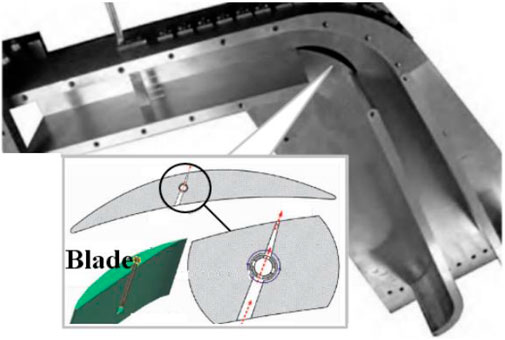
FIGURE 1. Structure diagram of the blade-divergent passage.
Two-dimensional numerical calculation is adopted for the blade-divergent passage by large eddy simulation (LES). The length of the entire calculation domain is about 6.25 times chord length in total, about 1.25 times chord length at the inlet, and 4 times chord length at the outlet. The Reynolds number is about 1.8 × 10⁵, and the non-dimensional wall distance y+ ≈ 1. The grid height of the first wall layer is set to be 0.001 mm. Figure 2 shows the computational gird of the blade-divergent passage (the bypass flow is useful only for flow control). By comparing the relationship between the flow rate and the inlet Mach number with the number of calculation grids, the results no longer change with the number of grids when the number of grids exceeds 80,000, as shown in Figure 3. Therefore, for an uncontrolled blade-divergent passage, a grid of 90,000 numbers is used. A velocity inlet of magnitude 35 m/s is given for the blade-divergent passage, corresponding to the Mach number Ma ≈0.1 referred to in the experiment. The outlet is set to be a pressure outlet with a static pressure of 0 Pa (gauge pressure). The solid wall is adiabatic with no slip conditions. The time step is 1 × 10⁻⁵ s with 20 iterations per time step. Based on the results of this paper, an average CFL number of 0.45 can be obtained, which is lower than the value of 1.0 suggested by Ferziger and Peric (2002) and Balduzzi et al (2016a). Furthermore, according to Balduzzi et al (2016b), each time step for a rotating impeller should be between 0.135° and 0.405°. If the time step of 1 × 10⁻⁵ s used in this paper corresponds to this angular range, the impeller speed would exceed 800,000 RPM, which would satisfy most impeller calculation needs. By comparing the shedding vortex frequency, relative total pressure loss coefficient, average pressure, and other parameters under different conditions, it is shown that the experimental and numerical simulation results are in good agreement (Zhu et al, 2015; Hong and Huang, 2017). Therefore, the numerical simulation adopted in this paper has a certain degree of credibility.
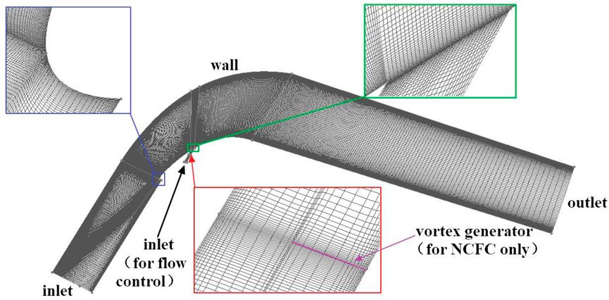
FIGURE 2. Computational grid of the blade-divergent passage.
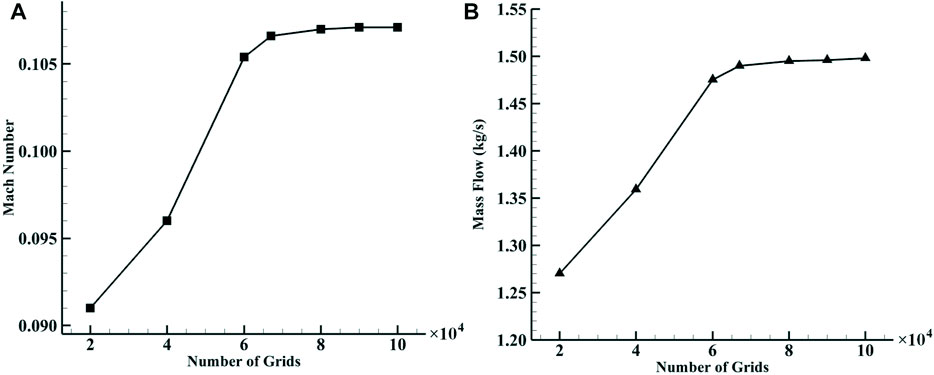
FIGURE 3. Variation of the main aerodynamic parameters of the uncontrolled flow field with the number of grids. (A) Variation of the inlet Mach number with the number of grids. (B) Mass flow variation with the number of grids.
Basically, the flow field is considered to have entered a state of unsteady convergence when the average mass flow rate and other channel parameters remain unchanged, and the instantaneous parameters show periodic fluctuations. We select the flow fields in one period after unsteady convergence (the shedding vortex frequency f0 ≈ 266 Hz (Zhu et al, 2015; Hong and Huang, 2017)) for analysis.
Figure 4 shows the vorticity distribution of the flow field at different times in one shedding vortex period. It can be seen that under the influence of the unfavourable pressure gradient and the curvature, the airflow begins to become unstable on the curved wall due to the K-H instability, causing the vortex layer to roll up and form a small-scale shedding vortex (shown by the dotted line at 1/6T). The curled vortex extends in the curved channel from 2/6T to 4/6T. At 5/6T, a new shear layer instability occurs (shown with the red dotted line at 5/6T). Finally, it spreads further downstream along the main flow.
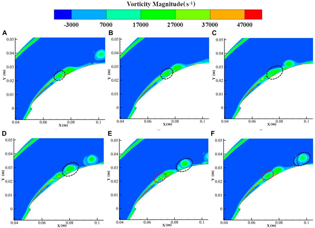
FIGURE 4. Flow structures in the blade-divergent passage without control. (A) 1/6T. (B) 2/6T. (C) 3/6T. (D) 4/6T. (E) 5/6T. (F) 6/6T. (i/6T means i/6 of one shedding vortex period).
It can also be seen from Figures 4, 5 that the profile of the shedding vortex at the blade suction surface is elliptical. The irregularity of the ellipse is due to the coupling of small-scale vortices to the shedding vortex. When we extract the dominant vortex structure using special technology, such as the dynamic mode decomposition (DMD) method, the regularity of the elliptical vortex becomes clear (Hong and Huang, 2017). This is the main reason why we introduce an elliptical vortex model instead of a circular vortex, which is usually used.
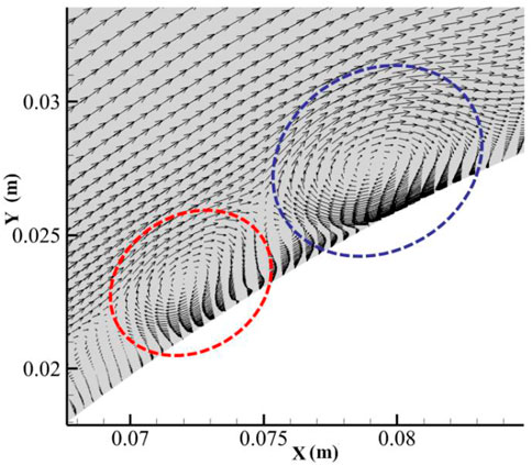
FIGURE 5. Velocity vector at 3/6T.
As we have presented the details of the two-dimensional vortex model (Hong et al, 2022), we will only give a brief introduction to the model’s principles and results. The region where vorticity is concentrated in a two-dimensional inviscid flow field is called the vortex patch. For example, the vortex core of a Rankine vortex is the simplest circular vortex patch often used by researchers to analyse vortex structures. In general, the boundary shape of a vortex patch of any shape should change continuously as the vortex patch moves. There is a special case: an elliptical vortex patch with uniform vorticity will rotate on itself at a constant angular velocity and remain unchanged; this type of vortex is called a Kirchhoff elliptical vortex. The constant angular velocity is expressed by the following formula:
where a and b are the long and short axes of the ellipse, respectively. From the previous CFD results, the core region of the blade suction shedding vortex is very close to the Kirchoff elliptical vortex. Therefore, our research is based on the elliptical vortex.
Based on the elliptical vortex model, we can divide the flow field inside the blade-divergent passage into the following two parts: inside the ellipse, the vorticity is known and its velocity field is determined; and the outside of the ellipse is equivalent to an elliptical column affected by the passage flow. Finally, the two parts are combined to give the total velocity field.
First, the governing equation of the stream function outside the elliptical vortex is
where r2 = x2 +y2, Vb is a point velocity on an ellipse surface, n is the unit outer normal vector, and s is the surface arc length measured counterclockwise. On the other hand, if we express the normal velocity with a stream function, then the normal velocity has the following form:
Comparing Eqs 3, 4 and after integration, the surface stream function expression can be obtained as
Then, we use elliptic coordinates (η, ξ) and assume that the velocity on the boundary of the elliptical vortex is close to the main flow velocity U due to the influence of the viscous force to obtain the stream function expression on the border
where the elliptic focus is c2 = a2−b2. Finally, when we combine the aforementioned surface boundary condition (6) with the governing Eq. 2, the condition that the velocity at infinity is 0, and the consideration that the elliptical vortex has a circulation Γ = πabω, that is, the vortex flux passing through the cross-sectional area of the ellipse; the external stream function can be expressed as
where the superscript “o” in the formula means external, ξo is the elliptic coordinate ξ on the border, and ω is vorticity.
Second, the governing equation of the stream function inside the elliptical vortex is
We choose the stream function of the form
where the superscript “i” in the formula means internal, and A and B are undetermined coefficients to be solved. According to the aforementioned equations and the continuity of the normal and tangential velocity components at the boundary between the inner and outer flows, we can obtain the final internal stream function
The purpose of this section is to use the model introduced in the previous section to analyse the blade suction shedding vortex characteristics under some typical loads. In general, the flow in the passage is quite complex; even for the dominant coherent vortex structure, such as the shedding vortex, there are many factors acting on it. These complex factors are intertwined, making it difficult for us to identify which factors play a leading role or which factors trigger the phenomena we observe macroscopically. Therefore, our idea is to separate these factors and only consider what happens when a simple factor acts behind the vortex. In this part, we have analysed three typical factors of action in the blade-divergent passage, which we call the “main flow extrusion effect”, the “main flow and wall viscous effect,” and the “transport effect,” respectively. Other factors can also be analysed and studied in this way.
The description of the mainstream extrusion is shown in Figure 6. The dotted line in the figure represents a virtual extrusion. The low energy flow near the wall begins to break away from the wall and form a large-scale shedding vortex due to the effects of wall viscosity and back pressure. At the same time, the main flow turns into the shedding vortex due to the influence of the curved channel and causes a certain degree of extrusion, which will affect the structure of the shedding vortex.
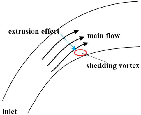
FIGURE 6. Schematic representation of the main flow extrusion effect.
To analyse and simplify this squeezing action, we set the coordinate origin at the centre of the ellipse; the x-axis and y-axis coincide with the long axis and short axis of the ellipse, respectively; and the extrusion action passes through the coordinate origin, so its corresponding stream function can be simplified as follows:
where e is the strain rate strength that is determined here by the strength of the passage flow.
According to the superposition principle of harmonic functions, after the strain effect is applied to the original external stream function, the new external stream function becomes
where the subscript “ee” means the extrusion effect. Continuity conditions for the stream function and tangential velocity on the ellipse boundary are satisfied, which provides
The aforementioned two equations can be simplified to
So the ratio of the strain rate to vorticity is
whose value range is from −1/2 (ε + 1) to −1/2 (1/ε + 1), where ε = a/b is the axial ratio of the ellipse. From this, it can be seen that the extrusion effect of the main flow on the shedding vortex is opposite to the direction we set earlier, indicating that the extrusion of the passage flow actually plays a role in the stretching effect. When the fluid separates from the wall, the vortex will instead compress the main flow passage. The main flow seems to exert an entrainment effect on the shedding vortex. Meanwhile, we can conclude that the expansion of the shedding vortex has a range from −1/2 (ε + 1) to −1/2 (1/ε + 1) relative to the shedding vortex, and this value depends on the axial ratio of the ellipse. In short, the main stream has a suction effect on the shedding vortex, and its strength depends on the shedding vortex itself.
The viscous effects include the fluid viscosity and the solid wall viscosity, as shown in Figure 7. During the formation of the backflow, the shedding vortex forms a relative motion with the main flow and the solid wall. The viscous acceleration effect of the main flow and the viscous stagnation effect of the wall are approximately equivalent to the formation of an additional circulation around the shedding vortex. As in the previous section, we set the coordinate origin at the centre of the ellipse and use a point vortex model for the additional circulation. The corresponding current function is
where the subscript “ve” means the viscous effect. In addition, according to the continuity condition, we obtain
and
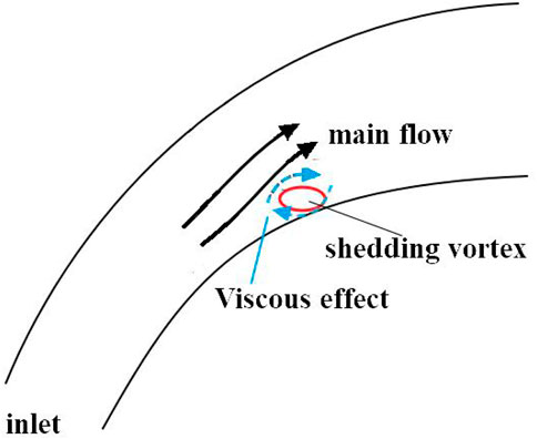
FIGURE 7. Schematic representation of the viscous effect.
We can multiply Eq. 18 by 2 and add it to Eq. 19 to eliminate the second term to get
By analysing the aforementioned equation, we can get the maximum and minimum values of Γo/ω:
The aforementioned expression gives the range of Γo/ω, which is the range of values that the mainstream viscous force and wall friction can affect the shedding vortex. It can be seen that the viscous force depends on the long and short axes of the elliptical vortex. Further analysis shows that the minimum value of Γo/ω can only be less than 1 when both the long axis a and the short axis b are less than 1. In addition, in most cases, Γo/ω is greater than 1. In other words, in most cases, when the viscous force acts on the shedding vortex, its influence will even exceed that of the shedding vortex itself. Only when the scale of the shedding vortex is small can the effect of the viscous force be less than that of the vortex itself. This may be due to the small scale of the vortex, which makes the range of action of the viscous force not large enough.
As mentioned previously, the movement of the shedding vortex trajectory is the result of many factors, but from the perspective of lateral displacement, the effect of movement is more direct compared to other factors. The transport effect is discussed in this section, as shown in Figure 8.
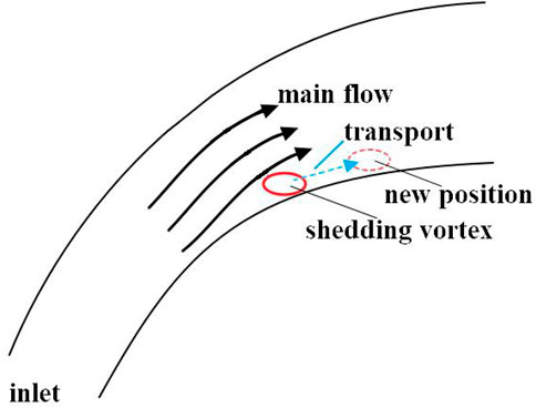
FIGURE 8. Schematic representation of the transport effect.
Now, assuming that the shedding vortex is constant, we can write the stream function corresponding to the translational action as
where A, B, and C are constants determined by the strength of the passage flow. Since our analysis takes the long axis of the elliptical vortex as the x-axis, a simpler stream function can be written as
Then, we replace B with e for notation consistency with the previous analysis. The external stream function becomes
where the subscript “te” means the transport effect. Using the continuity condition, we obtain
and
The aforementioned two equations can be combined as
Finally, we get the ratio of the strain rate to vorticity
whose absolute minimum value is ab/2 (2b+a). This reflects the influence of the passage flow on the shedding vortex trajectory. Unlike the extrusion and viscous effects, the transport effect has no upper limit. In addition, relative to the original vortex, the minimum effect depends on both the long and short axes of the shedding vortex. This is equivalent to creating a flow condition to generate a shedding vortex in the blade-divergent passage, and if the passage flow is strong, its influence on the shedding vortex will also increase.
As mentioned previously, it can be seen that the intensity ratio of the transport effect to the shedding vortex has only a minimum value, which means that the effect is a necessary condition to affect the shedding vortex. Therefore, from a flow control point of view, we are not willing to spend much energy on controlling this effect. For the main flow extrusion effect, if we take a conventional ellipse with axis ratio ε = 2, the maximum intensity ratio of the extrusion effect to the shedding vortex can be obtained from Eq. 16 as 1/3. Comparing this value with the minimum value of Γ0/ω (Eq. 22), which is greater than 1 in most cases, we can conclude that the influence of the extrusion effect on the shedding vortex will be much greater than that of the viscous effect. Therefore, an appropriate flow control method that we adopt should be to weaken or better inhibit the viscous effect. Here, we propose that the jet flow control should include an action opposite to the viscous effect to offset it, i.e., to produce an action opposite to the point vortex we introduced earlier, which we call NCFC technology.
Figure 9 shows a jet flow control device based on NCFC technology. A vortex generator can be set in the jet channel to produce a negative circulation effect. In order to eliminate the influence of the jet inlet on the control effect and to create fully developed vortices in the bypass tube, we have increased the length of the bypass tube accordingly. It is worth mentioning that the NCFC technology may also be applicable to unsteady suction flow control methods. Although the unsteady control method will use the principles of frequency locking, phase locking, and some other mechanisms (Huang et al, 2017), NCFC technology may further improve its efficiency.
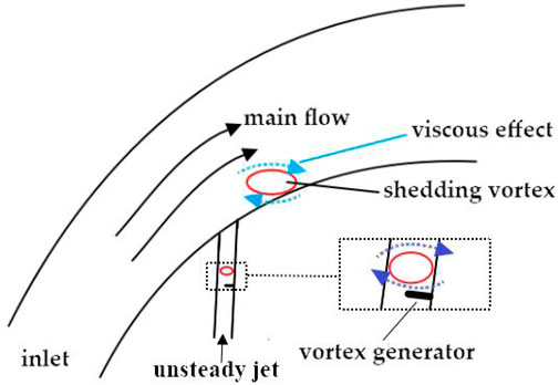
FIGURE 9. Schematic representation of a NCFC method for jet flow control.
To simulate the jet, we set up a bypass flow connected to the main flow passage. Two positions are studied. In the first case, the bypass flow is located at the position of about 25% chord length (marked as PA), which is the generation point of the shedding vortex, so this situation is considered to weaken the shedding vortex. In the second case, the bypass flow is located at the position of about 10% chord length (noted as PB), where the flow starts to separate, so this case is considered to suppress the secondary flow. The incident angle is about 35, and the control frequency is the same as the shedding vortex frequency. Figure 10 shows the two locations and the situation when applying NCFC technology. The bypass flow inlet is set as the velocity inlet, and its expression is as follows:
where
where
where
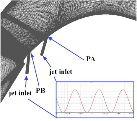
FIGURE 10. Locations of the jet flow control.
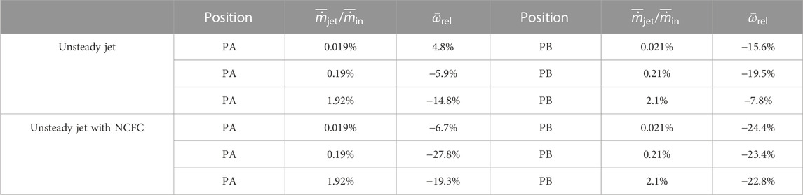
TABLE 1. Performances of the blade-divergent passage under different conditions.
By observing the relative loss coefficient of each scheme at the PA position in Table 1, we can draw the following conclusions: 1) the application of unsteady flow control can reduce the loss coefficient of the blade-divergent passage, and the application of the NCFC method is generally more effective than the application of the conventional method; 2) with the NCFC method, there is an optimum injection to achieve the optimum control effect. When the injection is 0.2% of the main flow, it is almost saturated. At this point, further increasing the injection will cause the efficiency to decrease (indicating that the energy consumed by the flow control will reduce the economy of the flow efficiency improvement); 3) when conventional flow control is used, the control efficiency increases with the increase of the injection in a relatively wide range (the injection is 0.019%–1.9% of the main flow). We can also see that the efficiency of the NCFC method is higher by comparing the characteristic that the NCFC tends to be saturated when the injection is small.
Figures 11, 12 show the flow structures in the blade divergence passage with the NCFC method and with conventional flow control. From the figures, it can be seen that the shedding vortex can be stabilised on the curved blade surface after using the NCFC method, while the development of the shedding vortex after excitation is similar to that of the uncontrolled flow (Figure 4). In addition, the size of the shedding vortex restrained by NCFC is also smaller than that of the conventional method. As a result, the area of the low-velocity zone on the blade surface is smaller than that of the conventional method undergoing NCFC (shown in Figure 13). Figure 14 shows the velocity vector and the interaction of the main flow and the bypass flow. We can see that a vortex is generated in the bypass with the NCFC method and moves downstream. When the vortex moves to the junction of the main flow and the bypass, it can better mix the flows. However, there are no such flow structures for momentum exchange with the conventional method. So we can see from Figure 11 that there is no shedding vortex at the interface between the jet and the main stream, whereas in Figure 12, there is still a shedding vortex at this location.
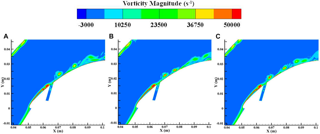
FIGURE 11. Flow structures in the blade-divergent passage with NCFC technology at PA. (A) 1/6T. (B) 3/6T. (C) 5/6T.
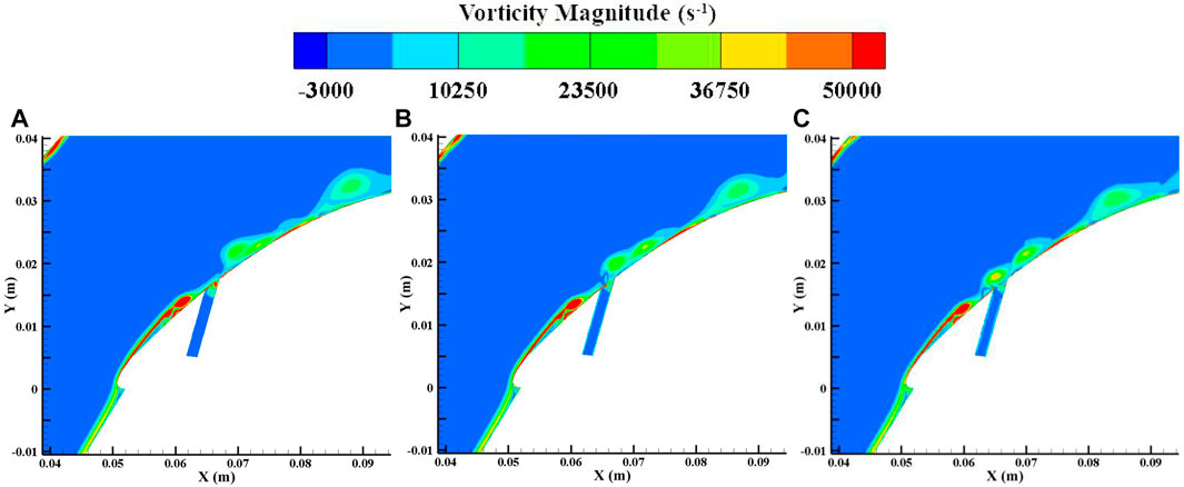
FIGURE 12. Flow structures in the blade-divergent passage with conventional flow control at PA. (A) 1/6T. (B) 3/6T. (C) 5/6T.
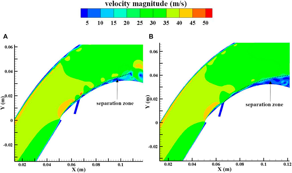
FIGURE 13. Velocity distribution at 3/6T. (A) NCFC method. (B) Conventional flow control.

FIGURE 14. Vectors in the bypass flow. (A) NCFC method. (B) Conventional flow control.
In this study, flow separation occurs at the leading edge of the blade, so we set the flow control position at 10% chord length. Table 1 also shows the performance comparison between conventional flow control and the NCFC method. From the table, we can see that conventional flow control has a positive effect on the suppression of flow separation. Even a small injection mass can improve the performance of the blade-divergent passage. However, as the incident flow increases, its efficiency decreases. The law of jet mass flow and control effect is different from that of PA. For the NCFC method, it performs well under different incident flow rates, and the performance improvement is similar under different incident flow rates. This reflects that the NCFC method is not sensitive to the injection flow mass to inhibit flow separation. Overall, the performance improvement of the NCFC method is slightly better than that of the conventional method.
Figure 15 shows a comparison of instantaneous vorticity with conventional flow control and the NCFC method under large injection masses. Figure 16 shows the instantaneous velocity contribution. It can be seen from the two figures that the NCFC method uses the vortices generated in the bypass to enhance the momentum exchange in the main flow, which is similar to a common vortex generator technology. However, conventional flow control uses a jet to accelerate the low-energy flow at the blade surface. Since the shedding vortex is not generated at position PB, the leading edge separation could be considered a stable flow, so applying unsteady flow control at this position actually takes advantage of the “steady” part of the jet.
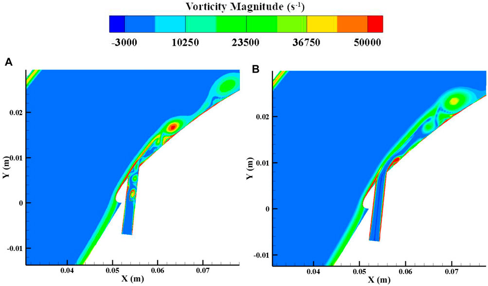
FIGURE 15. Instantaneous vorticity distribution of the large injection flow mass rate. (A) NCFC method. (B) Conventional flow control.
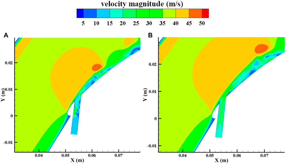
FIGURE 16. Instantaneous velocity distribution of the large injection flow mass rate. (A) NCFC method. (B) Conventional flow control.
From the aforementioned analysis, we have reason to believe that the NCFC method utilises both the unsteady effect and the negative circulation effect, so its performance is superior to the conventional unsteady flow control technology under most working conditions. In addition, we recommend using the NCFC method with a medium injection intensity (about 0.2% of the main flow mass) because, in this case, the NCFC method performs well in both shedding vortex suppression and separation flow control.
In our previous studies, we found that flow control was most effective when positioned near the separation point of the shedding vortex (Lu et al, 2022). Other researchers have investigated the sensitivity of the control position (Amitay et al, 2001) (Shojaefar et al, 2005). So one of the issues we need to look at is the sensitivity of the location of the control point. However, the reality is that as the operating conditions of compressors and such fluid machines change, this can lead to variations in pneumatic parameters such as the angle of attack, so that setting the control point at a single fixed position may be effective in some operating conditions but fail in many others. Moreover, through our research into NCFC technology, we found that this method was less sensitive to the location of the control point. We therefore analysed two locations: PA (similar to our previous studies, set close to the separation point) and PB (quite some distance in front of the shedding vortex separation point). As the data in Table 1 show, the control effect is still positive, although the setting at position PA is less effective than the setting at PB when the energy input is small. When the energy input increases, the control effect does not differ much from the setting at PB. Therefore, our conclusion and recommendation is to set the control point upstream of the predicted shedding vortex separation point to account for changes in operating conditions or to partially resolve the uncertainty in the location of the separation point.
In order to improve and complete the theoretical understanding of the blade suction shedding vortex and to lay the foundation for the adoption of a proper flow control method, a two-dimensional vortex model is introduced in this paper and numerical simulation is carried out for verification. The conclusions are as follows:
(1) An elliptical vortex is used to analyse the behaviour of the shedding vortex in a blade-divergent passage. Three typical external factors are studied individually depending on the model: the main flow extrusion effect, the main flow and solid wall viscous effect, and the transport effect. These factors can also be combined to analyse more complex situations.
(2) The transport effect on the shedding vortex is a necessary condition to influence the shedding vortex. The effect of the extrusion effect will be much greater than that of the viscous effect on the shedding vortex. Therefore, a flow control concept based on negative circulation is proposed to compensate for the viscous effect, which is known as NCFC.
(3) An NCFC device is designed and realised by a vortex generator installed in a tube connected to the blade surface through a hole. Through numerical simulation, it is found that the NCFC method is superior to conventional unsteady flow control for improving the performance of the blade-divergent passage in most cases.
(4) There is an optimum injection to suppress the shedding vortex with NCFC, which is about 0.2% of the main flow mass. However, with conventional unsteady flow control, the control efficiency increases with increasing injection over a wide range, implying that NCFC is more efficient than conventional flow control for the shedding vortex.
(5) The control mechanism of the NCFC and conventional unsteady flow control for the separation flow is similar to that of a steady flow control. The former uses a vortex to increase the exchange between the main flow and the low-energy flow at the blade surface. The latter uses injection to accelerate the low-energy flow close to the blade.
(6) Due to its high efficiency in shedding vortex control and its insensitivity to separation flow control, the NCFC method is highly recommended for adapting to the changing flow field under variable operating conditions in practice.
The original contributions presented in the study are included in the article/Supplementary material; further inquiries can be directed to the corresponding author.
SH carried out the establishment of the model, presentation of strategies, data analysis, and wrote the first draft. WL assisted in the establishment of a model and the improvement of strategies. XX assisted in data analysis and polished the manuscript. LQ helped with the revision of the manuscript. All authors contributed to the article and approved the submitted version.
This research was funded by the Zhejiang Provincial Natural Science Foundation of China, Grant No. LQ20E060004. This research was also supported by the Fundamental Research Funds for the Ningbo University of Technology.
The authors are also grateful to Huang Guoping (NUAA) for technical aspects.
The authors declare that the research was conducted in the absence of any commercial or financial relationships that could be construed as a potential conflict of interest.
All claims expressed in this article are solely those of the authors and do not necessarily represent those of their affiliated organizations, or those of the publisher, the editors, and the reviewers. Any product that may be evaluated in this article, or claim that may be made by its manufacturer, is not guaranteed or endorsed by the publisher.
Abdolrahim, R., Hamid, M., and Bert, B. (2019). Active flow control for power enhancement of vertical axis wind turbines: Leading-edge slot suction. Energy 189, 116131. doi:10.1016/j.energy.2019.116131
Akhtar, I., Marzouk, O., and Nayfeh, A. (2009). A van der Pol-Duffing oscillator model of hydrodynamic forces on canonical structures. J. Comput. Nonlinear Dyn. 4 (4), 041006. doi:10.1115/1.3192127
Amitay, M., Smith, D., Kibens, V., Parekh, D., and Glezer, A. (2001). Aerodynamic flow control over an unconventional airfoil using synthetic jet actuators. AIAA J. 39 (3), 361–370. doi:10.2514/2.1323
Braunscheidel, E., Culley, D., and Zaman, K. (2008). “Application of synthetic jets to reduce stator flow separation in a low speed axial compressor,” in In 46th AIAA aerospace sciences meeting and exhibit, Nevada, United States, January, 2008, 7–10.
Balduzzi, F., Bianchini, A., Ferrara, G., and Ferrari, L. (2016a). Dimensionless numbers for the assessment of mesh and timestep requirements in CFD simulations of Darrieus wind turbines. Energy 97, 246–261. doi:10.1016/j.energy.2015.12.111
Balduzzi, F., Bianchini, A., Maleci, Riccardo., Ferrara, Giovanni., and Ferrari, L. (2016b). Critical issues in the CFD simulation of Darrieus wind turbines. Renew. Energy 85, 419–435. doi:10.1016/j.renene.2015.06.048
Chen, J., Lu, W., Huang, G., Zhu, J., and Wang, J. (2017). Research on pulsed jet flow control without external energy in a blade cascade. Energies 10 (12), 2004. doi:10.3390/en10122004
Chen, S., Tu, T., Zeng, C., and Meng, Q. (2022). Modal analysis of compressor cascades with sweeping jet actuator and pulsed jet for active flow control based on large Eddy simulation. Aerosp. Sci. Technol. 131, 107997. doi:10.1016/j.ast.2022.107997
Choi, M., Baek, J. H., Oh, S. H., and Ki, D. J. (2008). Role of hub-corner-separation on rotating stall in an axial compressor. Trans. Jpn. Soc. Aeronautical Space Sci. 51 (172), 93–100. doi:10.2322/tjsass.51.93
Feng, Q., Hou, A., Liu, R., Zhou, B., and Zhang, M. (2022). Separation flow and blade dynamic response characteristic of compressor at high attack angle. J. Beijing Univ. Aeronautics Astronautics 43 (7), 1410–1418. doi:10.13700/j.bh.1001-5965.2016.0912
Ferziger, J., and Peric, M. (2002). Computational methods for fluid dynamics. 3. Berlin, Germany: Springer.
Gbadebo, S. A., Cumpsty, N. A., and Hynes, T. P. (2008). Control of three-dimensional separations in axial compressors by tailored boundary layer suction. J. Turbomach. 130 (1), 011004. doi:10.1115/1.2749294
Gbadebo, S. A., Cumpsty, N. A., and Hynes, T. P. (2005). Three-dimensional separations in axial compressors. J. Turbomach. 127 (2), 331–339. doi:10.1115/1.1811093
Giorgi, M., Luca, C., Ficarella, A., and Marra, F. (2015). Comparison between synthetic jets and continuous jets for active flow control: Application on a NACA 0015 and a compressor stator cascade. Aerosp. Sci. Technol. 43, 256–280. doi:10.1016/j.ast.2015.03.004
Hong, S., Chi, J., Xiang, X., and Lu, W. (2022). Theoretical model and numerical analysis of the tip leakage vortex variations of a centrifugal compressor. Aerospace 9 (12), 830. doi:10.3390/aerospace9120830
Hong, S., and Huang, G. (2017). Introducing DMD method to study dynamic structures of flow separation with and without control. Acta Aeronautica Astronautica Sinica 38 (8), 120876. doi:10.7527/S1000-6893.2016.120876
Huang, G., Lu, W., Zhu, J., Fu, X., and Wang, J. (2017). A nonlinear dynamic model for unsteady separated flow control and its mechanism analysis. J. Fluid Mech. 826, 942–974. doi:10.1017/jfm.2017.321
Ku, W., Girvan, M., and Ott, E. (2015). Dynamical transitions in large systems of mean field-coupled Landau-Stuart oscillators: Extensive chaos and cluster states. Chaos 25 (12), 123122. doi:10.1063/1.4938534
Lei, V. M. (2006). A simple criterion for three-dimensional flow separation in axial compressors. Ph. D. thesis. Cambridge, United States: Massachusetts Institute of Technology.
Liesner, K., Meyer, R., Lemke, M., Gmelin, C., and Thiele, F. (2010). “On the efficiency of secondary flow suction in a compressor cascade,” in In Proceedings of the ASME Turbo Expo 2010: Power for Land, Sea, and Air, Glasgow, United Kingdom, 14–18 June 2010.
Likiewicz, G., Kabalyk, K., Jaeschke, A., Grapow, F., Kulak, M., Stajuda, M., et al. (2020). Unstable flow structures present at different rotational velocities of the centrifugal compressor. Energies 13 (16), 4146. doi:10.3390/en13164146
Lu, W., Huang, G., and Wang, J. (2022). Analysis of pulsed suction flow control behavior based on a nonlinear reduced-order model. Aerosp. Sci. Technol. 122, 107410. doi:10.1016/j.ast.2022.107410
Ma, D., Li, G., Yang, M., and Wang, S. (2018). Research of the suction flow control on wings at low Reynolds numbers. Proc. Institution Mech. Eng. Part G J. Aerosp. Eng. 232 (8), 1515–1528. doi:10.1177/0954410017694057
Marzouk, O., Nayfeh, A., Akhtar, I., and Arafat, H. (2007). Modeling steady-state and transient forces on a cylinder. J. Vib. Control 13 (7), 1065–1091. doi:10.1177/1077546307078737
Matejka, M., Popelka, L., Safarik, P., and Nozicka, J. (2008). “Influence of active methods of flow control on compressor blade cascade flow,” in In Proceedings of the ASME Turbo Expo 2008: Power for Land, Sea, and Air, Berlin, Germany, June, 2008, 9–13.
Orszag, S. (1971). Accurate solution of the Orr–Sommerfeld stability equation. J. Fluid Mech. 50 (4), 689–703. doi:10.1017/S0022112071002842
Shojaefar, M., Noorpoor, A., Avanesians, A., and Ghaffarpou, M. (2005). Numerical investigation of flow control by suction and injection on a subsonic airfoil. Am. J. Appl. Sci. 2 (10), 1474–1480. doi:10.3844/ajassp.2005.1474.1480
Skop, R. A. (1995). “A nonlinear oscillator model for vortex shedding from a forced cylinder. Part 2: Shear flow and axial diffusion,” in Paper presented at the The Fifth International Offshore and Polar Engineering Conference, The Hague, The Netherlands, June, 1995, 11.
Stuart, J. (1967). On finite amplitude oscillations in laminar mixing layers. J. Fluid Mech. 29 (3), 417–440. doi:10.1017/S0022112067000941
Stuart, J. (1958). On the non-linear mechanics of hydrodynamic stability. J. Fluid Mech. 4 (1), 1–21. doi:10.1017/S0022112058000276
Tang, Y., Liu, Y., and Sciubba, E. (2020). Aerodynamic investigation of datum and slotted blade profiles under different mach number conditions. Energies 13 (7), 1673. doi:10.3390/en13071673
Theofilis, V. (2003). Advances in global linear instability analysis of nonparallel and three-dimensional flows. Prog. Aerosp. Sci. 39 (4), 249–315. doi:10.1016/S0376-0421(02)00030-1
Thompson, M., and Gal, P. (2004). The Stuart-Landau model applied to wake transition revisited. Eur. J. Mech. B-fluids 23 (1), 219–228. doi:10.1016/j.euromechflu.2003.09.012
Yang, Z., Mao, X., and Liu, B. (2021). Numerical investigation of secondary flow control by boundary layer suction on the end-wall in a highly-loaded axial compressor cascade. J. Aeronautics, Astronautics Aviat. 53 (4), 483–496.
Yousefi, K., and Saleh, R. (2015). Three-dimensional suction flow control and suction jet length optimization of NACA 0012 wing. Meccanica 50 (6), 1481–1494. doi:10.1007/s11012-015-0100-9
Keywords: unsteady flow control, vortex model, shedding vortex, flow control mechanism, compressor blade, negative circulation
Citation: Hong S, Lu W, Xiang X and Qiu L (2023) An unsteady flow control technique based on negative circulation conception and its application to a blade-divergent passage. Front. Energy Res. 11:1184687. doi: 10.3389/fenrg.2023.1184687
Received: 12 March 2023; Accepted: 01 June 2023;
Published: 30 June 2023.
Edited by:
Alexandre Presas, Universitat Politecnica de Catalunya, SpainReviewed by:
Jingwei Cao, Tsinghua University, ChinaCopyright © 2023 Hong, Lu, Xiang and Qiu. This is an open-access article distributed under the terms of the Creative Commons Attribution License (CC BY). The use, distribution or reproduction in other forums is permitted, provided the original author(s) and the copyright owner(s) are credited and that the original publication in this journal is cited, in accordance with accepted academic practice. No use, distribution or reproduction is permitted which does not comply with these terms.
*Correspondence: Shuli Hong, aG9uZ18wODE1QDE2My5jb20=
Disclaimer: All claims expressed in this article are solely those of the authors and do not necessarily represent those of their affiliated organizations, or those of the publisher, the editors and the reviewers. Any product that may be evaluated in this article or claim that may be made by its manufacturer is not guaranteed or endorsed by the publisher.
Research integrity at Frontiers
Learn more about the work of our research integrity team to safeguard the quality of each article we publish.