 Yingwei Wang
 Yufeng Guo1*
94% of researchers rate our articles as excellent or good
Learn more about the work of our research integrity team to safeguard the quality of each article we publish.
Find out more
ORIGINAL RESEARCH article
Front. Energy Res., 30 May 2023
Sec. Process and Energy Systems Engineering
Volume 11 - 2023 | https://doi.org/10.3389/fenrg.2023.1181996
This article is part of the Research TopicKey Technologies for Hybrid Energy System Planning and OperationView all 10 articles
The operational range of a wind turbine is typically divided into two regions based on wind speed: below and above the rated wind speed. The turbine switches between these two regions depending on the prevailing wind speed; however, during the transition, the generator may undergo transient shocks in torque, which can negatively impact both the mechanical load of the turbine and the reliability of the power system. This article presents a flexible torque control method for wind turbines, specifically designed to handle the transition between wind speed regions when the turbine is participating in frequency regulation. First, the anomalies in generator torque caused by traditional torque control methods during frequency response scenarios are analyzed. Next, two methods—dynamic deloading and flexible torque control—are developed to address these issues. The developed methods set transition regions based on generator speed, which helps to reduce the impact of transient changes in generator torque. Importantly, the addition of transition regions does not require additional feedback, making the controller easy to implement. The response characteristics of the proposed methods are then analyzed under different deloading factors and wind speeds using model linearization. Simulation studies are presented to verify the effectiveness of the proposed methods. Overall, this study demonstrates the potential value of flexible torque control methods for wind turbines, which can help to mitigate the negative impact of torque shocks and improve the reliability and efficiency of wind power systems.
With the increasing integration of wind energy, the frequency stability of power systems has been falling (Wang et al., 2023; Xue et al., 2022). However, the participation of wind turbines in frequency response through overspeed control can significantly improve frequency stability (Xiong et al., 2022a; Yang et al., 2022). Due to the randomness of wind speed and system frequency, and the increase in complexity of the control system with the introduction of the frequency control loop, the control system plays a significant role in wind energy conversion systems (Boyle et al., 2021; Xiong et al., 2023). In terms of wind turbine control without consideration of frequency response, the control system includes constant power control above the rated wind speed, power tracking control below the rated wind speed, and regional switching control under the prevailing wind speed (Suna et al., 2020; Xiong et al., 2022b). However, the introduction of a frequency response control loop makes the traditional switching control inapplicable, which causes abnormal fluctuations of generator torque and increases mechanical load. In addition, this causes abnormal output power fluctuations and damages the frequency stability of the system (Wang et al., 2020). Therefore, flexible torque control of wind turbines requires investigation, considering frequency response under wind speeds that cross the regions of operation.
Whether the wind speed is above or below the rated wind speed, the wind turbine control and corresponding frequency response methods proposed by scholars can allow for stable operation of the wind turbine. When the wind speed is lower than the rated wind speed, a control approach has been proposed to provide an emulated inertial response when the wind turbine is operating at the maximum power point. The proposed method mitigates the antagonistic interaction between maximum power point tracking (MPPT) control and inertia control (Bastiani and Vasques de Oliveira, 2021). An inertial power-based perturb and observe method has been proposed for MPPT control of wind turbines. The dynamical performance is increased by accurately identifying the maximum power point with high performance, either in the transient or in the steady state (Karabacak, 2019). A robust finite-time controller based on the Lyapunov function has been proposed to improve the transient performance of wind turbine speed-tracking and the robustness of the controlled system (Shotorbania et al., 2019). Finally, sliding mode control has been proposed to control MPPT, with aerodynamic torque being observed to mitigate the vibrations of the wind turbine (Pan and Shao, 2020).
When the wind speed is above the rated wind speed, a gain scheduled pitch controller has been designed by solving linear matrix inequalities and is used for stability control of the wind turbine (Bundi et al., 2020). An application of neural network-based model predictive control is presented to offer a stable response to frequency changes and significantly enhance the capability of reference tracking of the wind turbine (Kayedpour et al., 2022). In addition, the two-degree-of-freedom robust individual pitch controller is proposed to reduce loads in the above-rated region (Tang et al., 2022).
When the wind speed is around the rated wind speed (prevailing wind speed), the current model of switching control does not consider the frequency response of the system. The stability criteria for the switching operation of wind turbines are analyzed using second-order linear systems under the non-linear control framework (Palejiya et al., 2015). A bumpless transfer scheme has been presented to reduce the associated power fluctuation and fatigue loading (Chen et al., 2016). A method has been proposed to protect the wind turbine against the impulses and intense oscillations involved in switching between the different regions (Ali and Moradi, 2020). A method for adaptive envelope protection control of wind turbines under varying operational conditions has been proposed by Sahin and Yavrucuk (2022). A linear parameter-varying anti-windup controller has also been proposed to improve the transition between low- and high-wind speed operations (Inthamoussou et al., 2014). Additionally, it has been proposed that the dynamic switching transient be driven by predefined wind speed crossing events in order to mitigate step generator torque fluctuation (Xing et al., 2019). It can be noted that these recently proposed switching control methods focus only on a model of wind turbine control that does not participate in and is not applicable to frequency response.
To enable the application of switching control to frequency response, this article proposes a flexible torque control method for wind speed crossing regions. First, the phenomenon in which the traditional method for frequency regulation causes transient shocks to generator torque in the wind speed crossing region is analyzed. Next, the region around the prevailing wind speed is divided into transition regions of operation. Dynamic deloading and flexible torque control methods are proposed to allow flexible generator torque transfer at wind speeds around the prevailing wind speed. Finally, the dynamic characteristics of the proposed method are analyzed through linearization of the model and the effectiveness of the proposed method is verified by simulation.
The main contribution of this article is the proposal of a control scheme that provides flexible switching control under the wind crossing region, which is suitable for frequency regulation. Unlike conventional switching control methods, under this approach, generator torque is unaffected by the wind speed crossing region and frequency response. Wind turbines can provide stable generator and power output, which mitigates wind turbine vibration and improves frequency stability.
The remainder of this paper is organized into five sections. Section 2 provides an overview of conventional frequency regulation methods and discusses the abnormal torque fluctuation caused by the conventional method. Section 3 presents the proposed dynamic deloading and flexible torque control scheme, which overcomes the problems associated with conventional frequency control when applied under the wind speed crossing region. The results of the case studies are presented and analyzed in Section 4. Finally, Section 5 presents the conclusions drawn from the findings and identifies avenues for future research.
In this section, the dynamic model of wind turbines is first described, the traditional torque and pitch control methods are introduced, and the frequency response method based on traditional torque control is also introduced. Finally, the problem is introduced, namely, that the frequency response of wind turbines under the conventional control method causes transient shocks to generator torque.
The mechanical energy captured by the wind turbine is evaluated by Eq. 1. The rotor and generator are defined as in Eqs 2, 3.
where Pmec is the mechanical power (W), ρ is the air density (kg/m3), v is the wind speed (m/s), R is the length of the blade (m), ωr is the rotor speed (rad/s), ωg is the generator speed (rad/s), Cp is the power coefficient, θ is the pitch angle (deg), Ta is the rotor torque (Nm), Tg is the generator torque (Nm), and ηg is the gearbox ratio.
To ensure that the wind turbine runs stably and to maximize the power output, many control methods have been proposed. Torque control (short for generator torque control of the wind turbine) can be divided into two regions according to wind speed, as shown in Figure 1. This torque control method is well-used and has been reported on by many scholars (Grunnet et al., 2010; Zhao et al., 2015; Zhao et al., 2017; Zhang et al., 2018; Wang et al., 2021; Wang et al., 2022). Region 1 is defined as the region where wind speed is below the rated wind speed, referred to as the partial-load region. In this region, the most commonly used control method in engineering is the look-up table method, employed to ensure that the wind turbine runs stably while processing MPPT. For simplification for the purpose of this study, the look-up table method can be simplified to Eq. 4. Region 2 is that the region where wind speed is above the rated wind speed, referred to as the full-load region. In this region, the main objective of torque control is maintaining a constant output power. The control method is expressed in Eq. 5. Furthermore, to limit the capture of wind energy in region 2, pitch control is activated, as determined by Eq. 6.
where kopt is the generator control factor; Prated is the rated power (W); Trated is the rated generator torque (Nm); θref is the reference pitch angle (deg); kp and ki are the proportional and integral gains of the PI controller, respectively; ωgN is the rated generator speed (rad/s); and ka1 and ka2 are gain coefficients related to the pitch angle.
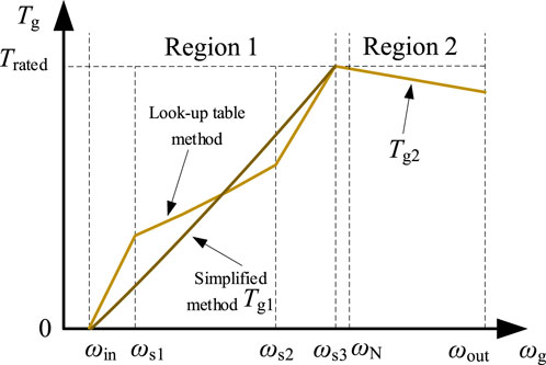
FIGURE 1. Generator torque control under different regions [ωs1, ωs2, and ωs3 are the set generator speed (rad/s)].
It is worth noting that transition between the torque control regions is mainly judged based on the generator speed, but is also related to the captured power and pitch angle. The switching generator speed is set to speed ωs3 instead of the rated speed, as shown in Figure 1, which can enable advanced integration of the pitch angle to maximize the operational stability of the wind turbine. It can be seen that torque control is divided into two regions: Eqs 4, 5. In the conversion between regions, judgment of the generator speed is significant, and the set speed ωs3 is usually slightly lower than the rated speed. Figure 2 depicts the speed and torque of the generator during the transition between various operating regions of the wind turbine if the set speed ωs3 is the rated rotational speed, and in the absence of frequency response. It can be seen that when the generator speed crosses the set point, the generator torque crosses between different operating regions. Since the problem of transition in generator torque crossing is considered in the design of the traditional control method, the actual output generator torque shown in Figure 2 is smooth.
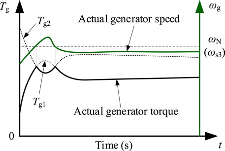
FIGURE 2. Generator speed and torque during the transitions between various operating regions.
Adjustment of wind turbine speed can change the power captured. Figure 3 shows the mechanical power captured at different rotor speeds at a zero pitch angle. It can be seen that the wind turbine attains maximum power (Popt) only when the rotor reaches a specific speed (ωopt). In order to retain the capacity for frequency response, the wind turbine does not operate at the optimal power point A but rather at a suboptimal power point B or C through deloading control. In addition, reducing the generator speed under the same output power would increase the generator torque, which is not conducive to reducing the fatigue load. Thus, point B is the optimal choice for deloading control, that is, overspeed control.
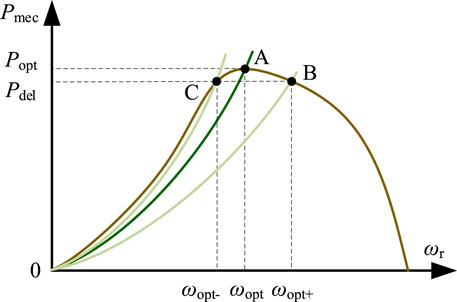
FIGURE 3. Mechanical power at different rotor speeds at zero-pitch angles.
The frequency response method, which utilizes overspeed control, is presented in block diagram form in Figure 4. Frequency response methods based on different methods of torque control are shown in Eqs 7, 8.
where γ is the deloading factor, kFR is the frequency response gain (p.u.), kOPT is the torque control gain (p.u.), and Δf is the frequency deviation of the power system (p.u.).
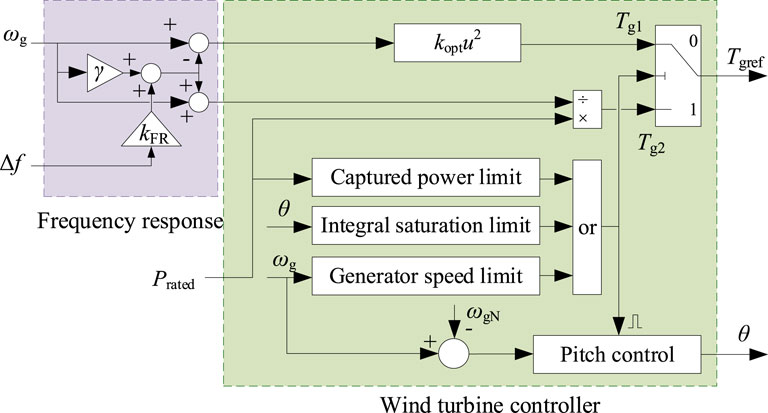
FIGURE 4. Block diagram ffor the frequency response method based on overspeed control.
Generator torque under ideal deloading control can be simplified as shown in Figure 5A. Overspeed control (deloading torque) can reduce generator torque at the same speed. However, since the deloading factor is fixed under conventional control methods, generator torque undergoes shocks under region switching, as shown in Figure 5B. Moreover, generator torque cannot be transitioned smoothly between regions 1 and 2, which causes significant transient shocks and a significant increase in mechanical load.
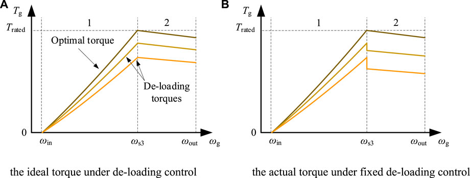
FIGURE 5. Generator torque under deloading control. (A) Ideal torque under deloading control. (B) Actual torque under fixed deloading control.
Generator torque can be smoothed by regulating the deloading factor, which can be represented by the process from the dotted line to the solid line in Figure 6A. However, the generator torque participating in the frequency response is related not only to the generator speed but also to system frequency deviation. Figure 6A shows the generator torque when the wind turbine participates in frequency response by employing deloading control. If system frequency deviation were introduced into the torque control loop, generator torque would fall within the solid line of deloading torque and the yellow area. Since the system frequency is random to the wind turbine, the feedback of frequency deviation causes generator torque to vary irregularly within a specific range (the yellow-shaded parts of the two regions). There exist alternative techniques for regulating the frequency of a wind turbine, such as controlling the rotor speed to release kinetic energy, without requiring deloading. If a wind turbine is not subjected to de-rating control, its deloading factor can be deemed to be zero. Even in the absence of de-rating control, transient oscillations in generator torque may occur in the yellow region illustrated in Figure 6B, owing to frequency response dynamics.
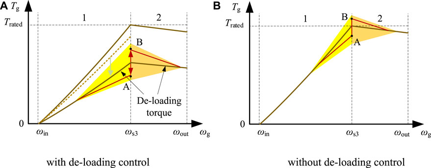
FIGURE 6. Generator torque when the wind turbine participates in frequency response by employing deloading control: (A) with deloading control; (B) without deloading control.
The frequency response can cause frequent switching of generator torque between points A and B, resulting in unavoidable transient shocks to the generator torque fluctuations in the crossing region, as depicted in Figure 7. Due to the shift in the optimal operating point caused by overspeed control and frequency response, the generator torque values in regions 1 and 2 under the set speed are unequal, leading to abnormal fluctuations of generator torque in the crossing region. Connections between the generator, gearbox, and spindle can increase the drive train load due to transient fluctuation of the generator torque. The drive train dynamic equation is shown in Eqs 9–11.
where Ts is the shaft torque (Nm), Jg is the generator mass (kg·m2), Jr is the rotor mass (kg·m2), K is the shaft spring constant (Nm/rad), B is the shaft viscous friction (Nm·s/rad), and Ta is the rotor torque (Nm).
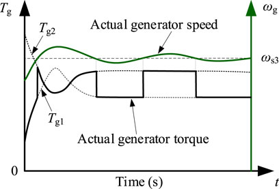
FIGURE 7. Transient shocks to generator torque fluctuations.
In summary, the current frequency response method has two main problems: transient shocks to generator torque caused by a fixed deloading factor, and transient shocks to generator torque caused by frequency regulation.
Dynamic deloading and flexible generator torque control methods are proposed here to address the challenges described in the previous section. The response characteristics of the control scheme are also analyzed.
Under a fixed deloading factor, generator torque cannot smoothly cross the set speed, resulting in step fluctuation in generator torque. However, when the deloading factor is not fixed, generator torque at the set speed can be equalized by adjusting the deloading factor. In other words, when frequency deviation is not considered, Eqs 7, 8 can be equalized to obtain the deloading factor of region 1. The deloading factor for region 1 is calculated by Eq. 12.
where γ1 and γ2 are the deloading factors of regions 1 and 2, respectively. The determination of γ2 is typically left to the discretion of the user. When setting the value of γ2, careful consideration is given to achieving a balance between the available spare capacity and the capacity for frequency adjustment in the wind turbine. In practice, it is common for γ2 to be set at either 5% or 10%.
The introduction of frequency deviation to torque control systems has led to transient shocks to generator torque. Therefore, it is necessary to set the generator torque transition region so that the torque undergoes a smooth transition between different regions. The torque transition region is referred to as the
The process of torque crossing between regions 1 and 2 can be divided into two scenarios: region 1 to region 2, and region 2 to region 1. Figure 8 shows the generator torque crossing process from different points. When the torque shifts from point A to point B, two scenarios exist for torque increase and decrease (
where
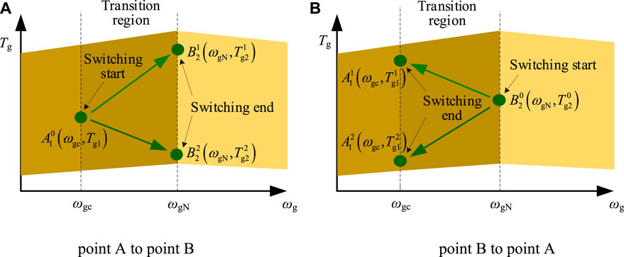
FIGURE 8. Generator torque crossing between different points: (A) point A to point B; (B) point B to point A.
The control block diagram is shown in Figure 9. Generator speed governs the torque control, as follows:
• If the generator speed is less than the transition speed, the torque control system adopts the control method shown in Eq. 7.
• If the speed is within the crossing area (between the transition speed and the rated speed), the torque control system adopts the control method shown in Eq. 13.
• If the speed exceeds the rated speed, the torque control system adopts the control method shown in Eq. 8.
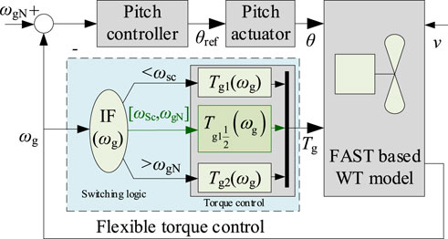
FIGURE 9. Control block diagram based on flexible torque control.
Note that the proposed flexible torque method only needs to detect the generator speed, which makes the method relatively easy to apply in engineering practice.
A closed-loop control block diagram, as presented in Figure 10, was constructed to examine the response characteristics of the proposed method under different wind speeds and deloading factors For this purpose, error transfer functions were derived to analyze the response characteristics. The error transfer function for torque fluctuation and frequency fluctuation can be seen in Eq. 14; the error transfer function for torque fluctuation and wind speed fluctuation can be seen in Eq. 15.
where
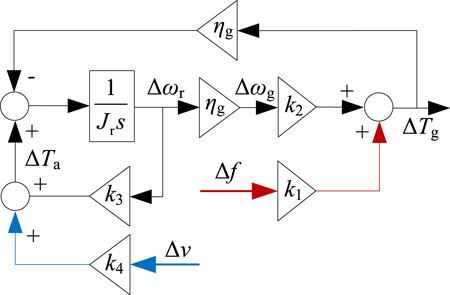
FIGURE 10. Closed-loop control block diagram.
The Bode diagram for Eq. 14 is shown in Figure 11A, in which the fluctuation of generator torque in the transition region is affected by wind speed. The impact mechanism is as follows: as the wind speed increases, torque fluctuations increase, and as the deloading factor increases, torque fluctuations increase. The Bode diagram for Eq. 15 is shown in Figure 11B, in which it can be seen that torque fluctuations increase with increased wind speed, while torque fluctuations decrease with an increase in deloading factor.
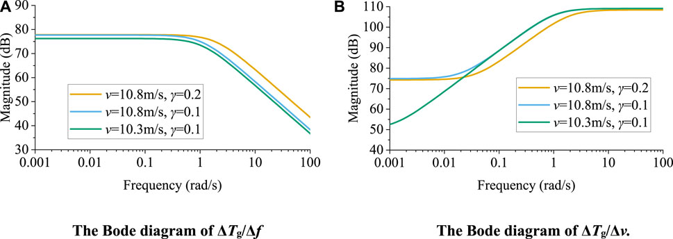
FIGURE 11. Bode diagrams for (A) ΔTg/Δf and (B) ΔTg/Δv.
Different operating conditions were used as case studies to further illustrate the shortcomings of current control methods and to verify the effectiveness of the proposed method. Wind speed was generated using TurbSim (Kelley and Jonkman, 2006). The damage equivalent load was used to evaluate the fatigue loading of the wind turbine, which was calculated using the MCrunch package (Buhl, 2008).
The proposed flexible torque control system was first validated under turbulent wind speed conditions. In this scenario, the wind turbine only performs deloading control and does not participate in the frequency response. The average wind speed, as shown, was 10.68 m/s. The deloading factor γ2 was 0.13. Figure 12 shows the generator speed, torque, and power output under different methods. FTC represents the proposed flexible torque control method and CON the conventional torque control method. Figure 12A shows the generator speed for each of the different methods; it can be seen that generator speed under the proposed FTC method is almost the same as that under the traditional method. Furthermore, under overspeed control, the generator speed of the wind turbine increases relative to that under MPPT. Based on the generator torque patterns shown in Figure 12B, it can be seen that generator speed under the traditional method fluctuates abnormally at certain moments, for the reason given in the above analysis. The proposed FTC method can avoid transient shocks, which greatly reduces the mechanical load of the wind turbine. Compared to generator torque under MPPT, generator torque under derating control is reduced.
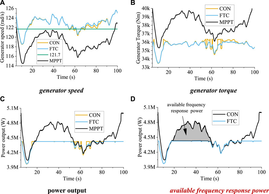
FIGURE 12. Operational states of the wind turbine under the different methods. In this scenario, the wind turbine only performs deloading control and does not participate in the frequency response. (A) Generator speed; (B) generator torque; (C) power output; (D) available frequency response power.
The output power of the different methods is shown in Figure 12C. It can be seen that power output fluctuates abnormally under the traditional method (CON), which is not conducive to the frequency stability of the power system. The proposed method can produce smoother power output, which is beneficial to the stability of the power system. Furthermore, due to the implementation of deloading control, a portion of power (between 20 and 50 s) is reserved. Thus, the shaded region in Figure 12D displays the frequency response power that can be achieved. Wind turbines with sufficient power reserve can contribute to the frequency response of the system from 20 to 50 s. In the period from 50 to 80 s, wind turbines typically respond to frequency through the kinetic energy of the rotor due to insufficient wind speed.
In summary, the proposed method can provide the wind turbine with stable mechanical dynamics and power output under deloading control.
In this scenario, the wind turbine engages in frequency response through dynamic deloading control. Generator speeds under the different methods are shown in Figure 13A. Similarly to the scenario with no participation in the frequency response, the differences in generator speed under the different methods are insignificant. Generator torque under the different methods is shown in Figure 13B. It can be seen that generator torque under the traditional method fluctuates abnormally at 35 s. Generator torque under the proposed method is smooth, which is beneficial for the mitigation of fatigue load and the stability of the power system. The output power of the different methods is shown in Figure 13C. It can be seen that output power fluctuates abnormally under the traditional method. If the frequency response is enacted according to the traditional method, system frequency may be negatively affected by the shock to power output in the transition region. The proposed method can smooth the output power and increase the power participating in the frequency response, which can significantly improve frequency stability and the profitability of the wind farm. The system frequency deviation under each of the different methods is shown in Figure 13D. It can be seen that frequency deviation under the conventional method shifts suddenly at 35 s due to transient shocks to generator torque. Under the proposed FTC scheme, saltation of frequency deviation caused by transient shocks can be avoided.
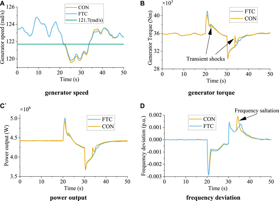
FIGURE 13. Operational states of the wind turbine under different methods under frequency regulation. (A) Generator speed; (B) generator torque; (C) power output; (D) frequency deviation.
In this study, the long-term dynamics of the power system and mechanical load of wind turbines were analyzed to explain how the proposed FTC can reduce mechanical load and improve power system stability. The simulation used an average wind speed of 11.4 m/s, turbulence strength of 0.1, and random fluctuations in system load every 20 s, with an amplitude not exceeding 4% over a period of 600 s.
Figure 14A illustrates generator torque under various methods under random load conditions. The traditional approach results in frequent torque transients due to wind speed changes near the rated wind speed, leading to significant torque fluctuations, as evident in the local amplification diagram (360–400 s and 510–550 s). In contrast, the proposed FTC method effectively curbs abnormal torque fluctuations.
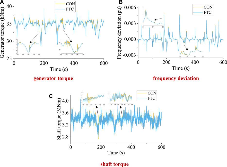
FIGURE 14. System frequency and wind turbine mechanical load for different methods under random load. (A) Generator torque; (B) frequency deviation; (C) shaft torque.
Figure 14B presents system frequency under different methods under random loads. The proposed FTC method successfully prevents abnormal frequency fluctuations caused by torque fluctuations and reduces the maximum frequency deviation to some extent, as evident in the locally enlarged images (180–200 s and 320–350 s). The drive train, which is directly connected to the generator, is the component most affected by transient fluctuations in generator torque.
As depicted in Figure 14C, abnormal generator torque fluctuations result in shaft torque abnormalities and increase twisting in the drive train, leading to gearbox damage. The local amplification diagrams (180–190 s and 316–328 s) clearly indicate these abnormalities, which aggravate fatigue load of the drive train and reduce the service life of the wind turbine. Table 1 displays the damage equivalent load (DEL) of the drive train torque under random load conditions for the different methods. DEL was 4% lower under the proposed FTC than under traditional methods. In summary, the proposed FTC method is advantageous in reducing mechanical load and improving power system stability, thereby enhancing the performance and durability of the wind turbine.

TABLE 1. Comparison of fatigue load under the different methods under random system load.
To illustrate the generality of the proposed FTC, we compared the generator torque under different frequency response methods. A rotor speed control method used in previous work was adoptedly, and primary frequency regulation, based on droop and inertia control, in turn based on power scheduling, was then tested (Wu et al., 2018). The initial fluctuation time of system load was 2 s. Figure 15 shows the generator torque with and without FTC under droop control and inertia control. As shown from 3 to 8 s, it is clear that the proposed FTC can significantly reduce the fluctuation of generator torque. The above-described results show that the proposed method can be applied to different frequency response methods to reduce abnormal crossing of generator torque.
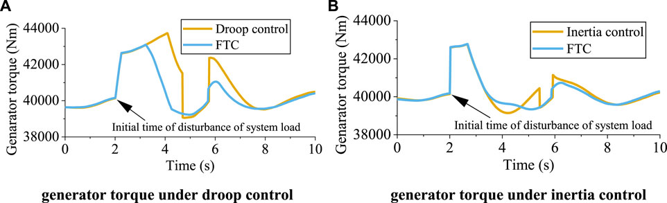
FIGURE 15. Generator torque of the wind turbine under frequency response with and without FTC. (A) Generator torque under droop control; (B) generator torque under inertia control.
This paper has proposed a dynamic derating and flexible torque control method for frequency response in wind turbines within the wind speed crossing region. First, the abnormal torque ride-through phenomenon caused by fixed derating and traditional torque control methods under derating control were analyzed. Next, dynamic deloading and flexible torque control methods were proposed. The effectiveness of the proposed method was verified for turbulent wind with an average velocity near the rated wind speed. The results showed that the proposed method enables the system to avoid abnormal torque fluctuation and allows the wind turbine to operate with greater stability.
The original contributions presented in the study are included in the article/Supplementary Material. Further inquiries can be directed to the corresponding author.
This article was completed collaboratively by the authors. YW, YG, and YD carried out the theoretical research, analyzed the data and the results, wrote the manuscript, and contributed constructive suggestions. WX revised the article. All authors contributed to the article and approved the submitted version.
This work was supported by Science and Technology projects managed by the headquarters of State Grid Corporation of China (grant 5108-202299259A-1-0-ZB). The study was funded by State Grid Corporation of China. The funder was not involved in the study design, data collection, analysis, interpretation, or in the writing of the article or the decision to submit it for publication.
Author WX was employed by the company Liaoning Electric Power Co., Ltd.
The remaining authors declare that the research was conducted in the absence of any commercial or financial relationships that could be construed as a potential conflict of interest.
All claims expressed in this article are solely those of the authors and do not necessarily represent those of their affiliated organizations, or those of the publisher, the editors, and the reviewers. Any product that may be evaluated in this article, or claim that may be made by its manufacturer, is not guaranteed or endorsed by the publisher.
Ali, N., and Moradi, H. (2020). Smooth switching in power control of wind turbines using a combination strategy of hysteresis and modified middle regions. Sustain. Energy Technol. Assessments 37, 100585. doi:10.1016/j.seta.2019.100585
Bastiani, B. A., and Vasques de Oliveira, R. (2021). Adaptive MPPT control applied to virtual synchronous generator to extend the inertial response of type-4 wind turbine generators. Sustain. Energy, Grids Netw. 27, 100504. doi:10.1016/j.segan.2021.100504
Boyle, J., Littler, T., Muyeen, S. M., and Foley, A. M. (2021). An alternative frequency-droop scheme for wind turbines that provide primary frequency regulation via rotor speed control. Int. J. Electr. Power Energy Syst. 133, 107219. doi:10.1016/j.ijepes.2021.107219
Buhl, M. L. (2008) NREL/TP-500-45843139. Denver, CO, USA: Nat. Renew. Energy Lab. Mcrunch user’s guide for version 1.00
Bundi, J. M., Ban, X., Wekesa, D. W., and Ding, S. (2020). Pitch control of small H-type Darrieus vertical axis wind turbines using advanced gain scheduling techniques. Renew. Energy 161, 756–765. doi:10.1016/j.renene.2020.05.184
Chen, Q., Li, Y., and John, E. (2016). Bumpless transfer-based inter-region controller switching of wind turbines for reducing power and load fluctuation. IEEE Trans. Sustain. Energy 7 (1), 23–31. doi:10.1109/tste.2015.2471104
Grunnet, J. D., Soltani, M., Knudsen, T., Kragelund, M. N., and Bak, T. (2010). “Aeolus toolbox for dynamics wind farm model simulation and control,” in Proceedings of the European Wind Energy Conference and Exhibition, Brussels, Belgium, March, 2010, 3119–3129.
Inthamoussou, F. A., Bianchi, F. D., De Battista, H.´an, and Mantz, R. J. (2014). LPV wind turbine control with anti-windup features covering the complete wind speed range. IEEE Trans. Energy Convers. 29 (1), 259–266. doi:10.1109/tec.2013.2294212
Karabacak, M. (2019). A new perturb and observe based higher order sliding mode MPPT control of wind turbines eliminating the rotor inertial effect. Renew. Energy 133, 807–827. doi:10.1016/j.renene.2018.10.079
Kayedpour, N., Samani, A. E., JeroenDe Kooning, D. M., Vandevelde, L., and Crevecoeur, G. (2022). Model predictive control with a cascaded hammerstein neural network of a wind turbine providing frequency containment reserve. IEEE Trans. Energy Convers. 37 (1), 198–209. doi:10.1109/tec.2021.3093010
Kelley, N., and Jonkman, B. (2006). NREL/TP-500-3979. Denver, CO, USA: Nat. Renew. Energy Lab.,.Overview of the turbsim stochastic inflow turbulence simulator
Palejiya, D., Shaltout, M., Yan, Z., and Chen, D. (2015). L2 stability of wind turbine switching control. Int. J. Control 88 (1), 193–203. doi:10.1080/00207179.2014.942883
Pan, L., and Shao, C. (2020). Wind energy conversion systems analysis of PMSG on offshore wind turbine using improved SMC and Extended State Observer. Renew. Energy 161, 149–161. doi:10.1016/j.renene.2020.06.057
Sahin, M., and Yavrucuk, I. (2022). Adaptive envelope protection control of wind turbines under varying operational conditions. Energy 247, 123544. doi:10.1016/j.energy.2022.123544
Shotorbania, A. M., Mohammadi-Ivatlooa, B., Wang, L., Marzband, M., and Sabahi, M. (2019). Application of finite-time control Lyapunov function in low-power PMSG wind energy conversion systems for sensorless MPPT. Int. J. Electr. Power Energy Syst. 106, 169–182. doi:10.1016/j.ijepes.2018.09.039
Suna, K., Xiaoa, H., Youa, S., Li, H., Pan, J., Li, K. J., et al. (2020). Frequency secure control strategy for power grid with large-scale wind farms through HVDC links. Int. J. Electr. Power Energy Syst. 117, 105706. doi:10.1016/j.ijepes.2019.105706
Tang, S., Tian, D., Wu, X., Huang, M., and Deng, Y. (2022). Wind turbine load reduction based on 2DoF robust individual pitch control. Renew. Energy 183, 28–40. doi:10.1016/j.renene.2021.10.086
Wang, H., Liu, Y., Wang, X., Guo, G., and Wang, L. (2023). Dynamic synthetic inertial control method of wind turbines considering fatigue load. Front. Energy Res. 10, 1–15. doi:10.3389/fenrg.2022.1067896
Wang, X., Wang, Y., and Liu, Y. (2020). Dynamic load frequency control for high-penetration wind power considering wind turbine fatigue load. Int. J. Electr. Power Energy Syst. 117, 105696. doi:10.1016/j.ijepes.2019.105696
Wang, Y., Guo, Y., Zhang, D., Liu, H., and Song, R. (2022). Analysis and mitigation of the drive train fatigue load for wind turbine with inertial control. Int. J. Electr. Power & Energy Syst. 136, 107698. doi:10.1016/j.ijepes.2021.107698
Wang, Y., Guo, Y., and Zhang, D. (2021). Optimal ancillary control for frequency regulation of wind turbine generator based on improved fatigue load sensitivity. Int. J. Electr. Power & Energy Syst. 17, 107751. doi:10.1016/j.ijepes.2021.107751
Wu, Z., Gao, W., Gao, T., Yan, W., Zhang, H., Yan, S., et al. (2018). State-of-the-art review on frequency response of wind power plants in power systems. J. Mod. power Syst. clean energy 6 (1), 1–16. doi:10.1007/s40565-017-0315-y
Xing, X., Meng, H., Xie, L., Yue, L., and Lin, Z. (2019). Switching performance improvement based on model-predictive control for wind turbine covering the whole wind speed range. IEEE Trans. Sustain. Energy 10 (1), 290–300. doi:10.1109/tste.2018.2833634
Xiong, Y., Yao, W., Lin, S., AiFang, J., Wen, J., and Cheng, S. (2022). Improved communication-free coordinated control of VSC-mtdc integrated offshore wind farms for onshore system frequency support. IEEE Trans. Power Deliv., 1–13. doi:10.1109/tpwrd.2022.3184497
Xiong, Y., Yao, W., Shi, Z., Fang, J., Ai, X., Wen, J., et al. (2022). Adaptive dual droop control of MTDC integrated offshore wind farms for fast frequency support. IEEE Trans. Power Syst., 1–13. doi:10.1109/TPWRS.2022.3179504
Xiong, Y., Yao, W., Yao, Y., Fang, J., Ai, X., Wen, J., et al. (2023). Distributed cooperative control of offshore wind farms integrated via MTDC system for fast frequency support. IEEE Trans. Industrial Electron. 70 (5), 4693–4704. doi:10.1109/tie.2022.3183355
Xue, L., Zhao, Y., Groß, D., and Liu, T. (2022). Receding horizon control based secondary frequency regulation for power systems with wind energy integration. Int. J. Electr. Power Energy Syst. 142, 108282. doi:10.1016/j.ijepes.2022.108282
Yang, D., Jin, Z., Zheng, T., and Jin, E. (2022). An adaptive droop control strategy with smooth rotor speed recovery capability for type III wind turbine generators. Int. J. Electr. Power Energy Syst. 135, 107532. doi:10.1016/j.ijepes.2021.107532
Zhang, B., Soltani, M., Hu, W., Hou, P., Huang, Q., and Chen, Z. (2018). Optimized power dispatch in wind farms for power maximizing considering fatigue loads. IEEE Trans. Sustain. Energy 9 (2), 862–871. doi:10.1109/tste.2017.2763939
Zhao, H., Wu, Q., Guo, Q., Sun, H., and Xue, Y. (2015). Distributed model predictive control of a wind farm for optimal active power control-Part II: Implementation with clustering-based piece-wise affine wind turbine model. IEEE Trans. Sustain. Energy 6 (3), 840–849. doi:10.1109/tste.2015.2418281
Keywords: flexible torque control, frequency response, wind turbine control, deloading control, frequency regulation
Citation: Wang Y, Guo Y, Du Y and Xu W (2023) Flexible torque control for wind turbines considering frequency response under wind speed crossing region. Front. Energy Res. 11:1181996. doi: 10.3389/fenrg.2023.1181996
Received: 08 March 2023; Accepted: 15 May 2023;
Published: 30 May 2023.
Edited by:
Yongxin Xiong, Aalborg University, DenmarkReviewed by:
Jianyu Zhou, Aalborg University, DenmarkCopyright © 2023 Wang, Guo, Du and Xu. This is an open-access article distributed under the terms of the Creative Commons Attribution License (CC BY). The use, distribution or reproduction in other forums is permitted, provided the original author(s) and the copyright owner(s) are credited and that the original publication in this journal is cited, in accordance with accepted academic practice. No use, distribution or reproduction is permitted which does not comply with these terms.
*Correspondence: Yufeng Guo, Z3VveXVmZW5naGl0QDE2My5jb20=
Disclaimer: All claims expressed in this article are solely those of the authors and do not necessarily represent those of their affiliated organizations, or those of the publisher, the editors and the reviewers. Any product that may be evaluated in this article or claim that may be made by its manufacturer is not guaranteed or endorsed by the publisher.
Research integrity at Frontiers
Learn more about the work of our research integrity team to safeguard the quality of each article we publish.