 Junjie Chen*
 Yehao Yu
- Department of Energy and Power Engineering, School of Mechanical and Power Engineering, Henan Polytechnic University, Jiaozuo, Henan, China
Optimization of catalyst porosity arrangements is carried out for hydrogen production through computational modeling of a thermally integrated microchannel reactor. The reactor has parallel flow channels for conducting simultaneous oxidation and reforming reactions. Numerical simulations are performed under a variety of velocity conditions to evaluate the effect of reforming catalyst porosity arrangement on the transport phenomena in the reactor system. The oxidation catalyst has a uniform porosity, and the porosity range of the reforming catalyst is from 30 to 70 percent. The porosity is uniform in each segmented region and the overall porosity is maintained 50 percent. The heat and mass transfer issues for the reactor system are highly complex. Performance comparisons are made in terms of methanol conversion, hydrogen yield, and heat of reaction between these porosity cases under different inlet velocity conditions. Dimensionless Nusselt and Sherwood number analyses are performed to understand the underlying cause for the performance difference. The dimensionless numbers in transport phenomena are principally analyzed to understand how important the transverse transport components are. The results indicate that optimization of catalyst porosity arrangements is required for thermal matching purposes. The optimum porosity arrangement depends upon the flow rates. The catalyst porosities must be configured to improve the kinetics in the upstream or downstream sections of the reactor so that the endothermic and exothermic processes are thermally matched. While advantages can be realized by using the two-segment design, the three-segment design yields no advantage. The processes of transverse transport are of great importance to the chemical reactions.
1 Introduction
Hydrogen, also referred to as the “gas dihydrogen”, can be employed in a variety of applications (Rasul et al., 2022; Yang et al., 2022) due to its high energy potential. Hydrogen should be produced starting from one of primary energy sources, since in the natural state this gas does not exist. Hydrogen may be converted to motive force (Verhelst, 2014), heat (Rywik et al., 2022), or electricity (Fan et al., 2021) depending upon the intended end use (Ozturk and Dincer, 2021), thereby offering as a source of energy. Particularly, hydrogen can be supplied as a principal fuel to a proton exchange membrane fuel cell (Wang et al., 2020), thus making it possible to be used for commercial production of electricity (Wang et al., 2021). These uses could contribute to reducing pollution emissions and the dependency on fossil fuels. At the present period, free hydrogen is primarily produced starting from natural gas by thermochemical conversion. For this purpose, a variety of thermochemical conversion processes are known, for example, steam reforming. The most attractive process in economic terms involves the conversion of natural gas to synthesis gas. Typically, the reformate is obtained by steam reforming in the presence of steam and a catalyst comprising nickel supported on alumina (Borowiecki, 1987; Shoji et al., 1999). Natural gas reforming has known disadvantages. Temperatures above 840°C and pressures above 20 bars are required (Karim and Metwally, 1980; Trimm, 1988). Consequently, alternative means must be sought to conduct reforming processes under mild temperature and pressure conditions to produce hydrogen.
It is advantageous to produce hydrogen starting from renewable energy sources in order to meet environmental permitting constraints and practical fuel cell technology needs (Lindström and Pettersson, 2001). Examples of such renewable energy sources include alcohols (Kang et al., 2022). For instance, methanol can be reformed in the presence of steam and a catalyst comprising copper and zinc oxide supported on alumina according to the following endothermic reactions:
wherein
Additional hydrogen can be yielded by the water-gas shift reaction, expressed by
The endothermic process requires a constant supply of heat, for example, by an oxidation reaction. The exothermic, catalytic oxidation reaction is given by
A proportion of the total amount of methanol is oxidated in the course of the exothermic reaction (Zanfir and Gavriilidis, 2001), thereby supplying the heat necessary for the endothermic reforming reaction to occur simultaneously (Zanfir and Gavriilidis, 2003). Only heterogeneous reactions can occur on account of low process temperatures.
The efficiency of the reforming reaction depends upon the catalysts and conditions used (Lytkina et al., 2019; Byun et al., 2022). For conducting the reforming reaction, suitable catalysts must avoid forming by-products while allowing a high level of productivity (Patel and Pant, 2006; Li et al., 2023). It is therefore necessary for producing hydrogen to provide a catalytically active material that may advantageously be used for carrying out the endothermic reforming reaction under mild temperature conditions starting from a renewable energy source, for instance, methanol, with improved selectivity while reaching a high yield. The process is of the heterogeneous catalytic type. Various methods are available for increasing the dispersion of metals, increasing the catalytically active surface, and developing new catalyst formulations (Sá et al., 2010; Matsumura, 2013). For carrying out simultaneous endothermic and exothermic reactions on opposing sides of a catalyst substrate, the arrangement of interior surface may be more important than the amount of interior surface available (Mundhwa et al., 2017; Mundhwa and Thurgood, 2017). This necessitates understanding the role of diffusion of reactants and products within the catalytically active material (Herdem et al., 2019; Abaidi and Madani, 2021). For a single pore, the combined bulk and Knudsen diffusion coefficient is given by the following formula:
in which θ is the porosity, D is the diffusion coefficient for a single pore, Db is the bulk diffusion coefficient, Dk is the Knudsen diffusion coefficient, and Dc is the overall diffusion coefficient within a porous catalyst pellet. Apparently, the porosity and pore diameter are the physical characteristics of the catalyst. Both selectivity and yield can be reduced if the porosity is not as high as will appear to be optimum (Wang et al., 2018; Xu et al., 2018). Consequently, a reactor design in which the catalytically active surface is arranged with optimum catalyst porosity is required.
Many methods allow different catalyst porosities to be applied (Wang et al., 2018; Xu et al., 2018). For example, it may be possible to decrease or increase the catalyst porosity along the flow path. This method may be used to improve the kinetics in the upstream or downstream sections of a continuous flow reactor. However, the heat and mass transfer issues for these reactor systems are highly complex. In microchannel reactors, examples of transport processes include interphase diffusion, intraphase diffusion, heat conduction, and fluid flow. While the distinct transport advantages are related fundamentally to the enhanced mass and heat transfer in the reactor systems, the rapidly varying reaction parameters and the process complexity make it fairly difficult to predict the transport phenomena involved in an accurate manner. Instead, use can be made of dimensionless numbers introduced for the analysis of mass, heat, and momentum transfer (Astarita, 1997; Ruzicka, 2008). Dimensionless numbers may provide a comparison of the magnitudes of different fluid forces. For example, Nusselt, Sherwood, tortuous Reynolds, and Prandtl numbers can be used to determine the relative strengths of different transport phenomena in chemically reacting flow systems, including convective and conductive heat transport, convective and diffusive mass transport, inertia, and viscosity (Astarita, 1997; Ruzicka, 2008). However, an intuitive relationship does not exist between these dimensionless numbers and reactor performance. Study of the fundamental transport phenomena necessitates the description of mass transfer, heat transfer, and fluid mechanics in mathematical form (Sohn, 1977; Jacobs and Welgraven, 1988). The knowledge of transport processes and dimensionless numbers for reforming processes in microchannel reactors makes it possible to quantitatively describe the reaction behaviors and characteristics. Various attempts have been made to study how to calculate Nusselt and Sherwood numbers in different situations (Sohn, 1977; Jacobs and Welgraven, 1988). However, little research has been conducted to determine the relative strengths of different transport phenomena in reforming reactor systems using the dimensionless numbers.
The present study focuses on the optimization of catalyst porosity arrangements is carried out for hydrogen production through computational modeling of a thermally integrated microchannel reactor, in which the oxidation and reforming reactions are conducted simultaneously. Complex chemically reacting flow simulations are performed using computational fluid dynamics and chemical kinetics under a variety of velocity conditions to evaluate the effect of reforming catalyst porosity arrangement on the transport phenomena in the reactor system. Performance comparisons are made in terms of methanol conversion, hydrogen yield, and heat of reaction at different flow rates. Dimensionless Nusselt and Sherwood number analyses are performed to understand the underlying cause for the difference in reactor performance. The present study aims to provide a fundamental understanding of the importance of catalyst porosity arrangement in the design and operation of thermally integrated microchannel reactors. Particular emphasis is placed upon the effect of catalyst porosity arrangement on the transport phenomena in these reactor systems.
2 Numerical methods
2.1 Reactor description
The present study relates to hydrogen production in a microchannel reactor by methanol reforming. The thermally integrated microchannel reactor with parallel flow channels for the oxidation and reforming reactions is illustrated in schematic detail in Figure 1 with the computational domain indicated. The reactor has alternative flow path arrangements, and the flow path is defined as one set of discrete flow channels used for the oxidation or reforming reaction. More specifically, for the different reactions, different catalysts are used, and two sets of discrete flow paths are co-current in a laminar environment due to the relatively low Reynolds numbers. The reforming reaction kinetics is highly temperature sensitive (Park et al., 2004; Park et al., 2005), and therefore the flow paths are configured in the reactor to thermally contact exothermic and endothermic reactant streams in adjacent reaction channels. An exothermic reaction takes place in the oxidation channels, but no flame combustion is involved in the process due to the extremely narrow reaction channels (Karagiannidis et al., 2007; Karagiannidis et al., 2011). The oxidation catalyst comprises copper oxide and zinc oxide supported on alumina (Reitz et al., 2000a; Reitz et al., 2000b), and the reforming catalyst comprises copper and zinc oxide supported on alumina (Bart and Sneeden, 1987; Peppley et al., 1999). The catalyst coating on each reaction side is designed in an opposed relationship in order to maximize heat transfer between adjacent channels, thus preventing the reaction processes from becoming thermally limited. The overall efficiency of the reactor system will be reduced if the endothermic and exothermic processes are not matched thermally (Ramaswamy et al., 2006; Ramaswamy et al., 2008). The catalytically active surface area or catalyst loading can be balanced between the two sets of reaction channels, thereby avoiding heat imbalances within the reactor.
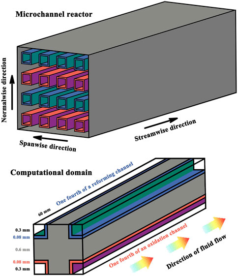
FIGURE 1. Schematic illustration of hydrogen production by a microchannel methanol reforming reactor with the computational domain indicated.
The parallel reaction channels are 60.0 mm in length. The reaction channels have a square cross-section, and the side length is 0.6 mm. The number of flow channels may vary depending upon the requirements of the application. At room temperature, the thermal conductivity, which indicates the ability to conduct heat, of the solid channel walls is 20 W/(m·K). The pressure of the reactant streams is 8 bars at the flow inlets, with a temperature of 100°C. The normalized ratio of fuel to air is 0.8 and the molar ratio of steam to carbon is 1.3. Therefore, both air and steam are present in excess. The premixed fuel-air mixture flows into the oxidation channels with a bulk velocity of 0.6 m/s and the reacting fluid reacts exothermically. Unless otherwise stated, the premixed fuel-steam mixture flows into the reforming channels with a bulk velocity of 2.0 m/s, at which the desired level of conversion can be attained for the reactants exiting the catalytically active channels, and the reactant fluid reacts endothermically. Under the velocity conditions specified above, the overall energy balance between the exothermic and endothermic reactions can be achieved within the reactor system; additionally, the reacting fluids enter the channels and the reaction products leave the reactor by the contact time in milliseconds (Schmidt et al., 2003). Contact time is defined as the total channel volume divided by the total volumetric flow rate at the reactor inlets (Tonkovich et al., 2007). Therefore, the thermal communication must be efficient by the thermally conductive path across the channel walls. The channel walls are made from stainless steel sheeting. The coatings applied to the interior channel walls are catalytically active, with a uniform distribution of active component. The channel walls and the catalyst coatings are 0.6 and 0.08 mm, respectively, in thickness.
2.2 Mathematical model
The physical model of the reactor system consists of catalytically active channel walls with the adjacent oxidation and reforming half-channels in a co-current flow configuration, and symmetry boundary conditions are used to increase computational efficiency. The mathematical model is solved numerically and implemented in the available commercial software package ANSYS FLUENT to obtain the solution to the problem involving reactions and transport, thereby permitting multi-dimensional computational modeling of chemical and physical phenomena in the complex processes. The conservation equations that determine reaction chemistry and fluid motion are solved numerically. Solutions of the governing partial differential equations can yield estimates of field variables, thus gaining valuable insights into the chemical and physical behaviors of the reactor system. Temperature-dependent and species-dependent thermochemical transport properties are included in the model on account of heat effects and differential diffusivity effects.
A continuity constraint is applied such that in each grid cell, the volume fractions of all gaseous species sum to unity. The continuity equation is given by
where x, y, and z denote coordinate variables, ρ is the density, and u is the velocity.
The momentum conservation equations are solved in the flow branches
where p is the pressure, and μ is the dynamic viscosity.
The energy conservation equation for the gas phases is solved at the grid nodes
where h is the enthalpy, k is the thermal conductivity, V is the diffusion velocity in the laminar reacting flow, T is the temperature, γ is the total number of gaseous species, and w is the mass fraction. The subscripts k and g denote gaseous species k and the gas mixture, respectively.
The species conservation equation is applicable:
where W is the molecular mass, and
The surface species conservation equation is given by
wherein
The energy conservation equation for the solid phase is solved at the grid nodes
where the subscript s denotes the solid walls.
The interfacial species conservation equations are solved at the solid-gas phase boundaries
where η is the effectiveness factor, α is the surface area factor, and ψ denotes the solid-gas phase boundaries. The effectiveness factor is a powerful way to account for mass transfer limitations on the reactions occurring within the catalyst coatings.
For the catalyst coatings, the effective diffusivity is given by the following formula:
where εp is the porosity, τp is the tortuosity factor, and Dm and DK are the molecular diffusivity and Knudsen diffusivity, respectively.
The Knudsen diffusivity is defined as
where d is the mean pore diameter.
For the catalyst coatings, the effective thermal conductivity k’ is defined as
The interfacial energy conservation equation is solved at the solid-gas phase boundaries
2.3 Chemical kinetic models
Steady calculation of oxidation and reforming reactions is achieved by incorporating directly complex chemistry into the model. The exothermic oxidation process is modeled by the kinetic model (Reitz et al., 2000b), and the endothermic reforming process is modeled by the kinetic model (Peppley et al., 1999). Calculations are conducted based on the complex chemical kinetics described above. These kinetic models allow multi-step reaction chemistry in the comparatively complex flow of interest for the reactor system. These kinetic models generally may produce reliable results and, in particular, offer detailed chemistry calculation. The rate of the oxidation reaction is expressed by partial pressures (Reitz et al., 2000b):
where r is the reaction rate.
For the endothermic steam reforming reaction, the chemical kinetics implemented in the model can be written as follows:
where
For the water-gas shift reaction, the rate equation can be written as
For the decomposition reaction, the chemical kinetics implemented in the model is given by
where the subscripts 2 and 2a denote the species index.
2.4 Model validation
Validation is necessary in order to improve and refine the model. Comparison with measurement data (Park et al., 2004; Park et al., 2005) is made to ensure the model reliability and calculation accuracy. In the experiment, the molar ratio of steam to methanol is 1.1, and a highly conductive material is used, which serves to ensure that the channel walls remain substantially isothermal. The conversion is performed at a channel wall temperature of 200, 220, 240, or 260°C, respectively, and at 1 atm pressure to produce hydrogen. The temperature is adjustable in 5°C equal increments. In the simulation, the isothermal wall boundary conditions are imposed on the model. The thermal boundary conditions at wall boundaries are defined by a fixed temperature to solve the energy equation in the fluid region. In this case, the temperature at the wall surface needs to be specified, and the two sides of the channel wall are not coupled thermally. Computer simulations are performed under the operation conditions used in the experiment. The productivity and conversion results predicted by the model and measured by the experiment are presented in Figures 2A, B, respectively, at different flow rates. The prediction results are in satisfactory agreement with the measurement data.
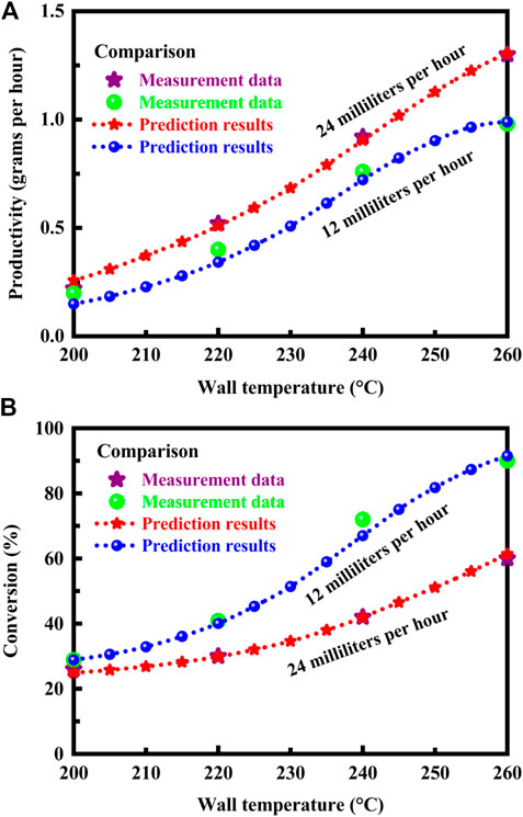
FIGURE 2. (A) Productivity predicted by the model and measured by the experiment at different flow rates. (B) Conversion predicted by the model and measured by the experiment at different flow rates. The data measured by the experiment (Park et al., 2004; Park et al., 2005) are presented for purposes of comparison.
3 Results and discussion
The structure of the microchannel reactor is illustrated in schematic detail in Figure 3A in different reforming catalyst porosity cases. The range of porosity in the catalysts is from 30 percent to 70 percent, and the overall catalyst porosity is maintained constant, 50 percent, in each case. The oxidation catalyst material exhibits a uniform porosity. This means that uniformity of porosity is maintained throughout the oxidation catalyst coating. In contrast, nonuniform porosities may be present in the reforming catalyst material. The following three reforming catalyst porosity cases are considered here: a uniform porosity, nonuniform porosities with a two-segment distribution, and nonuniform porosities with a three-segment distribution. The porosity varies in different segmented regions, but it is uniform in each region. The catalyst segments are of equal length in each porosity case. For the sake of simplicity, only the following five porosity cases are considered here for the reforming catalyst coating: (0.5); (0.3, 0.7); (0.7, 0.3); (0.3, 0.5, 0.7); and (0.7, 0.5, 0.3). The overall catalyst porosity is maintained constant in each case, as stated above. There is no need to segment the oxidation catalyst coating. The oxidation reaction is mass transfer limited. Maximum oxidation reaction rates of up to about 10 or more times the maximum reforming reaction rate are attainable. The oxidation reaction occurs very rapidly, consuming most of the methanol in the first half of the reactor. For mass-transfer controlled catalytic reactions, one cannot distinguish between a less active catalyst and a more active catalyst because the intrinsic catalyst activity is not determinative of the rate of reaction. Regardless of any increase in catalytic activity above that required for mass transfer control, a greater catalytic conversion rate cannot be achieved for the same set of conditions. The inlet velocity of the premixed methanol-steam mixture varies from 1.6 m/s to 3.0 m/s, and performance comparisons are made in terms of methanol conversion, hydrogen yield, heat of reaction, and dimensionless Nusselt and Sherwood numbers between these reforming catalyst porosity cases under different inlet velocity conditions.
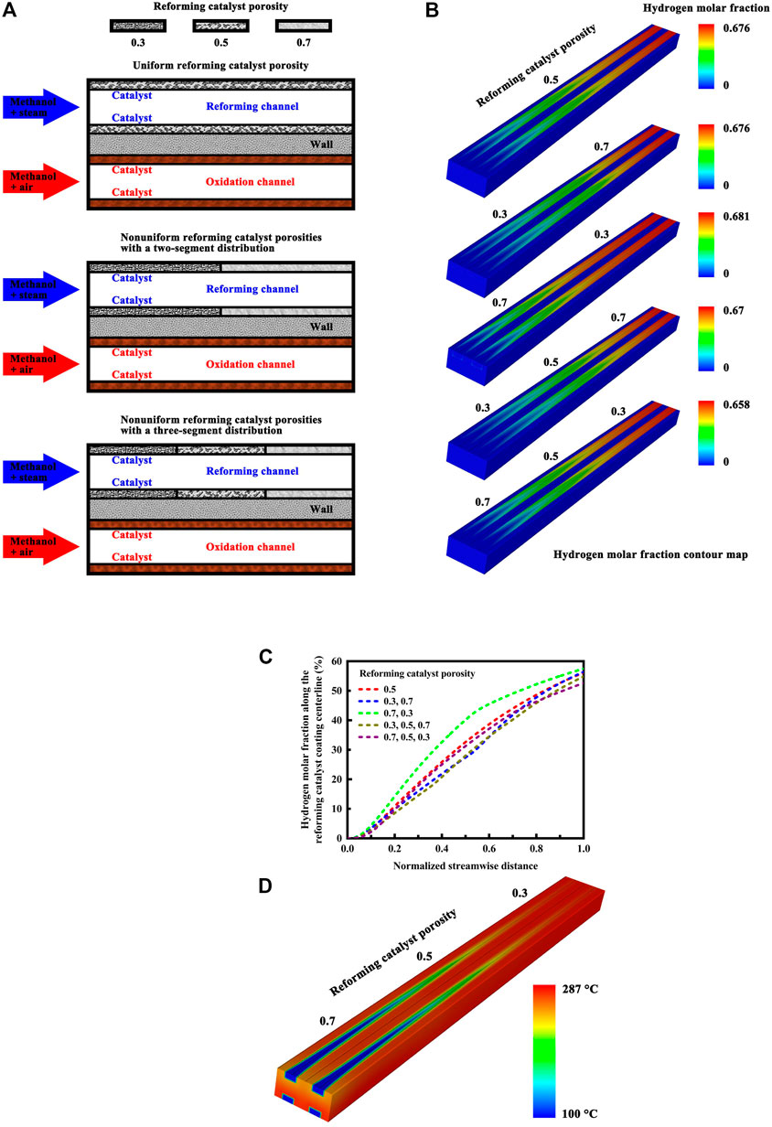
FIGURE 3. (A) Schematic illustration of the microchannel reactor structure in different reforming catalyst porosity cases. An illustrative example of different porosity cases is presented for the reforming catalyst coating: (0.5); (0.3, 0.7); and (0.3, 0.5, 0.7). (B) Hydrogen molar fraction contour map of the microchannel reactor with a uniform catalyst porosity or nonuniform reforming catalyst porosities under the normal inlet velocity conditions. (C) Hydrogen molar fraction profiles along the reforming catalyst coating centerline of the microchannel reactor under the normal inlet velocity conditions. (D) Temperature contour map of the microchannel reactor in a specific reforming catalyst porosity arrangement method under the normal inlet velocity conditions.
The hydrogen molar fraction contour map under the normal inlet velocity conditions is illustrated in Figure 3B for the microchannel reactor with a uniform catalyst porosity or nonuniform reforming catalyst porosities. The overall efficiency of the conversion process is high in each porosity case, but there is a considerable difference in the hydrogen concentration distribution in the reforming channels. For the following reforming catalyst porosity case: (0.7, 0.3), a higher porosity on the front side facilitates methanol conversion while a lesser porosity on the end side allows the reforming reaction to proceed further with higher conversion at the reactor outlet. However, the heat and mass transfer issues for the reactor system are highly complex. In a similar case: (0.7, 0.5, 0.3), for example, lower conversion of methanol to hydrogen is obtained at the reactor outlet, although the reforming catalyst has a higher porosity on the front side. The difference in methanol conversion between the other cases is small under the normal inlet velocity conditions. The heat transfer characteristics of the reactor may depend upon the flow velocity of the reforming reactants, since utilizing high gas velocities lead directly to increased inner heat transfer coefficients (Nouri-Borujerdi and Nakhchi, 2017; Serrano et al., 2022), thus improving the thermal effectiveness of the reactor system. Therefore, numerical simulations are performed under a variety of velocity conditions to evaluate the effect of reforming catalyst porosity arrangement on the transport phenomena in the reactor system for hydrogen production.
The hydrogen molar fraction profiles along the reforming catalyst coating centerline of the microchannel reactor are presented in Figure 3C under the normal inlet velocity conditions. For the following reforming catalyst porosity case: (0.7, 0.3), great advantages of improved hydrogen yield can be realized by using the two-segment design. However, the two-segment design yields no advantage if the reactor length is sufficient to provide essentially complete conversion or attain chemical equilibrium. The inlet velocity may also play an important role in taking the advantage of improved conversion and yield that the two-segment design offers, which is discussed in detail below. The temperature contour map of the microchannel reactor in a specific reforming catalyst porosity arrangement method is illustrated in Figure 3D under the normal inlet velocity conditions. Within the channel walls, there do exist large temperature gradients near the reactor entrance. The exothermic and endothermic reactions are closely coupled. Along the flow length of the channel wall that divides these reactions, the heat flux through the channel wall varies due to the differences in temperature and reaction rate along the flow direction. The three-segment design offers no advantage as discussed above, but the reactor still has temperatures sufficient to allow high conversion of methanol to hydrogen.
Calculations are performed using computational fluid dynamics and chemical kinetics over a range of velocities to fully investigate the influence of catalyst porosity arrangement on the methanol conversion, hydrogen yield per reforming channel, and heat of reaction per reforming channel. The results are presented in Figure 4 for the reactor operating at different inlet velocities of the methanol-steam mixture. The overall catalyst porosity is maintained constant, as noted above. The reforming reactant flow rate is varied so that the reactor operates under a variety of conditions. The flow rates of the reactants must be chosen to match the heat of the reactions. The reactor may operate at lower velocities to ensure complete conversion, as shown in Figure 4A. However, considerable velocities must be utilized, at which a sufficient mass of the methanol-steam mixture is available to absorb the heat of reaction with an increase in hydrogen yield, as shown in Figures 4B, C. For the boundary layers, the characteristic thickness is reduced at higher velocities. The optimum catalyst porosity arrangement depends upon the flow rates of the reactants, as discussed below. For the following reforming catalyst porosity case: (0.7, 0.3), a higher porosity on the front side facilitates conversion of methanol to hydrogen, produce a high yield of hydrogen, and effectively absorb the heat released by the exothermic oxidation reaction, if lower flow rates are employed for the reforming reactants at the reactor inlet. In contrast, at higher flow rates of the reforming reactants, the optimum catalyst porosity arrangement can be obtained for the following reforming catalyst porosity case: (0.3, 0.7). In this situation, the reforming reaction region shifts downstream with increasing the flow rate of the reforming reactants. The optimum catalyst porosity arrangement depends also upon the temperatures of the channel walls. The reactor may be tailored to suit the reforming reaction by adjusting parameters, such as the temperatures of the channel walls and the flow rates of the reforming reactants. Quite obviously, the former approach, while theoretically possible, is quite impractical. While considerable advantages can be realized by using the two-segment distribution method, the three-segment distribution method yields no advantage. More specifically, for the three-segment distribution method, there is a decrease in methanol conversion, hydrogen yield, and the amount of heat absorbed, as compared to those with the use of the uniform porosity distribution method, as shown in Figure 4. Consequently, the catalyst porosity arrangement methods can improve or degrade the reactor performance, depending upon the number of the catalyst segments employed for the reactor. Optimization of catalyst porosity arrangements is required for thermal matching purposes. For the thermally integrated microchannel reactor that is capable of performing different chemical reactions, the heat requirement should be matched to the heat generation in the adjacent channels. The reforming catalyst porosities must be configured to improve the kinetics in the upstream or downstream sections of the thermally integrated microchannel reactor so that the endothermic and exothermic processes are thermally matched, thereby improving the thermal efficiency of the reactor system.
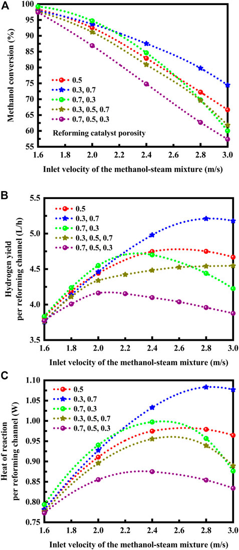
FIGURE 4. (A) Effect of reforming catalyst porosity arrangement on the conversion of methanol at different inlet velocities of the methanol-steam mixture. (B) Effect of reforming catalyst porosity arrangement on the hydrogen yield per reforming channel at different inlet velocities of the methanol-steam mixture. (C) Effect of reforming catalyst porosity arrangement on the heat of reaction per reforming channel at different inlet velocities of the methanol-steam mixture.
The physical and chemical processes involve considerations of mass and heat transport. Accordingly, the fundamental phenomena involved in the reactor depend upon the basic laws of mass and heat transport (Bizzi et al., 2002; Salmi et al., 2021). Transport performance and efficiency under different operation conditions can be compared using dimensionless numbers (Bizzi et al., 2002; Salmi et al., 2021). Dimensionless numbers are introduced in the model, thereby offering distinct advantages for the analysis of mass and heat transport. Dimensionless numbers are therefore constructed as ratios of variables. The reactor is characteristically concerned with dimensionless numbers. There are important dimensionless numbers in reactor design, including Reynolds, Nusselt, and Sherwood numbers.
To understand the underlying cause for the difference in reactor performance between the catalyst porosity arrangement methods, dimensionless Nusselt and Sherwood number analyses are carried out. The effect of reforming catalyst porosity arrangement on the mean Nusselt number is illustrated in Figure 5A at different inlet Reynolds numbers on the reforming side. Additionally, the Sherwood number profiles along the length of the reactor are presented in Figure 5B in different reforming catalyst porosity arrangement methods. The Nusselt number or dimensionless heat transfer coefficient can be written as follows (Rostami and Mortazavi, 1990; Hayes and Kolaczkowski, 1999):
in which Nu denotes the Nusselt number, h denotes the convective heat transfer coefficient, L denotes the characteristic length, and q denotes the local heat flux density.
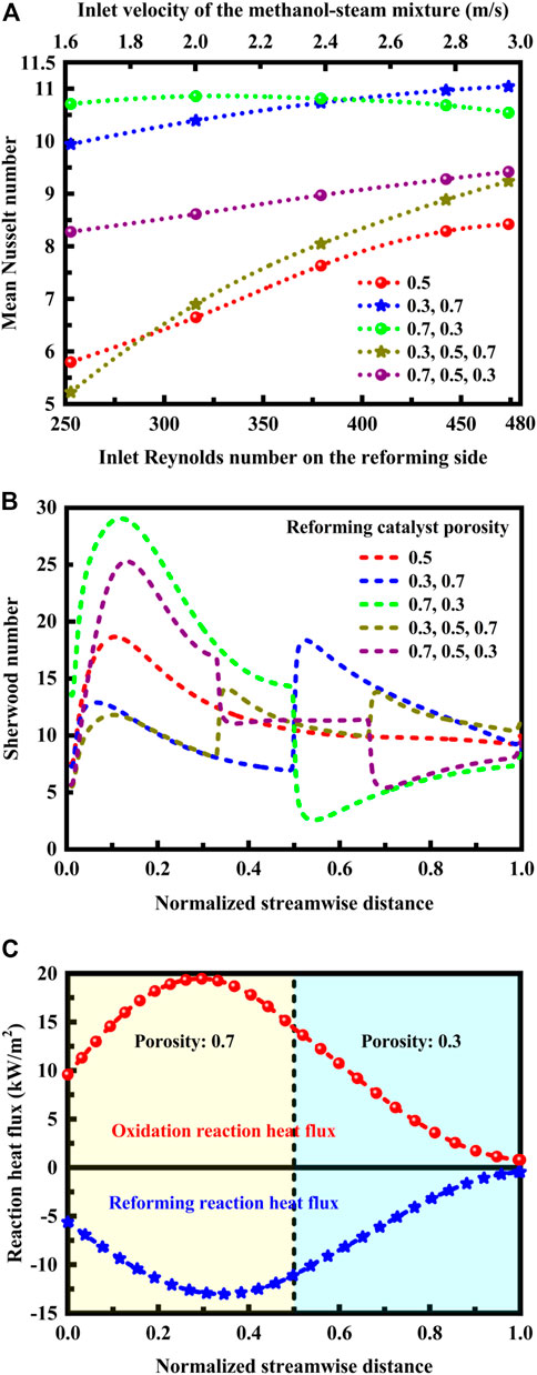
FIGURE 5. (A) Effect of reforming catalyst porosity arrangement on the mean Nusselt number at different inlet Reynolds numbers on the reforming side. The corresponding relationship between the inlet velocity and the inlet Reynolds number is indicated. (B) Effect of reforming catalyst porosity arrangement on the Sherwood number along the length of the reactor. (C) Heat flux profiles of the oxidation and reforming reactions along the length of the reactor in a specific reforming catalyst porosity arrangement method under the normal inlet velocity conditions.
The Sherwood number can be written as follows (Hayes and Kolaczkowski, 1994; Hayes et al., 2004):
in which Sh denotes the Sherwood number and
The Reynolds number is equal to the velocity of flow times the hydraulic diameter Dh times the density of the fluid divided by its dynamic viscosity
where Re denotes the Reynolds number and Dh denotes the hydraulic diameter. In all the cases studied, the inlet conditions, for example, inlet velocity, are typically used to calculate the Reynolds number.
The mean Nusselt number depends upon the inlet Reynolds number and the Sherwood number exhibits strongly nonmonotonic behavior, as shown in Figures 5A, B. The mean Nusselt number increases with the inlet Reynolds number on the reforming side in all the cases except the catalyst porosity arrangement method: (0.7, 0.3). In this case, a maximum Nusselt number can be achieved at lower flow rates of the reforming reactants. In contrast, in the catalyst porosity arrangement method: (0.3, 0.7), a maximum Nusselt number is obtained at higher flow rates of the reforming reactants. The results are entirely consistent with those presented in Figure 4, in which comparisons of reactor performance are made at different flow rates of the reforming reactants. On the other hand, for the following reforming catalyst porosity case: (0.7, 0.3), the maximum Sherwood number is achieved in the first half of the channels. In contrast, in the catalyst porosity arrangement method: (0.3, 0.7), the maximum Sherwood number is obtained in the last half of the channels. The Sherwood number represents the effectiveness of mass convection at the surface (van Zee et al., 1997; Sagiv et al., 1998). The flow rate of the reforming reactants may change the relative ratio of the maximum Sherwood numbers, which will eventually lead to the change of the mass transfer characteristics of the reactor.
It is necessary to understand how important the transverse transport components are. Accordingly, dimensionless Nusselt and Sherwood numbers are used to determine the relative strengths of the different transport phenomena within the reactor system, for example, whether or not conduction is more significant compared to convection, and whether or not heat diffuses quickly compared to velocity. In the transverse direction, convection resulting from variation of temperature and advection caused by variation of concentration is vital in determining the heat and mass transfer processes within the reactor system, as shown in Figures 5A, B. Specifically, the thermal energy convected to the fluid is much higher than that conducted within the fluid, especially in the catalyst porosity arrangement method: (0.7, 0.3) at lower flow rates, as shown in Figure 5A, since a larger Nusselt number corresponds to more effective convection. In this situation, the convective mass transfer to the mass diffusion, as shown in Figure 5B, since the Sherwood number represents the effectiveness of mass convection at the catalytically active surface.
The thermal behavior of the reactor is evaluated based upon reaction heat flux in order to understand the evolution of heat in the system. The heat flux profiles of the oxidation and reforming reactions along the length of the reactor in a specific reforming catalyst porosity arrangement method are presented in Figure 5C under the normal inlet velocity conditions. The reaction heat flux along the flow direction varies due to the differences in temperature and reaction rate. For the following reforming catalyst porosity case: (0.7, 0.3), the heat of reaction is thermally balanced within the reactor system. A higher porosity on the front side facilitates heat transfer while a lesser porosity on the end side allows the reforming reaction to proceed further with nearly complete conversion at the reactor outlet. The reaction heat flux for oxidation and reforming is positive and negative, respectively. The reaction heat flux for oxidation is positive, since the heat released by the oxidation reaction flows out of its region. The reaction heat flux for reforming is negative, since the heat consumed by the reforming reaction flows into its region. The positive heat flux is larger in magnitude than the negative heat flux, and therefore the net reaction heat flux is positive. There is a mathematical relation between heat flux and temperature gradient, depending upon the solid thermal conductivity. The total heat flux across the channel walls is proportional to the gradient of temperature within the channel walls. Several factors influence the operation of such an autothermal reactor. The factor considered here is the reforming catalyst porosity arrangement method. Further study is needed to optimize catalyst porosity arrangements by taking into account the effect of solid thermal conductivity.
4 Conclusion
Calculations are performed over a range of velocities to fully investigate the influence of catalyst porosity arrangement on the methanol conversion, hydrogen yield per reforming channel, and heat of reaction per reforming channel. To understand the underlying cause for the difference in reactor performance between the catalyst porosity arrangement methods, dimensionless Nusselt and Sherwood number analyses are carried out. The results indicate that the optimum catalyst porosity arrangement depends upon the flow rate of the reforming reactants. At lower flow rates, a higher porosity on the front side facilitates methanol conversion, produce a high hydrogen yield, and effectively absorb the heat of reaction. The reforming reaction region shifts downstream with increasing the flow rate, and thus the reactor performance can be improved a lesser porosity on the front side. The catalyst porosities must be configured to improve the kinetics in the upstream or downstream sections of the reactor so that the endothermic and exothermic processes are thermally matched. While advantages can be realized by using the two-segment distribution method, the three-segment distribution method yields no advantage. Consequently, the catalyst porosity arrangement methods can improve or degrade the reactor performance, depending upon the number of catalyst segments. Finally, the processes of transverse heat and mass transport are of great importance to the endothermic and exothermic reactions.
Data availability statement
The raw data supporting the conclusion of this article will be made available by the authors, without undue reservation.
Author contributions
JC contributed to conception and design of the study. JC and YY developed the model and performed the analysis. JC wrote the manuscript. All authors read and approved the submitted version. All authors read and approved the final manuscript. All authors contributed to the article and approved the submitted version.
Funding
This work was supported by the National Natural Science Foundation of China (No. 51506048).
Conflict of interest
The authors declare that the research was conducted in the absence of any commercial or financial relationships that could be construed as a potential conflict of interest.
Publisher’s note
All claims expressed in this article are solely those of the authors and do not necessarily represent those of their affiliated organizations, or those of the publisher, the editors and the reviewers. Any product that may be evaluated in this article, or claim that may be made by its manufacturer, is not guaranteed or endorsed by the publisher.
References
Abaidi, A. H., and Madani, B. (2021). Intensification of hydrogen production from methanol steam reforming by catalyst segmentation and metallic foam insert. Int. J. Hydrogen Energy 46 (75), 37583–37598. doi:10.1016/j.ijhydene.2020.12.183
Astarita, G. (1997). Dimensional analysis, scaling, and orders of magnitude. Chem. Eng. Sci. 52 (24), 4681–4698. doi:10.1016/s0009-2509(97)85420-6
Bart, J. C. J., and Sneeden, R. P. A. (1987). Copper-zinc oxide-alumina methanol catalysts revisited. Catal. Today 2 (1), 1–124. doi:10.1016/0920-5861(87)80001-9
Bizzi, M., Basini, L., Saracco, G., and Specchia, V. (2002). Short contact time catalytic partial oxidation of methane: Analysis of transport phenomena effects. Chem. Eng. J. 90 (1-2), 97–106. doi:10.1016/s1385-8947(02)00071-2
Borowiecki, T. (1987). Nickel catalysts for steam reforming of hydrocarbons: Direct and indirect factors affecting the coking rate. Appl. Catal. 31 (2), 207–220. doi:10.1016/s0166-9834(00)80691-0
Byun, M., Kim, H., Lee, H., Lim, D., and Lim, H. (2022). Conceptual design for methanol steam reforming in serial packed-bed reactors and membrane filters: Economic and environmental perspectives. Energy 241, 122516. Article Number: 122516. doi:10.1016/j.energy.2021.122516
Fan, L., Tu, Z., and Chan, S. H. (2021). Recent development of hydrogen and fuel cell technologies: A review. Energy Rep. 7, 8421–8446. doi:10.1016/j.egyr.2021.08.003
Hayes, R. E., and Kolaczkowski, S. T. (1999). A study of Nusselt and Sherwood numbers in a monolith reactor. Catal. Today 47 (1-4), 295–303. doi:10.1016/s0920-5861(98)00310-1
Hayes, R. E., and Kolaczkowski, S. T. (1994). Mass and heat transfer effects in catalytic monolith reactors. Chem. Eng. Sci. 49 (21), 3587–3599. doi:10.1016/0009-2509(94)00164-2
Hayes, R. E., Liu, B., Moxom, R., and Votsmeier, M. (2004). The effect of washcoat geometry on mass transfer in monolith reactors. Chem. Eng. Sci. 59 (15), 3169–3181. doi:10.1016/j.ces.2004.05.002
Herdem, M. S., Mundhwa, M., Farhad, S., and Hamdullahpur, F. (2019). Catalyst layer design and arrangement to improve the performance of a microchannel methanol steam reformer. Energy Convers. Manag. 180, 149–161. doi:10.1016/j.enconman.2018.10.094
Jacobs, A. F. G., and Welgraven, D. (1988). A simple model to calculate the Sherwood and Nusselt numbers for discs of various shapes. Int. J. Heat Mass Transf. 31 (1), 119–127. doi:10.1016/0017-9310(88)90228-1
Kang, J., Song, Y., Kim, T., and Kim, S. (2022). Recent trends in the development of reactor systems for hydrogen production via methanol steam reforming. Int. J. Hydrogen Energy 47 (6), 3587–3610. doi:10.1016/j.ijhydene.2021.11.041
Karagiannidis, S., Mantzaras, J., and Boulouchos, K. (2011). Stability of hetero-/homogeneous combustion in propane- and methane-fueled catalytic microreactors: Channel confinement and molecular transport effects. Proc. Combust. Inst. 33 (2), 3241–3249. doi:10.1016/j.proci.2010.05.107
Karagiannidis, S., Mantzaras, J., Jackson, G., and Boulouchos, K. (2007). Hetero-/homogeneous combustion and stability maps in methane-fueled catalytic microreactors. Proc. Combust. Inst. 31 (2), 3309–3317. doi:10.1016/j.proci.2006.07.121
Karim, G. A., and Metwally, M. M. (1980). A kinetic investigation of the reforming of natural gas for the production of hydrogen. Int. J. Hydrogen Energy 5 (3), 293–304. doi:10.1016/0360-3199(80)90073-7
Li, L., Chen, J., Zeng, C., Liu, Q., Hu, H., Huang, Q., et al. (2023). Preparation of CuZnZrAl catalysts by coprecipitation-ammonia method for methanol steam reforming and the effect of promoters Y and Ce. Mol. Catal. 537, 112887. Article Number: 112887. doi:10.1016/j.mcat.2022.112887
Lindström, B., and Pettersson, L. J. (2001). Hydrogen generation by steam reforming of methanol over copper-based catalysts for fuel cell applications. Int. J. Hydrogen Energy 26 (9), 923–933. doi:10.1016/s0360-3199(01)00034-9
Lytkina, A. A., Orekhova, N. V., Ermilova, M. M., Petriev, I. S., Baryshev, M. G., and Yaroslavtsev, A. B. (2019). Ru-Rh based catalysts for hydrogen production via methanol steam reforming in conventional and membrane reactors. Int. J. Hydrogen Energy 44 (26), 13310–13322. doi:10.1016/j.ijhydene.2019.03.205
Matsumura, Y. (2013). Enhancement in activity of Pd-Zn catalyst for methanol steam reforming by coprecipitation on zirconia support. Appl. Catal. A General 468, 350–358. doi:10.1016/j.apcata.2013.09.022
Mundhwa, M., Parmar, R. D., and Thurgood, C. P. (2017). A comparative parametric study of a catalytic plate methane reformer coated with segmented and continuous layers of combustion catalyst for hydrogen production. J. Power Sources 344, 85–102. doi:10.1016/j.jpowsour.2017.01.082
Mundhwa, M., and Thurgood, C. P. (2017). Numerical study of methane steam reforming and methane combustion over the segmented and continuously coated layers of catalysts in a plate reactor. Fuel Process. Technol. 158, 57–72. doi:10.1016/j.fuproc.2016.12.002
Nouri-Borujerdi, A., and Nakhchi, M. E. (2017). Optimization of the heat transfer coefficient and pressure drop of Taylor-Couette-Poiseuille flows between an inner rotating cylinder and an outer grooved stationary cylinder. Int. J. Heat Mass Transf. 108, 1449–1459. Part B. doi:10.1016/j.ijheatmasstransfer.2017.01.014
Ozturk, M., and Dincer, I. (2021). A comprehensive review on power-to-gas with hydrogen options for cleaner applications. Int. J. Hydrogen Energy 46 (62), 31511–31522. doi:10.1016/j.ijhydene.2021.07.066
Park, G.-G., Seo, D. J., Park, S.-H., Yoon, Y.-G., Kim, C.-S., and Yoon, W.-L. (2004). Development of microchannel methanol steam reformer. Chem. Eng. J. 101 (1-3), 87–92. doi:10.1016/j.cej.2004.01.007
Park, G.-G., Yim, S.-D., Yoon, Y.-G., Lee, W.-Y., Kim, C.-S., Seo, D.-J., et al. (2005). Hydrogen production with integrated microchannel fuel processor for portable fuel cell systems. J. Power Sources 145 (2), 702–706. doi:10.1016/j.jpowsour.2005.01.080
Patel, S., and Pant, K. K. (2006). Activity and stability enhancement of copper-alumina catalysts using cerium and zinc promoters for the selective production of hydrogen via steam reforming of methanol. J. Power Sources 159 (1), 139–143. doi:10.1016/j.jpowsour.2006.04.008
Peppley, B. A., Amphlett, J. C., Kearns, L. M., and Mann, R. F. (1999). Methanol-steam reforming on Cu/ZnO/Al2O3 catalysts. Part 2. A comprehensive kinetic model. Appl. Catal. A General 179 (1-2), 31–49. doi:10.1016/s0926-860x(98)00299-3
Ramaswamy, R. C., Ramachandran, P. A., and Duduković, M. P. (2008). Coupling exothermic and endothermic reactions in adiabatic reactors. Chem. Eng. Sci. 63 (6), 1654–1667. doi:10.1016/j.ces.2007.11.010
Ramaswamy, R. C., Ramachandran, P. A., and Duduković, M. P. (2006). Recuperative coupling of exothermic and endothermic reactions. Chem. Eng. Sci. 61 (2), 459–472. doi:10.1016/j.ces.2005.07.019
Rasul, M. G., Hazrat, M. A., Sattar, M. A., Jahirul, M. I., and Shearer, M. J. (2022). The future of hydrogen: Challenges on production, storage and applications. Energy Convers. Manag. 272, 116326. Article Number: 116326. doi:10.1016/j.enconman.2022.116326
Reitz, T. L., Ahmed, S., Krumpelt, M., Kumar, R., and Kung, H. H. (2000). Characterization of CuO/ZnO under oxidizing conditions for the oxidative methanol reforming reaction. J. Mol. Catal. A Chem. 162 (1-2), 275–285. doi:10.1016/s1381-1169(00)00296-x
Reitz, T. L., Ahmed, S., Krumpelt, M., Kumar, R., and Kung, H. H. (2000). Methanol reforming over CuO/ZnO under oxidizing conditions. Stud. Surf. Sci. Catal. 130, 3645–3650.
Rostami, A. A., and Mortazavi, S. S. (1990). Analytical prediction of Nusselt number in a simultaneously developing laminar flow between parallel plates. Int. J. Heat Fluid Flow 11 (1), 44–47. doi:10.1016/0142-727x(90)90023-5
Ruzicka, M. C. (2008). On dimensionless numbers. Chem. Eng. Res. Des. 86 (8), 835–868. doi:10.1016/j.cherd.2008.03.007
Rywik, M., Kasthuri, P., Boxx, I., Chterev, I., Polifke, W., and Sujith, R. I. (2022). Turbulence and heat release rate network structure in hydrogen-enriched combustion. Proc. Combust. Inst. In Press. doi:10.1016/j.proci.2022.08.053
Sá, S., Silva, H., Brandão, L., Sousa, J. M., and Mendes, A. (2010). Catalysts for methanol steam reforming-A review. Appl. Catal. B Environ. 99 (1-2), 43–57. doi:10.1016/j.apcatb.2010.06.015
Sagiv, A., Brosh, A., and Ecker, G. Z. (1998). Effect of Sherwood number on critical constants of diffusion. Int. J. Heat Mass Transf. 41 (12), 1729–1738. doi:10.1016/s0017-9310(97)00252-4
Salmi, T., Russo, V., and Aguilera, A. F. (2021). Modelling of the interaction of kinetics and external transport phenomena in structured catalysts: The effect of reaction kinetics, mass transfer and channel size distribution in solid foams. Chem. Eng. Sci. 244, 116815. Article Number: 116815. doi:10.1016/j.ces.2021.116815
Schmidt, L. D., Klein, E. J., Leclerc, C. A., Krummenacher, J. J., and West, K. N. (2003). Syngas in millisecond reactors: Higher alkanes and fast lightoff. Chem. Eng. Sci. 58 (3-6), 1037–1041. doi:10.1016/s0009-2509(02)00645-0
Serrano, D., Sánchez-Delgado, S., Pérez-Álvarez, R., and Acosta-Iborra, A. (2022). Experimental determination of the convection heat transfer coefficient in an eccentric annular duct. Exp. Therm. Fluid Sci. 136, 110664. Article Number: 110664. doi:10.1016/j.expthermflusci.2022.110664
Shoji, K., Hirota, Y., and Numaguchi, T. (1999). Development of highly active nickel catalyst for steam natural gas reforming. Stud. Surf. Sci. Catal. 121, 449–452.
Sohn, H. Y. (1977). The limiting Sherwood and Nusselt numbers in sphere-packed beds. Lett. Heat Mass Transf. 4 (6), 403–415. doi:10.1016/0735-1933(77)90040-9
Tonkovich, A. L. Y., Yang, B., Perry, S. T., Fitzgerald, S. P., and Wang, Y. (2007). From seconds to milliseconds to microseconds through tailored microchannel reactor design of a steam methane reformer. Catal. Today 120 (1), 21–29. doi:10.1016/j.cattod.2006.07.022
Trimm, D. L. (1988). The steam reforming of natural gas: Problems and some solutions. Stud. Surf. Sci. Catal. 36, 39–50.
van Zee, G., Bisschops, M., and De Graauw, J. (1997). Internal Sherwood numbers for diffusion in sorption operations. Chem. Eng. Process. Process Intensif. 36 (3), 201–208. doi:10.1016/s0255-2701(97)00001-9
Verhelst, S. (2014). Recent progress in the use of hydrogen as a fuel for internal combustion engines. Int. J. Hydrogen Energy 39 (2), 1071–1085. doi:10.1016/j.ijhydene.2013.10.102
Wang, Q.-H., Yang, S., Zhou, W., Li, J.-R., Xu, Z.-J., Ke, Y.-Z., et al. (2018). Optimizing the porosity configuration of porous copper fiber sintered felt for methanol steam reforming micro-reactor based on flow distribution. Appl. Energy 216, 243–261. doi:10.1016/j.apenergy.2018.02.102
Wang, Y., Diaz, D. F. R., Chen, K. S., Wang, Z., and Adroher, X. C. (2020). Materials, technological status, and fundamentals of PEM fuel cells - a review. Mater. Today 32, 178–203. doi:10.1016/j.mattod.2019.06.005
Wang, Y., Yuan, H., Martinez, A., Hong, P., Xu, H., and Bockmiller, F. R. (2021). Polymer electrolyte membrane fuel cell and hydrogen station networks for automobiles: Status, technology, and perspectives. Adv. Appl. Energy 2, 100011. Article Number: 100011. doi:10.1016/j.adapen.2021.100011
Xu, Z.-J., Yang, S., Hu, G.-H., Wang, Q.-H., and Li, J.-R. (2018). Numerical study of flow distribution uniformity for the optimization of gradient porosity configuration of porous copper fiber sintered felt for hydrogen production through methanol steam reforming micro-reactor. Int. J. Hydrogen Energy 43 (9), 4355–4370. doi:10.1016/j.ijhydene.2018.01.083
Yang, Y., Tong, L., Yin, S., Liu, Y., Wang, L., Qiu, Y., et al. (2022). Status and challenges of applications and industry chain technologies of hydrogen in the context of carbon neutrality. J. Clean. Prod. 376, 134347. Article Number: 134347. doi:10.1016/j.jclepro.2022.134347
Zanfir, M., and Gavriilidis, A. (2003). Catalytic combustion assisted methane steam reforming in a catalytic plate reactor. Chem. Eng. Sci. 58 (17), 3947–3960. doi:10.1016/s0009-2509(03)00279-3
Keywords: microchannel reactors, hydrogen production, computational modeling, steam reforming, thermal management, transport phenomena
Citation: Chen J and Yu Y (2023) Brief research report optimization of catalyst porosity arrangements for hydrogen production in microchannel reactors by methanol reforming. Front. Energy Res. 11:1177623. doi: 10.3389/fenrg.2023.1177623
Received: 01 March 2023; Accepted: 04 May 2023;
Published: 15 May 2023.
Edited by:
Haochun Zhang, Harbin Institute of Technology, ChinaReviewed by:
Qiang Ma, Jiangsu University, ChinaManfred Kraut, Karlsruhe Institute of Technology (KIT), Germany
Copyright © 2023 Chen and Yu. This is an open-access article distributed under the terms of the Creative Commons Attribution License (CC BY). The use, distribution or reproduction in other forums is permitted, provided the original author(s) and the copyright owner(s) are credited and that the original publication in this journal is cited, in accordance with accepted academic practice. No use, distribution or reproduction is permitted which does not comply with these terms.
*Correspondence: Junjie Chen, Y2pqQGhwdS5lZHUuY24=