 Xudong Wu
 Shibo Wang1,2*
 Qingtai Xiao
- 1State Key Laboratory of Complex Nonferrous Metal Resources Clean Utilization, Kunming University of Science and Technology, Kunming, Yunnan, China
- 2Engineering Research Center of Metallurgical Energy Conservation and Emission Reduction, Ministry of Education, Kunming University of Science and Technology, Kunming, Yunnan, China
- 3Southwest Copper Branch of Yunnan Copper Co., Ltd., Kunming, Yunnan, China
In view of the gas-liquid two-phase flow process in the oxygen-enriched side-blown molten pool, the phase distribution and manifold evolution in the side-blown furnace under different working conditions are studied. Based on the hydrodynamics characteristics in the side-blown furnace, a multiphase interface mechanism model of copper oxygen-enriched side-blown bath melting was established. The results show that the existence of slag baffle makes the velocity distribution range of melting mixing zone wider, the mixing range of melt wider, the mixing effect better, and the role of melting zone strengthened. The average speed of case MY in the melting zone is the highest, nearly 5.2% higher than that of case EY, and 16.7% higher than that of case EN. Compared with the average turbulent kinetic energy in the melting zone, case MY has a significant advantage of 2.635 m2/s2, which is increased by 47%, 34%, and 14% respectively compared with case EN, case EY, and case MN.
1 Introduction
Oxygen enrichment Molten Pool melting process, originated from Vanukov smelting process, has many advantages, including strong suitability of raw material, cheap capital cost, stable production and low energy consumption. During the smelting process, the copper concentrate is continuously put into the molten pool from the feeding port on the top of the furnace, and the oxygen-rich air is continuously drummed into the slag layer through the tuyeres on both sides, and provides stirring kinetic energy for the melt (Zhong et al., 2010a; Zhou et al., 2015; Liu et al., 2018). In recent years, with rising demand for copper products, the amount of copper necessary to meet demand rises year after year, and the copper feed concentrate quantity of side-blown smelting furnaces has also increased. In fact, the large-scale side-blown smelting furnace poses a great challenge to the existing smelting equipment and operation process. The extension of the furnace body leads to the uneven momentum transfer of the molten pool, the instability of the convection of copper matte and copper slag, and the insufficient clarification of the slag matte separation in the slag chamber. Therefore, it is of great significance to study the basic characteristics of high-speed gas side-blown jet and the phenomenon of momentum, mass and energy transfer during its injection process. Many studies on the thermodynamics and reaction kinetics of the Molten Pool melting process have been carried out in related fields; however, there are limited studies on phase distribution and manifold evolution in flow field (Chen et al., 2015; Chen et al., 2020), which are also essential and need to be studied in detail.
The phase distribution and manifold evolution in molten pool melting process are difficult to observe, because of the high temperature and chemical reactions in the metallurgical furnace. In order to understand the distribution of flow field, temperature field and concentration field in the furnace and the influence of gas jet on the stability of the molten pool, many scholars have studied it by means of water model experiment. Zhong et al. (2010b) compared the mixing time of the molten bath with separate side-blown gas flows, indicating that there was a critical value for the side-blown gas flow rate. When the gas flow rate is lower than the critical value, the mixing time decreases significantly with the increase of side blowing gas flow rate. Cheng et al. (2014); Zhou et al. (2016) recorded the gas side-blown flow process by high-speed camera, and systematically studied the influence of gas flow rate, liquid viscosity, and nozzle diameter on the bubble departure frequency and gas penetration depth. The SBS process was innovatively analyzed using the flow field distribution in different regions within the water model by Xiao et al. (2023). Liu et al. (2017) studied the variation of the penetration behavior of the side blowing gas in the liquid by employing the imaging technique, and established a more reliable trajectory model to describe the immersed side-blown gas jet in the liquid based on the force of a single bubble.
Water and air are the principal materials to mimic the melt and the oxygen-containing gas, respectively (Zhao et al., 2019; Li et al., 2020; Rodrigues Hendy et al., 2021). The hydrodynamics analysis of the side-blown vortex smelting reduction reactor by the water model experiment helps to study the effect of operating parameters such as nozzle diameter, the number of lances, and total gas flow rate on the local bubble characteristics and gas–liquid interaction. However, the water model experiment also has many disadvantages, such as large experimental error, poor continuity of extraction results, difficult operation under thermal conditions (Obiso et al., 2019; Obiso et al., 2020).
With the development of computer technology, numerical simulation provides a new method to study fluid flow in metallurgical process. Some scholars use the VOF model to simulate the flow of air mass, and believe that the air mass is deformable and can simulate the free surface of the air mass (Rabha and Buwa, 2010; Xiaolong and Enhua, 2010; Yan et al., 2014). The experimental results show that the VOF model can be utilized to predict and characterize the formation of impact pits and the fluctuation of the liquid surface, and it has excellent performance in predicting the breakup of gas jet and the trajectory of large bubbles in fluid. Liu et al. (Yan-ting et al., 2020). used three different turbulence models for the simulation of the turbulent gas−liquid flow in the container, calculated the jet penetration depth and surface fluctuation height of the nozzle axis under different models, and compared with the experimental results. They found that the numerical results with the realizable k-ε turbulence model were the closest to the experiment.
In the copper industry, the multiphase flow parameters of high temperature fluid in furnace are not only related to the efficiency of metallurgical reaction, but also determine the safe service life of metallurgical furnace. Xiao et al. (2021) simulated the gas-slag-matte three-phase flow in the side-blown furnace, and proposed three improved gas injection methods to improve the flow field of the weak-loop zone in the center of the molten bath. Of these methods, the oblique injection mode showed the best improvement effect. The kinetic energy of the injected gas is more used to stir the molten pool than to form large bubbles to cause splashing.
In the above work, there are few studies on the multiphase flow process in the side-blown bath smelting process, and mainly focus on the distribution and improvement of the spray gun, which cannot solve the problems brought about by the large-scale side-blown furnace. In addition, in many numerical simulation studies, in order to simplify the experimental device, researchers usually only set a pair of nozzles, ignoring the slag chamber and slag discharge port. This scheme which does not contribute to the design optimization of side-blown furnace, does not observe the interaction between gas jets. In this paper, the multiphase flow in side-blown furnace is simulated by numerical simulation, and the phase distribution and manifold evolution in side-blown furnace under different conditions are analyzed. Combined with the hydrodynamic characteristics in the side-blown furnace, a multiphase interface mechanism model of copper oxygen-rich side-blown bath smelting was established. The structure of side—blown furnace was optimized by comparing the influence of installation position of slag discharge chamber on the stability of slag layer and matte layer.
2 Model establishment
2.1 Geometry and mesh model
Figure 1 shows the geometry of an oxygen-enriched side-blown furnace with a size of 7.5 × 4 × 6.75 m, which can be roughly divided into three regions: the upper flue gas region, the middle slag phase region and the bottom metal phase region. In order to accurately simulate the flow phenomenon in the furnace and reduce unnecessary interference factors, the physical model was simplified during the research process. The two-phase flow process in the region below the slag liquid level in the furnace is the core content of the study, and it is not necessary to pay attention to the top flue gas flow. Therefore, the flue gas baffle and secondary air outlet are ignored. Because the nozzle in the distance has little impact on the flow field in the settling zone, only six pairs of nozzles and a slag chamber were included in the computational area. The specific structure and size are shown in Figure 2A. The overflow port is set on the wall of the slag chamber, which is connected with the external overflow tank through the flow channel to consider the difference between the middle slag discharge and the end slag discharge. The round nozzle was equivalent to a square according to the nozzle cross-sectional region to improve the mesh quality of the joint between the nozzle and the furnace wall. Due to the irregular shape of the calculation area, the mesh structure of the whole calculation area is hexahedron/wedge mesh structure, as shown in Figure 2B.
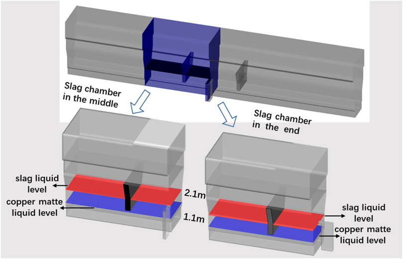
FIGURE 1. Schematic diagram of oxygen-enriched side-blown furnace body structure.
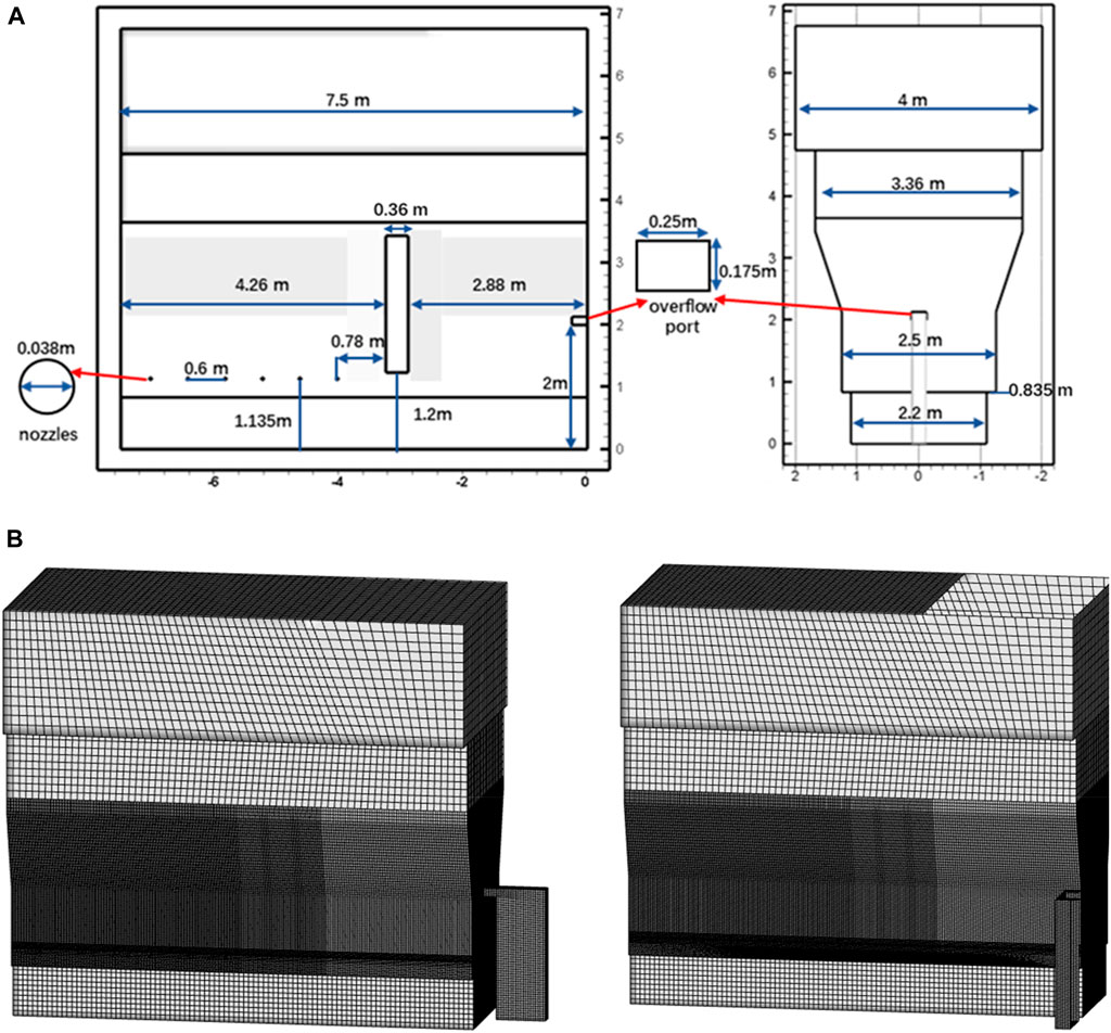
FIGURE 2. Physical model and mesh division of numerical simulation. Physical model (A) and mesh division (B) of numerical simulation.
The following simplifications and assumptions are adopted in this study:
1. Ignore the chemical reactions occurring in the molten pool of the side-blown furnace,
2. Furnace feeding, slag and other factors are not considered.
2.2 Mathematical model of the gas-liquid flows
The side-blown bath smelting process involves gas–slag–matte three-phase flow, and the interfacial phenomenon was numerically simulated by the VOF multiphase model coupled to the realizable
2.2.1 Transport equations
The phase interface between multiphases is traced by solving the continuity equation of multiphase volume fraction. For the
In the formula,
In the VOF model, the velocity field is obtained by solving a single momentum equation in the entire region, and the velocity field is shared by the phases as a calculation result. The momentum equation depends on the
In the formula,
In the VOF model, the energy equation is expressed as follows:
In the formula,
For multiphase systems, all properties are calculated based on the average volume fraction. The expressions of density and viscosity are:
2.2.2 Turbulence model
The Realizable
The turbulent kinetic energy
The turbulent energy dissipation rate
where
and
where
2.3 Physical parameters and boundary conditions
The main physical parameters used in the simulation calculation are shown in Table 1. The gas phase was oxygen-enriched air with oxygen content of 85%, which is set as incompressible ideal gas. The physical parameters of slag and copper matte under high temperature melting state were provided by the copper smeltery. Under the initial conditions of numerical simulation, the temperature of the melt phase was 1,573.15 K, and the temperature of the primary air inlet flow was 293.15 K.

TABLE 1. Main physical parameters.
The nozzles were set to the velocity–inlet boundary condition. The flow velocity at the nozzle was 163.5 m/s, and the turbulence intensity was calculated to be 3.16% according to the flow velocity and hydraulic diameter. The pressure–outlet boundary condition was used at the top outlet of the exhaust gas and the slag overflow channel, and the pressures were set as −10 and 0 Pa, respectively.
Pressure-velocity coupling was implemented with SIMPLE algorithm, and the governing equations of continuity, momentum, and turbulence were governed by a second-order upwind difference scheme. All the residuals were converged to 10–3, the time step was set to 10–4, and the Courant number range is within 1.0–2.1.
In order to verify the independence of the mesh, the time required for the first batch of bubbles to reach the liquid level in side-blown furnace was taken as the research object, and models with different mesh numbers were simulated.
As shown in Figure 3, there is still a significant deviation between the simulation results with the mesh number of 1.5 million and 2 million, but the results after 2 million meshs are basically consistent, approaching 0.792 s. Based on the above results, the number of meshs is finally determined to be 2 million, which can not only ensure the mesh quality, but also improve the efficiency of simulation calculation.
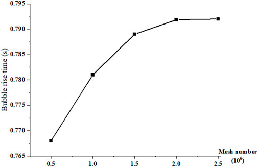
FIGURE 3. Mesh independence study.
2.4 Model verification
The water model experimental verification platform built in this study is shown in Figure 4. The main experimental instruments include: controller, air compressor, gas storage tank, flowmeter, high-speed camera, and side-blown furnace. According to the modifying Froude number, when the industrial speed is 163.5 m/s, the corresponding water model gas flow rate is 8 L/min.
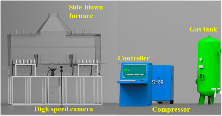
FIGURE 4. Side-blown furnace water model test platform.
The mixing and stirring of gas-liquid two-phase flow in side-blown furnace water model test device was photographed by high-speed camera. As shown in Figure 5, the captured images are compared with the simulation results. In Figures 5A, B, the gas expands in the horizontal direction. In Figures 5C, D, As the bubbles rise along the furnace wall, the pressure distribution inside the bubbles is uneven, resulting in a cap shaped overall shape. In Figures 5E, F, the gas no longer polymerizes to form large bubbles, presenting a columnar structure as a whole. The bubble motion behavior captured by the water model experiment is consistent with the results of numerical simulation, which verifies the reliability of the water model, and also confirms the accuracy and feasibility of a series of solving methods adopted by the mathematical model established in the numerical simulation.
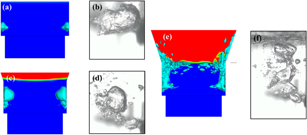
FIGURE 5. Comparison of jet pattern in the simulation and experiment.
In addition, the dimensionless distance which was calculated according to Eq. 11 is another basis to verify the accuracy of the model.
where
In the process of gas-liquid two-phase side-blown, the dimensionless distance is 10–20 when the velocity basically disappears (Zhu et al., 2022). In the simulation results, when the dimensionless distance is 12.8, the forward velocity on the nozzle shaft basically disappears, which is consistent with the experimental conclusion.
In summary, the consistency between prediction and measurement is considered good.
3 Results and discussion
In the side-blown smelting process, intense chemical reactions occur among multiple components in the furnace. The mineral material and oxygen produce a violent stirring effect on the melt to achieve rapid mixing and redox reaction. In order to intuitively understand the mechanism of side-blown smelting process, a multiphase interface mechanism model of copper oxygen-rich side-blown bath smelting was established on the basis of SKS process mechanism (Wang et al., 2017) by combining the hydrodynamic characteristics in the side-blown furnace with the thermodynamics of copper metallurgical process, as shown in Figure 6.
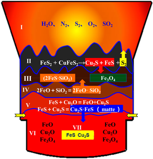
FIGURE 6. Mechanism model of oxygen side blowing copper smelting.
In the model, the cross section of the furnace melting zone is divided into four main layers from top to bottom and from outside to inside, which are flue gas layer, mineral decomposition transition layer, slag layer and copper matte layer. The slag layer is subdivided into slag layer and slag formation transition layer, copper matte layer can be subdivided into matte transition layer, strong oxide layer and weak oxide layer. These layers and regions play different roles in the smelting process.
In the matte transition layer, due to the influence of high temperature, the affinity of Cu for sulfur is greater than that of iron, while the affinity of iron for oxygen is greater than that of copper, so the following reactions can occur:
According to current thermodynamic viewpoints, it can be considered that the differences in oxygen potential and sulfur potential between different melts in the copper melting process promote the occurrence of chemical reactions and promote the development of the melting process.
Combined with the mechanism model and the furnace structure, it can be seen that the matte transition layer is located near the matte slag interface and above and below the horizontal line of the side-blowing gun jet inlet. By stirring the matte transition layer with gas, the partial pressure of the reactants can be greatly enhanced, the chemical reaction can be carried out normally, and the smelting efficiency can be improved.
In this study, a new structure of side-blown furnace was proposed. The slag chamber at the end of the furnace was retrofitted in the middle, and the molten pool was partitioned by slag baffle wall to convert a long smelting area into two short smelting areas. This design solves the problem of uneven momentum transfer caused by the long furnace body, and successfully realizes the dynamic strengthening smelting and static slag matte separation process in a furnace. As shown in Table 2, four different furnace types are proposed to study the phase distribution and flow pattern evolution in the stirring melting zone and the settling static zone during the side blowing process, and the influence of the installation position of the slag removal chamber on the stability of the slag layer and matte layer is obtained.
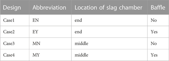
TABLE 2. Design schemes of different furnace types.
3.1 Phase distribution
Gas holdup is an important parameter to characterize gas-liquid two-phase fluid mechanics, which has an important influence on gas-liquid contact area, reaction rate and other fluid mechanics parameters. Taking case EN as an example, the gas phase distribution in the stirring melting zone of a side blown furnace at 3 s was analyzed.
Figure 7A shows spatial distribution of the iso-surface of the volume fraction of gas phase (Vf = 0.05) of the smelting zone. It can be seen that the gas in the slag layer presents a bubble or gas column shape, and the diffusion degree is not large during the rising process.
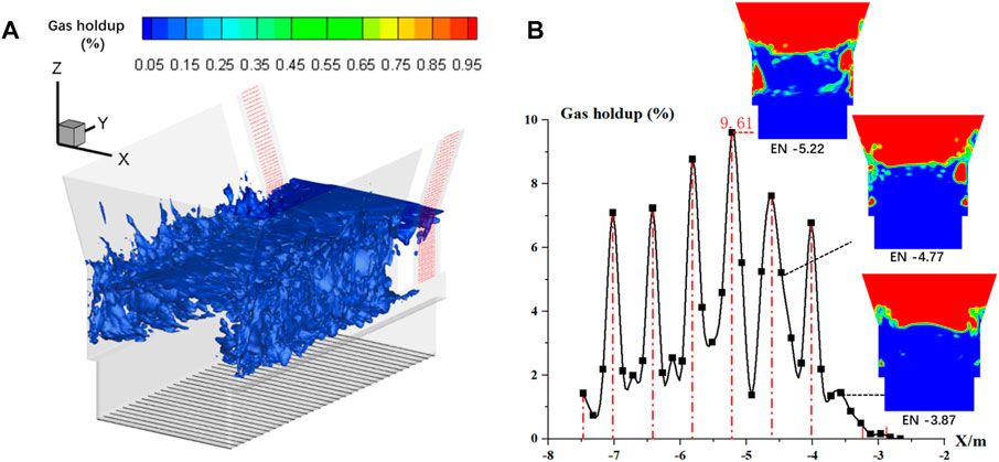
FIGURE 7. Change curve of gas phase distribution (A) and gas phase volume fraction along the furnace length in the stirring zone of the molten pool (B).
As shown in Figure 7B, the distribution of the gas phase is mainly concentrated in the small area directly above the tuyere. The gas holdup in the stirring zone shows a distribution of high in the middle and low on both sides along the length of the furnace. The peak value appears on the cross section X = −5.22 m in the furnace length direction, which is located on the central axis of the fourth nozzle, and the gas holdup is 9.61%. The gas holdup fluctuates in the molten pool, which is related to the distribution of the nozzle. On the section near the nozzle, the gas holdup is larger, while on the section away from the nozzle, the gas holdup is smaller. In this case, the reaction intensity at the center of the molten pool will be more intense, and the two ends will be relatively weak. The continuous introduction of oxygen-rich air makes the gas in the molten pool always maintain this distribution. At the same time, if there is no baffle, some oxygen-rich gas may escape to the settling area, destroy the flow field balance in the settling area, and reduce the separation efficiency of slag matte.
As shown in Figure 8, the change trends of gas holdup along the furnace height direction under different cases are basically similar. The cross section at height Z = 1.1 m is located below the tuyere, so the gas content is low. The large kinetic energy of the high-speed jet entering the molten pool through the spray gun makes the bubble movement mainly horizontal penetration, so the longitudinal floating trend of the bubble is not obvious. The gas holdup reaches the first small peak on the cross section of Z = 1.2 m. When the bubble volume exceeds the maximum equilibrium value, the bubble begins to move obliquely upward under the combined action of inertia and buoyancy, and the gas holdup continues to decline in the height range of 1.2–1.5 m, reaching the bottom at a height of 1.5 m. The gas content in the upper layer of the slag layer above 1.5 m is significantly improved, which is due to the involvement of a part of the flue gas during the violent splashing. In addition, the gas holdups at each height for case EY and case MY are always higher than the results under case EN and case MN.
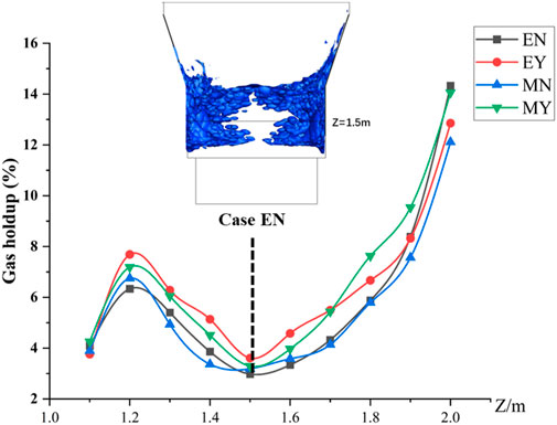
FIGURE 8. Variation curve of gas phase volume fraction along furnace height at 3 s under four cases.
Under the bubble flow mechanism, the bubble is greatly disturbed by the melt during the rising process, and it is easy to aggregate into a larger air mass under the action of the flow field. In this case, although the overall gas holdup of the melt is high, the stirring efficiency is poor. Therefore, the gas holdup cannot be used as a single standard to determine the mixing effect in the side-blown furnace.
3.2 Flow pattern evolution
As mentioned above, the stronger the agitating capacity of the slag layer, the better the partial pressure of matte reactants, the higher the probability of matte droplet collision, and the matte droplet agglomeration and enrichment to the bottom matte layer. For the fluid in the settling zone, the industrial requirement is not too much fluctuation, otherwise the static separation of the matte in the slag will be destroyed, and the matte phase in the slag will increase, resulting in copper loss.
Therefore, for the melting region, the higher velocity and turbulent kinetic energy are naturally pursued, while the sedimentation region wants to keep it in a static state.
In order to study the flow characteristics of the slag in the solution pool during the side-blown process, several sections are taken, as shown in Figure 9A, to observe the fluid velocity distribution on the sections at different heights.
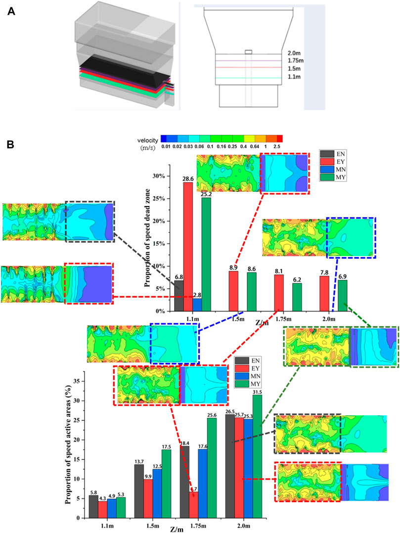
FIGURE 9. Division of height sections (A) and distribution of velocity active and dead zones (B) at 3 seconds under four cases.
The region with a speed less than 0.01 m/s is defined as the speed dead zone, and the region with a speed greater than 0.4 m/s is defined as the speed active zone. As shown in Figure 9B, at the height of Z = 1.1 m (slag/matte interface), the dead zone area of working condition EY is the highest, accounting for 28.6%, and the dead zone area of working condition MY is the lowest, accounting for 2.8%, which is nearly 10 times the difference. As the height increases, the slag baffle begins to function. Since there are no baffle constraint, the kinetic energies of the smelting zone in case EN and case MN dissipate into the settling zone. There is no mixing dead zone in the flow field for the two cases. At a height of Z = 1.1 m, the melt is less affected by gas injection and is only slightly affected by the jet wake in a small area directly below the tuyere, and the proportions of velocity active zone are less than 6%. At the height of Z = 2.0 m, the active area of case MY accounted for the highest proportion of 31.5%. There is almost no low-speed region in the stirring smelting zone, indicating that the melt is disturbed violently here, thereby increasing the contact area between the airflow and the melt, which is conducive to the occurrence and progress of the reaction.
Figure 10 shows the variation curves of the average phase velocity (average areal velocity) at different heights along the furnace body under 4 cases at 3 s. The average velocities at each height for case EY and case MY are always higher than the results under case EN and case MN. At the height of Z = 1.2 m, the high-speed jet just enters the molten pool and contacts with the slag. Due to the resistance of the slag, the kinetic energy of the gas is converted into the potential energy of the melt flow, and the gas velocity decreases rapidly. There is only a peak here. Under the action of buoyancy, the gas jet diffuses into the upper space of the molten pool. As the height increases, the melt on the upper part of the slag layer is disturbed by rising bubbles and sputters, resulting in violent fluctuations. The average body velocity which is the average velocity of the entire slag phase can reflect the stirring effect in the evaluation region, as shown by the analysis results in Figure 11. The average speed of case MY in the smelting area is the highest among the four cases, which is nearly 5.2% higher than that of case EY and 16.7% higher than that of case EN. Due to the spacing effect of the baffle, the average velocity in the settling zone of case EY is reduced to 0.02039 m/s from 0.05832 m/s of case EN, which is reduced by about 65%. The flow is mainly concentrated in the smelting area, and the stirring effect of the jet is good, which effectively promotes the heat and mass transfer process between the two phases.
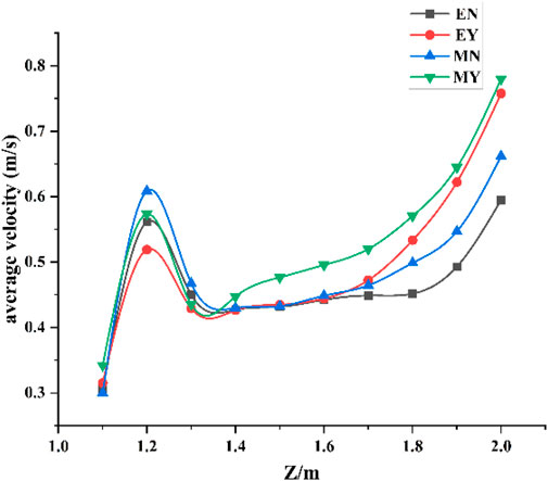
FIGURE 10. Variation curve of average phase velocity along the direction of furnace height at 3 s in four cases.
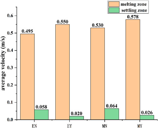
FIGURE 11. Comparison of average body velocity in melting zone and settling zone at 3 s in four cases.
Turbulent kinetic energy is common analogs of turbulent flow processes, which can characterize the intensity of turbulence. As shown in Figure 12, in the smelting zone, turbulent kinetic energy oscillates and fluctuates along the furnace length. The high-speed injection zone in the molten pool is formed around the rising path of the nozzle and the floating bubble, which is related to the distribution of the nozzle. After the high-speed jet is injected into the molten pool by the spray gun, the mixing between gas and slag increases the chaotic flow intensity in the furnace, thereby increasing the turbulent kinetic energy of the fluid. The interaction between the high-speed jet and the low-speed fluid causes the fluid on the boundary layer to be strongly sheared, resulting in many vortices. At the same time, the large-scale vortex will continue to split into small-scale vortices until it splits into the smallest-scale vortex. This transfer process promotes the heat and mass transfer and reaction process between multiphase fluids.
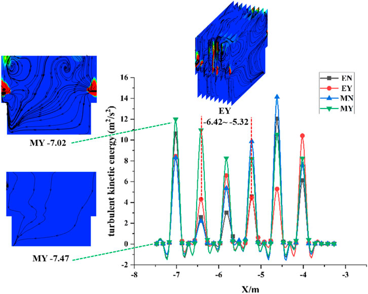
FIGURE 12. Variation curve of turbulent kinetic energy along the furnace length at 3 s under four cases.
The average turbulent kinetic energy and average turbulent dissipation rate can reflect the stirring effect in the evaluation region, as shown by the analysis results in Figure 13. Comparing the average turbulent kinetic energy in the smelting area, the case MY has a significant advantage of 2.635 m2/s2, which is increased by 47%, 34%, and 14% respectively compared with the case EN, case EY and case MN. Case MY is better enough to constrain the stirring momentum in the smelting stirring zone, so that the separation and clarification of the matte slag in the settling zone is more thorough, and the effect of the static and dynamic separation of the molten pool is realized.
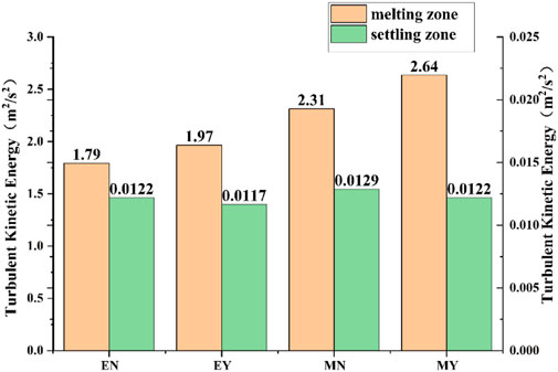
FIGURE 13. Comparison of average turbulent kinetic energy in melting zone and settling zone at 3 s in four cases.
4 Conclusion
In view of a series of problems caused by furnace type enlargement, it is creatively proposed to transform the slag chamber on one side of the furnace into the middle.
The flow field in the side blown furnace was numerically simulated, and the stirring effect in the furnace under four different working conditions was compared. The following conclusions can be drawn from this study:
1 The mechanism model of side blowing smelting system was constructed. The model is divided into seven functional layers along the furnace height in the reaction zone, which play different roles in the smelting process.
2 If there is no baffle, some oxygen-rich gas may escape to the settling area, destroy the flow field balance in the settling area, and reduce the separation efficiency of slag matte.
3 The existence of slag baffle makes the speed distribution range in the smelting mixing zone wider, the mixing range of the melt is larger, the mixing effect is better, and the role of the smelting zone is strengthened. Due to the spacing effect of the baffle, the average velocity in the settling zone of case EY is reduced to 0.02039 m/s from 0.05832 m/s of case EN, which is reduced by about 65%.
4 Case MY is sufficient to restrain the mixing momentum in the smelting mixing area from escaping to the settling area. Comparing the average turbulent kinetic energy in the smelting area, the case MY has a significant advantage of 2.635 m2/s2, which is increased by 47%, 34% and 14% respectively compared with the case EN, case EY and case MN.
Data availability statement
The raw data supporting the conclusion of this article will be made available by the authors, without undue reservation.
Author contributions
XW conducted the original manuscript writing; SW revised the manuscript; JH, HW, and QX provided the methodology; DL confirmed the manuscript.
Funding
The authors acknowledge the financial support from the National Natural Science Foundation of China (No. 52166004), the Natural Science Foundation of Yunnan Province, China (202101AU070031) and the Scientific Research Fund Project of Yunnan Education Department, China (No. 2021J0063).
Conflict of interest
Authors GD and DL were employed by the company Southwest Copper Branch of Yunnan Copper Co., Ltd.
The remaining authors declare that the research was conducted in the absence of any commercial or financial relationships that could be construed as a potential conflict of interest.
Publisher’s note
All claims expressed in this article are solely those of the authors and do not necessarily represent those of their affiliated organizations, or those of the publisher, the editors and the reviewers. Any product that may be evaluated in this article, or claim that may be made by its manufacturer, is not guaranteed or endorsed by the publisher.
References
Chen, Lin, Hao, Z., Yang, T., Liu, W., Zhang, D., Zhang, L., et al. (2015). A Comparison study of the oxygen-rich side blow furnace and the oxygen-rich bottom blow furnace for liquid high lead slag reduction. JOM 67 (5), 1123–1129. doi:10.1007/s11837-015-1375-y
Chen, P., Xiao, H., Chen, J., Chen, L., Zhang, D., Liu, W., et al. (2020). Oxygen-rich side-blown bath smelting of copper dross: A process study. J. Sustain. Metallurgy 6 (1), 344–354. doi:10.1007/s40831-020-00278-3
Cheng, W., Zhou, P., and Ji, M. A. (2014). The experimental study on the penetration behavior and bubble departure frequency of side-blowing. Beijing, China: Nonferrous Metals Engineering and Research.
Li, X., Liu, Y., Wang, D., and Zhang, T. (2020). Emulsification and flow characteristics in copper oxygen-rich side-blown bath smelting process. Metals 10 (11), 1520. doi:10.3390/met10111520
Liu, F., Peng, L. I., and Wang, H. (2017). Research on the behavior of side-blown gas jet. (Xian, China: Industrial Heating).
Liu, F., Sun, D., Zhu, R., Dong, K., and Bai, R. (2018). Effect of side-blowing arrangement on flow field and vanadium extraction rate in converter steelmaking process. Isij Int. 58 (5), 852–859. doi:10.2355/isijinternational.isijint-2017-463
Obiso, D., Akashi, M., Kriebitzsch, S., Meyer, B., Reuter, M., Eckert, S., et al. (2020). CFD modeling and experimental validation of top-submerged-lance gas injection in liquid metal. Metallurgical Mater. Trans. 51 (4), 1509–1525. doi:10.1007/s11663-020-01864-2
Obiso, D., Kriebitzsch, S., Reuter, M., and Meyer, B. (2019). The importance of viscous and interfacial forces in the hydrodynamics of the top-submerged-lance furnace[J]. Metallurgical Mater. Trans. 2019, 1–18.
Rabha, S. S., and Buwa, V. V. (2010). Volume-of-fluid (VOF) simulations of rise of single/multiple bubbles in sheared liquids. Chem. Eng. Sci. 65 (1), 527–537. doi:10.1016/j.ces.2009.06.061
Rodrigues Hendy, T., Almeida, A. R., Barrionuevo, D. C., and Fraga, R. S. (2021). Effect of the gas injection angle and configuration in the efficiency of gas lift. J. Petroleum Sci. Eng. 198, 108126. doi:10.1016/j.petrol.2020.108126
Wang, Q. M., Guo, X. Y., and Tian, Q. H. (2017). Copper smelting mechanism in oxygen bottom-blown furnace. Trans. Nonferrous Metals Soc. China 27 (4), 946–953. doi:10.1016/s1003-6326(17)60110-9
Xiao, Y., Wang, J., Lu, T., Liu, F., Lv, C., and Zhao, H. (2023). An experimental study on gas–liquid flow and mixing behavior in a copper side-blown smelting furnace. Metallurgical Mater. Trans. B 54 (2), 756–764. doi:10.1007/s11663-023-02723-6
Xiao, Y., Lu, T., Zhou, Y., Su, Q., and MuWei, L. T. (2021). Computational fluid dynamics study on enhanced circulation flow in a side-blown copper smelting furnace[J]. JOM 73 (9), 1–9.
Xiaolong, W., and Enhua, A. W. (2010). Bubble creation and multi-fluids simulation[J]. J. Computer-Aided Des. Comput. Graph. 22 (9), 1463–1467.
Yan, H. J., Xia, T., Liu, L., Zhu, Z., Zhang, L., and Huang, Q. (2014). Numerical simulation and structural optimization of gas-liquid two-phase flow in reduction furnace of lead-rich slag[J]. Chin. J. Nonferrous Metals 24 (10), 2642–2651.
Yan-ting, L. I. U., Yang, T. z., Chen, Z., Zhu, Z. y., Zhang, L., and Huang, Q. (2020). Experiment and numerical simulation of two-phase flow in oxygen enriched side-blown furnace. Trans. Nonferrous Metals Soc. China 30 (1), 249–258. doi:10.1016/s1003-6326(19)65196-4
Zhao, H., Wang, J., Zhang, W., Xie, M., Liu, F., and Cao, X. (2019). Bubble motion and interfacial phenomena during bubbles crossing liquid–liquid interfaces. Processes 7 (10), 719. doi:10.3390/pr7100719
Zhong, L. C., Wang, X., Zhu, Y. X., Chen, B. Y., Huamg, B. C., and Ke, J. X. (2010). Bath mixing behaviour in top–bottom–side blown converter. Ironmak. Steelmak. 37 (8), 578–582. doi:10.1179/030192310x12700328925741
Zhou, P., Cheng, W., and Ma, J. (2016). Experimental study on side-blown flowing characteristics. United States: Journal of Central South University.
Zhou, X., Ersson, M., Zhong, L., and Jönsson, P. G. (2015). Numerical and physical simulations of a combined top-bottom-side blown converter. Steel Res. 86 (11), 1328–1338. doi:10.1002/srin.201400376
Keywords: copper smelting, numerical simulation, side-blown, gas-slag-matte three-phase flow, velocity distribution pattern
Citation: Wu X, Wang S, Hu J, Wang H, Xiao Q, Deng G and Li D (2023) Analysis on phase distribution and flow field morphology in double side blown gas-liquid mixture flows with high temperature and high density melt. Front. Energy Res. 11:1175875. doi: 10.3389/fenrg.2023.1175875
Received: 28 February 2023; Accepted: 06 April 2023;
Published: 14 April 2023.
Edited by:
Xiaohu Yang, Xi’an Jiaotong University, ChinaCopyright © 2023 Wu, Wang, Hu, Wang, Xiao, Deng and Li. This is an open-access article distributed under the terms of the Creative Commons Attribution License (CC BY). The use, distribution or reproduction in other forums is permitted, provided the original author(s) and the copyright owner(s) are credited and that the original publication in this journal is cited, in accordance with accepted academic practice. No use, distribution or reproduction is permitted which does not comply with these terms.
*Correspondence: Shibo Wang, cGguZC53YW5nc2hpYm9AZm94bWFpbC5jb20=