 Sue Wang
 Junbo Yang
- School of Electrical and Control Engineering, Shaanxi University of Science and Technology, Xi’an, China
Under non-ideal grid operating conditions such as unbalanced grid voltage and harmonic grid that are commonly found in microgrid conditions, the negative sequence components of the microgrid voltage interfere with the active and reactive current controls in the power conversion system, leading to an increase in the harmonic content of the grid-side current and affecting the power quality of the microgrid system. To solve these problems, firstly, the mathematical model of the LCL-type power conversion system is analyzed, and a linear active disturbance rejection control based on model compensation is designed. Secondly, the influence of non-ideal power grid conditions on the control of the LCL-type power conversion system is analyzed, and the active disturbance rejection control strategy of the LCL-type power conversion system based on frequency-locked loops with harmonic cancellation modules (HCM-FLL) is proposed, which speeds up the system, improves the system’s robustness, and reduces the harmonic content of the network measurement current under the condition of power grid voltage unbalance and harmonic power grid. Finally, by using the verification of MATLAB/Simulink simulation, the current power quality obviously under the condition of voltage unbalance and harmonic power grid is evidently improved by the proposed control strategy. When compared to the traditional control methods, the control strategy proposed in this study features a simple control structure, making it easy to implement in engineering without requiring high controller performance or additional circuits. This reduces design costs and provides a wide range of controller parameters, ensuring strong anti-interference performance without the need for frequent controller parameter adjustments.
1 Introduction
The microgrid system realizes the efficient utilization and flexible control of distributed energy resources. As an important subsystem of the microgrid system, the energy storage system provides continuous and reliable power supply for the load in the microgrid system and ensures good power quality (Che et al., 2015; Xin et al., 2015; Wu et al., 2019). The LCL-type power conversion system (LCL-type PCS) is becoming more and more popular in the construction of the microgrid due to its effective filtering and small size.
Under ideal grid conditions, the control of the LCL-type PCS is relatively mature, and the output power quality can be significantly improved by adjusting the PI parameters (Gao et al., 2021) or improving the current controller (Errouissi and Al-Durra, 2018) by reasonable methods. However, in the actual operation, the microgrid often has non-ideal phenomena such as grid voltage unbalance and harmonic pollution. If the traditional vector control is adopted, the PCS output current will have serious unbalance and harmonic distortion, while the output active power and reactive power will also fluctuate, which will further pollute the microgrid and reduce the reliability of the operation of the microgrid system. Therefore, it is necessary to study the high-performance control strategy of the PCS under non-ideal power grids.
Li et al. (2021) adopted the traditional PI controller, using the positive- and negative-sequence rotating coordinate system (frame) and multiple filters to separate the positive and negative components for separate control, so as to suppress the influence of the non-ideal power grid on the inverter. The method is easy to implement, a mature technology that is widely used in engineering, but its control structure is complex, the amount of calculation is large, and it is easy to cause deterioration of the dynamic performance of the system. Jin et al. (2016)studied the model predictive control strategy of a three-phase three-level neutral point clamped (NPC) grid-connected inverter under unbalanced power grid, which improves the dynamic performance of the system. Li Z. et al. (2020) proposed a deadbeat predictive power control (DPPC) based on fuzzy PI composite controller and power prediction corrector, which realizes the stable control of a PWM rectifier under grid unbalance. The scheme proposed in Jin et al. (2016) and Li Z. et al. (2020) can achieve better control effects under the non-ideal power grid, but the controller designed by these two methods has a large amount of computation during the operation, which requires high hardware computing power that increases the system design cost. Xiong et al. (2021) proposed a strategy based on the frequency trajectory planning to improve the frequency stability of the inverter droop control in non-ideal power grids, but it is less robust to voltage–amplitude transformation and harmonic distortion. Ma et al. (2020) proposed an LCL-type grid-connected inverter control scheme based on the active disturbance rejection control and proposed a system parameter design method based on root locus analysis, which improves the stability of the grid-connected inverter under high-inductive anti-grid conditions but lacks the analysis of voltage unbalance and harmonic distortion. Li S. et al. (2020) proposed a linear/non-linear active disturbance rejection switching control phase lock loop and its pre-synchronous control strategy for virtual synchronous generator grid-connected control technology, which achieves good grid-connected effects under non-ideal conditions such as grid unbalance and frequency and phase transition, but the control structure is complex, the setting parameters are large, and the engineering implementation is difficult.
In addition, under non-ideal power grids, if the phase-locked loop cannot eliminate the harmonic interference of the power grid, it will cause the PCS to run out of sync, and in severe cases, it will even lead to system shock instability. Therefore, the influence of non-ideal power grids on phase-locked loops have to be considered simultaneously when designing control strategies. Pan et al. (2019) proposed a new type of phase-locked loop, which improves an improved-dual adaptive notch filter (IDANF) and multivariable filter (MVF), which can well eliminate the negative sequence components and fundamental frequency oscillations in non-ideal power grids, but the proposed phase-locked loop structure is complex and difficult to design. Shi et al. (2021) proposed a fixed-length transfer delay-based adaptive frequency-locked loop (TD-AFLL) to improve the detection accuracy of phase angle and amplitude under power grid distortion, but the phase-locked loop is computationally intensive and requires high hardware computing power. Din et al. (2020) described an improved phase-locked loop structure that ensures high phase margin and reduces the likelihood of resonant frequency in DFIG systems under weak grids. However, the phase-locked loop of this structure is less resistant to grid voltage unbalance and harmonic distortion. Liu et al. (2022b) improved the conventional synchronous reference frame (SRF)-PLL, which solves the problem of the large attenuation of DC components introduced by loads and grid disturbances in high-inductance and high-voltage transmission systems that causes the performance of PLL to degrade during transients but lacks the analysis of grid disturbances during steady-state periods. Liu et al. (2022a) proposed a robust real-time algorithm that can quickly separate the positive sequence component (PSC) from multiple decaying DC (DDC) components, DC bias component, negative-sequence component, and harmonics. This approach ensures a unit grid cycle response time while suppressing many types of interference. However, the disadvantage is that the algorithm has a complex structure and is difficult to design and set parameters.
Although there are many studies on PCS control strategies under non-ideal power grids, most of the control strategies are still very difficult in engineering applications because there are many interference factors in non-ideal power grids, and most of the related research can only propose solutions for some of them, and often the control structure is complex, the calculation amount is redundant, and the controller performance requirements are high. In order to overcome the above technical challenges, this article analyzes the influence of positive- and negative-sequence components of grid voltage on PCS current control under non-ideal grid conditions by establishing a three-phase LCL-type PCS mathematical model, a control strategy based on improved linear active disturbance rejection control (LADRC), and frequency-locked loop with harmonic cancellation module (HCM-FLL). When compared with the conventional control strategies, the control strategy proposed in this paper has the following advantages:
(1) The proposed control strategy combines the characteristics of LADRC with simple structure, easy implementation, and strong applicability. LADRC is introduced to improve the PCS current controller, and the active and reactive currents of the PCS are effectively controlled by using the LADRC immunity compensation idea to improve the immunity performance of the controller and enhance the robustness of the system.
(2) HCM-FLL eliminates low-frequency harmonics in harmonic grids through the pre-harmonic cancellation module and improves the frequency and phase information acquisition accuracy in harmonic power grids. At the same time, the positive- and negative-sequence calculator is used to eliminate the interaction of positive and negative components in the unbalanced power grid by controlling the positive- and negative-sequence components, respectively, and then eliminating the influence of the coupling of positive- and negative-sequence components on the output power.
2 Mathematical model of power conversion system for microgrid
The topological structure of the LCL-type PCS studied in this article is shown in Figure 1. The LCL-type PCS adopts a unipolar transformation topology.
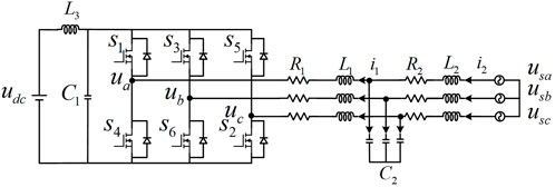
FIGURE 1. LCL-type PCS topology.
The inductance currents
where
It can be seen from Eq. 1 that the LCL-type PCS is a high-order, non-linear, strongly coupled, multivariable system with resonance characteristics. The quality of the incoming current will be affected if the controller is not decoupled and the resonance suppression strategy is not adopted properly. At present, the common decoupling and resonance suppression strategies have to obtain more parameters in the system. In practical engineering, multiple sensors are required to obtain the values of each variable, which increases the design cost. Meanwhile, affected by temperature, humidity, and service time, the PCS parameters change, thus affecting the actual control effect.
In an ideal power grid, reasonable designing of decoupling and resonance suppression strategies can control the LCL-type PCS well. In a non-ideal power grid, the positive- and negative-sequence components of the power grid will cause output power fluctuation and affect the PCS control effect.
When the three-phase power grid voltage is unbalanced according to the symmetric component method (Shigenobu et al., 2020), power grid voltage can be expressed as
where
Using voltage and current components in the
where
where
In view of the above problems, the LCL-type PCS requires a control strategy with decoupling and damping effects that is easy to be applied in engineering in a non-ideal power grid environment.
3 LCL-type PCS control strategy under non-ideal power grid condition
In view of the problems of the LCL-type PCS proposed in Section 1 under the condition of power grid voltage unbalance, an active disturbance rejection control strategy based on an improved DSOGI-FLL was proposed, as shown in Figure 2. In this article, the DSOGI-FLL with harmonic elimination function is proposed to accurately obtain the grid voltage phase under non-ideal conditions, and the current component in the coordinate system is obtained through coordinate transformation. The given current and sampled current are passed through a third-order LADRC current controller, which is then added to the voltage component. After the coordinate transformation, a drive signal is obtained through SPWM modulation to control the action of the power switching device and realize system control.
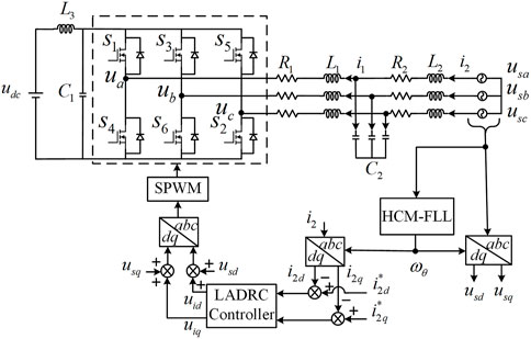
FIGURE 2. LCL-type PCS control block diagram under unbalanced grid voltage conditions.
3.1 Current controller based on third-order LADRC
The basic idea of active disturbance rejection control (ADRC) is to compensate the non-linear uncertain objects with unknown interference into integrator series-type through non-linear state feedback and combine the control rate into the ideal controller through non-linear state feedback (Chang et al., 2014). Since an extended state variable is designed by using an extended state observer to track the un-modeled and inaccurate parts of the model, as well as the disturbance and coupling parts of the model caused by external environment changes, and observe and compensate them in real time, the ADRC has the characteristics of strong robustness and anti-interference ability. However, the traditional ADRC has many parameters to adjust, and the non-linear function is difficult to determine and popularize. In order to simplify parameter settings for engineering applications, Gao (2006) proposed the linear active disturbance rejection control (LADRC), which greatly reduces the parameters that have to be adjusted and promotes the development and application of the active disturbance rejection control.
The LCL-type PCS is a high-order, non-linear, strongly coupled multivariable system with resonance characteristics. There are three coupling channels between the active current control axis and reactive current control axis in the
The order of LADRC can be judged by the number of integrators that pass through the “shortest” path from input to output of the system block diagram of the controlled object (Han, 2007). The order of the LCL-type PCS is 3, therefore it is necessary to design a third-order LADRC controller. The LADRC control structure diagram of the LCL-type PCS is shown in Figure 3.
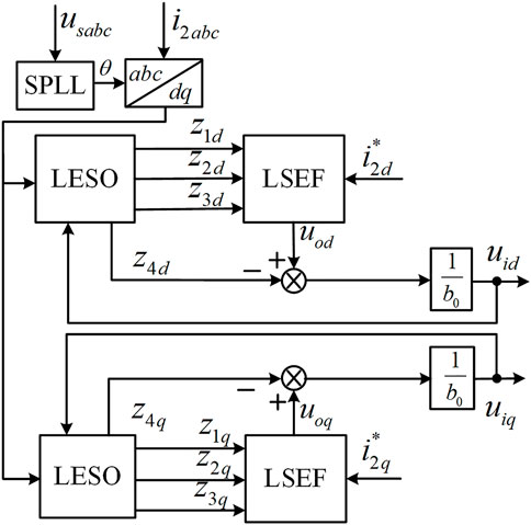
FIGURE 3. Block diagram of third-order LADRC control structure.
In Figure 3, the definition of the main circuit variable is the same as that provided in Figure 1. The fundamental wave angular frequency
The dynamic characteristics of the grid current
where
LADRC mainly includes LESO and linear state error feedback (LSEF), and their design methods are explained in the following section.
3.1.1 Design of LESO
LESO in the third-order LARC belonging to the higher-order LESO, which has a significantly enhanced disturbance suppression ability in the low-frequency band and is conducive to better the tracking system state and interference. In the middle-frequency band, the peak value of the amplitude–frequency curve of the higher-order LESO increases, and the step response produces a large overshoot or even oscillation, which is not conducive to the stability of the system. As the gain of high frequency increases, the suppression ability of high-frequency noise is significantly weakened (Zhang et al., 2015). To solve this problem, a model compensation method was proposed to introduce the resonance information
The “total disturbance” represented by
The LESO design method is the same for the d-axis and q-axis current values. Taking the d-axis current value as an example, the d-axis current differential equation in Eq. 8 is written in the form of a state-space expression.
In the formula
According to the design idea of LADRC, LESO can be established as
where
To sum up, the structural block diagram of LESO is drawn as shown in Figure 4.
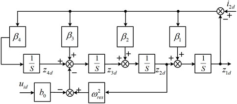
FIGURE 4. LESO structure block diagram.
The observation error of LESO can be obtained by subtracting Eq. 11 from Eq. 9, which can be written as
According to Eq. 12, the characteristic equation is
According to the modern control theory, when all characteristic roots have negative real parts, the initial bias of the observer will decay exponentially, and the decay rate depends on the position of the observer pole. The farther the imaginary axis, the faster will be the decay rate. In order to facilitate implementation, all poles of the observer are generally chosen to be the same negative real number, such that LESO converges in a finite period. Observation
According to the abovementioned ideas, all the characteristic roots of the state observer are set as
Let
Therefore,
3.1.2 Design of LSEF
For third-order LADRC, the LSEF control rate is designed as follows:
where
where
By substituting Eqs 17, 19, we then use Laplace transform to obtain the transfer function of the system on the d-axis current value as
The characteristic equation is
According to the “bandwidth method” proposed by Zhang et al.( 2015), the closed-loop pole of the system is located at
Comparing the coefficients of Eqs 20, 21, we get
During the actual designing, it is ensured that the LESO bandwidth
The design method of the q-axis LSEF is exactly the same as that of the d-axis LSEF, which is designed in the same way.
3.2 HCM-FLL structure and design
The conventional synchronous reference frame PLL (SRF-PLL) has a good response speed under the ideal grid. However, under the non-ideal grid, SRF-PLL will generate large errors in determining the grid voltage frequency and phase information due to harmonics, voltage dips, frequency variations, etc., which will cause errors in synchronizing the converter with the grid and affect the quality of the grid-connected current.
In order to solve this problem, a harmonic cancellation frequency-locked loop is proposed, which is composed of the harmonic cancellation module (HCM), second-order generalized integrator decoupling module (DSOGI-PNSC), and frequency-locked loop and phase-locked loop (FLL + PLL), as shown in Figure 5.
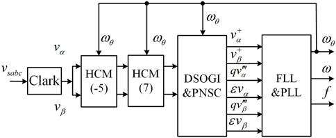
FIGURE 5. Frequency locking ring of the second-order generalized integrator with harmonic elimination function.
The advantages of this structure are as follows:
(1) The front harmonic elimination module can effectively eliminate low-frequency harmonics in the harmonic grid and improve the accuracy of frequency and phase information acquisition in the harmonic grid.
(2) DSOGI-PNSC adopts the second-order generalized integrator quadrature signal generator (SOGI-QSG), and the positive- and negative-sequence fundamental frequency components of the power grid voltage are extracted when the power grid is disturbed and the power grid voltage is unbalanced. The positive-/negative-sequence calculator (PNSC) is used to eliminate the interaction between the positive- and negative-sequence components of the voltage, to achieve the separation of positive- and negative-sequence components, by controlling the positive- and negative-sequence components, respectively, and to eliminate the influence of positive- and negative-sequence component coupling on the output power.
(3) The frequency of the adaptive filter in SOGI-QSG is provided by FLL, which depends on frequency feedback and can realize frequency adaptation of the input signal. When compared with PLL, FLL has a better stability than does PLL because the frequency information is more stable than the phase information, and the frequency oscillation is smaller and the smoothness is higher in the dynamic process.
3.2.1 SOGI-QSG module
When the power grid voltage is unbalanced, it is necessary to separate the positive- and negative-sequence components and phase lock the positive-sequence component. The orthogonal signal generator (SOGI-QSG) based on the second-order generalized integrator is shown in Figure 6. By constructing an adaptive filter based on the principle of the internal mode, it can generate signals with a difference of 90° from the input signal to achieve positive and negative sequence separation.
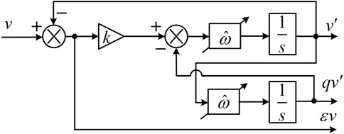
FIGURE 6. SOGI-QSG module.
In Figure 6,
Xu et al. (2021) reported that the second-order generalized integrator has band-pass filter characteristics. The smaller the
3.2.2 Harmonic cancellation module
Considering the power grid voltage unbalance containing the Nth harmonics, the power grid voltage after the Clarke transformation can be expressed as
where
When the resonant frequency of SOGI-QSG is equal to the grid voltage frequency, i.e.,
where
Eqs 25, 26 show that although both the amplitude and phase of the harmonic components change, the amplitude of the harmonics only changes with the number of harmonics. From the two equations, the Nth harmonic term
In the formula
it can be seen that the two-phase voltage obtained after the transformation eliminates the Nth harmonic component. The harmonic cancellation module (HCM) is shown in Figure 7.

FIGURE 7. Harmonic cancellation module.
3.2.3 DSOGI-FLL module
The structure of DSOGI-FLL module is composed of SOGI-QSG, positive-/negative-sequence calculator (PNSC), SOGI-FLL, and SRF-PLL. The quadrature output characteristic of SOGI-QSG can be used to achieve orthogonal phase separation of the input grid voltage signals, and then the positive- and negative-sequence components of the grid voltage in the two-phase stationary coordinate system can be calculated by PNSC, as shown in Figure 8.
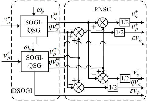
FIGURE 8. DSOGI-FLL module.
The SOGI-QSG resonant frequency

FIGURE 9. FLL + PLL module.
4 Simulation and verification
According to Figure 2, a three-phase LCL-type PCS simulation model using the MATLAB/Simulink was established. By analyzing the steady-state and dynamic performance of the three-phase LCL-type PCS system under the unbalanced power grid and harmonic power grid, the control performance of the proposed control strategy was verified.
The simulation parameters are set as follows: transformer-side inductor
The setting of the LADRC controller parameters are as follows: LESO bandwidth
4.1 Improved FLL performance verification
In order to verify the performance of the HCM-FLL proposed in this article, the Simulink platform is used to build a system simulation model, and the HCM-FLL and traditional DSOGI-PLL synchronization schemes are simulated and compared under the non-ideal grid, and the grid voltage frequency is set to 50 Hz.
In order to compare the phase-locking performance of HCM-FLL and traditional DSOGI-PLL under the unbalanced power grid, the grid voltage unbalance is set at 0.5°s, as shown in Figure 10A, and the phase-locking error of DSOGI-PLL and HCM-FLL is shown in Figure 10B. The comparison found that after introducing the unbalanced voltage after 0.5 s, the phase-locking errors of the two structures fluctuated to a certain extent and remained stable after several cycles. The phase-locking error of DSOGI-PLL was −0.3°, and the phase-locking error of HCM-FLL is close to 0. HCM-FLL can completely eliminate the influence of the unbalanced power grid and accurately track the phase information of the power grid under the unbalanced power grid.
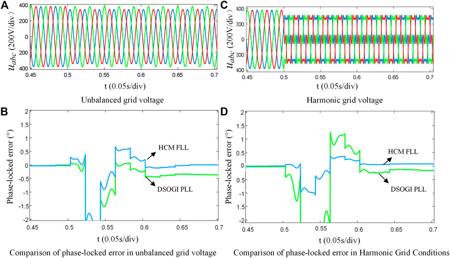
FIGURE 10. Phase-locked performance comparison.
In order to verify the performance of HCM-FLL and DSOGI-PLL under the harmonic grid, three-phase balance is maintained and 20% negative-sequence fifth harmonic and 14% positive-sequence seventh harmonic are injected into the grid at 0.5 s, as shown in Figures 10C;Figure 11D, which is a phase-locking error comparison between HCM-FLL and DSOGI-PLL under the harmonic grid. It can be seen from the figures that after adding harmonics in 0.5 s, DSOGI-PLL produces a relatively large phase-locking error, the fluctuation range is +1.5°∼ −3°, and the phase-locking error is still −0.2 after stabilization. By contrast, the fluctuation range of HCM-FLL is about −1°∼ +0.5°. After stabilization, the phase-locking error is close to 0. HCM-FLL can completely eliminate the influence of harmonics and accurately track the phase information of the grid under the harmonic grid.
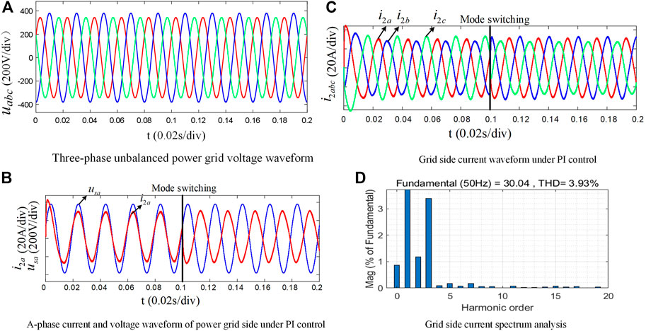
FIGURE 11. Simulation results of the traditional PI control strategy in three-phase unbalanced power grid.
4.2 Three-phase voltage unbalance in power grid
The voltage waveform of the three-phase unbalanced power grid is shown in Figure 11A. The LCL-type energy storage converter is set to work in two states: before 0.1 s, the PCS works in the grid discharge mode with 30 A power, while after 0.1 s, the PCS works in the grid charge mode with 30 A power, and the Fourier analysis is conducted on the grid current under these two operating states, respectively.
Figure 11 shows the simulation results under the traditional PI control strategy. Figure 12 shows the simulation results under the improved LADRC + HCM-FLL control strategy proposed in this article.
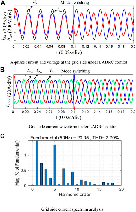
FIGURE 12. Simulation results of LADRC control in three-phase unbalanced power grid.
From Figure 11B, it can be seen that under the condition of three-phase grid unbalance, the traditional PI control strategy has the current and voltage in phase when the PCS operates in the inverter mode, with less current distortion. After 0.1 s, the PCS switches to the rectifier mode, and the current and voltage are 180° out of phase, with energy flowing from the grid side to the DC side. When compared with the inverter mode, the current waveform is significantly worse, and the third harmonic content of the grid-connected current is large, accounting for about 3.4%, and the Total harmonic distortion (THD) is 3.93%. This is because the same set of PI control parameters is used in both rectifier and inverter modes, and the PI controller is sensitive to changes in system parameters. After the system mode is switched, the control performance of the PI controller is reduced due to the changes in system parameters. From Figure 11C, it can be seen that under the condition of the three-phase grid voltage unbalance, the traditional PI control strategy outputs have unbalanced the three-phase grid-connected current with a large amplitude difference.
From Figure 12A, it can be seen that under the condition of three-phase grid voltage unbalance, the improved LADRC + HCM-FLL control strategy can maintain good current quality in both the rectifier and inverter modes, reflecting the good anti-parameter variation characteristics of the LADRC controller. Figure 12B shows that the three-phase grid-connected current output is balanced under the control of the improved strategy, and the amplitude difference is small. Figure 12C shows that when compared with the PI control strategy, the third- and fifth-harmonic content of the grid-connected current is significantly reduced, accounting for about 0.6% when the total THD is 2.7%, which is a significant improvement over the PI control.
4.3 Harmonic grid condition
In order to study the anti-disturbance performance of the LADRC + HCM-FLL control strategy under harmonic power grid conditions, assuming that the power grid voltage is balanced and frequency is unchanged, the fifth and seventh harmonic components are injected at 0.1 s corresponding to 10% and 5% of the amplitude of the power grid voltage base wave, respectively, as shown in Figure 13.
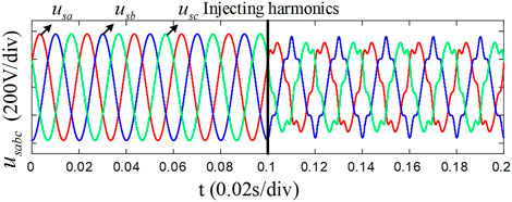
FIGURE 13. Voltage waveform of the three-phase harmonic power grid.
It can be seen from Figures 14, 15 that both PI and LADRC current control based on HCM-FLL can better control the grid-side current under the harmonic grid. When compared with the PI control strategy, LADRC current control can better suppress the fifth and seventh harmonics of the grid-side current (about 1.3% and 1% reduction, respectively), resulting in a 1.28% reduction in the total THD and achieving better quality of the incoming grid current.
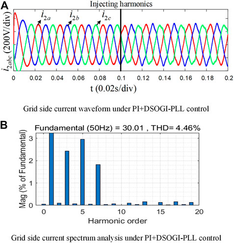
FIGURE 14. Simulation results of PI + DSOGI-PLL control in three-phase harmonic power grid.
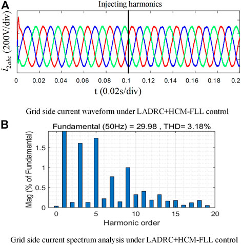
FIGURE 15. Simulation results of LADRC + HCM-FLL control in three-phase harmonic power grid.
5 Conclusion
This article aims to address the issues of grid voltage unbalance and harmonic problems that the LCL-type PCS frequently encounters in microgrid environments. To achieve this, we analyzed the mathematical model of the LCL-type PCS, designed a linear active disturbance rejection controller based on model compensation, and investigated the influence of grid voltage unbalance and harmonics on the LCL-type PCS. Furthermore, we propose an active anti-disturbance control strategy for the LCL-type PCS based on a generalized second-order integrator frequency-locked loop. According to the simulation results presented in Section 3, our proposed control strategy offers the following benefits:
(1) The HCM-FLL structure based on the specified number of harmonic elimination can effectively realize the conversion and independent control of the positive- and negative-sequence components of the power grid voltage and respond quickly and accurately to the working conditions such as power grid voltage unbalance and harmonic grid conditions that have been generated in the microgrid environment.
(2) In the traditional PI control strategy in the state of the unbalanced power grid voltage, the three-phase output of the grid-side current is unbalanced, with a large amplitude difference and high third-harmonic content. The LADRC current control strategy in this article can achieve good control of the grid-side current under the same conditions, with balanced three-phase current, small differences in amplitude, and the effective suppression of the third-harmonic content.
(3) The traditional PI control strategy in the harmonic power grid has large current distortions on the grid side, unbalanced output current, and high harmonic content. The LADRC current control strategy in this article can effectively suppress the current harmonics on the grid side under the same conditions (when compared with PI, the fifth and seventh harmonics are reduced by about 1.3% and 1%, respectively), and the total THD is reduced by 1.28%. The current quality improvement effect is obvious.
Data availability statement
The original contributions presented in the study are included in the article/Supplementary Material; further inquiries can be directed to the corresponding author.
Author contributions
JY wrote the manuscript, SW provided the conceptual idea, and JY built the simulation environment.
Conflict of interest
The authors declare that the research was conducted in the absence of any commercial or financial relationships that could be construed as a potential conflict of interest.
Publisher’s note
All claims expressed in this article are solely those of the authors and do not necessarily represent those of their affiliated organizations, or those of the publisher, editors, and reviewers. Any product that may be evaluated in this article, or claim that may be made by its manufacturer, is not guaranteed or endorsed by the publisher.
References
Chang, X., Li, Y., Zhang, W., Wang, N., and Xue, W. (2014). Active disturbance rejection control for a flywheel energy storage system. IEEE Trans. Industrial Electron. 62 (2), 991–1001. doi:10.1109/tie.2014.2336607
Che, L., Shahidehpour, M., Alabdulwahab, A., and Al-Turki, Y. (2015). Hierarchical coordination of a community microgrid with AC and DC microgrids. IEEE Trans. Smart Grid 6 (6), 3042–3051. doi:10.1109/TSG.2015.2398853
Din, Z., Zhang, J., Bassi, H., Rawa, M., and Song, Y. (2020). Impact of phase locked loop with different types and control dynamics on resonance of DFIG system. Energies 13 (5), 1039. doi:10.3390/en13051039
Errouissi, R., and Al-Durra, A. (2018). Design of PI controller together with active damping for grid-tied <italic>LCL</italic>-Filter systems using disturbance-observer-based control approach. IEEE Trans. Industry Appl. 54 (4), 3820–3831. doi:10.1109/TIA.2018.2823258
Gao, N., Lin, X., Wu, W., and Blaabjerg, F. (2021). Grid current feedback active damping control based on disturbance observer for battery energy storage power conversion system with LCL filter. Energies 14 (5), 1482. doi:10.3390/en14051482
Gao, Z., Scaling and bandwidth-parameterization based controller tuning, Proceedings of the 2003 American control conference, June 2003, 4989–4996. Denver, CO, USA.
Han, J. (2007). Active disturbance rejection control technique-the technique for estimating and compensating the uncertainties. Beijing: National Defence Industry Press. 978-7-05795-9. Arlington, Virginia.
Jin, T., Wei, H., Nzongo, D. L. M., and Zhang, Y. (2016). Model predictive control strategy for NPC grid-connected inverters in unbalanced grids. Electron. Lett. 52 (14), 1248–1250. doi:10.1049/el.2016.1285
Li, J., Zhang, Y., Zhao, Y., Ren, L., Wang, J., and Liu, Y. (2021). An improved three-stages cascading passivity-based control of grid-connected LCL converter in unbalanced weak grid condition. IEEE Access 9, 89497–89506. doi:10.1109/ACCESS.2021.3091210
Li, S., Li, Y., Chen, X., Jiang, W., Li, X., and Li, T. (2020). Control strategies of grid-connection and operation based on active disturbance rejection control for virtual synchronous generator. Int. J. Electr. Power & Energy Syst. 123, 106144. doi:10.1016/j.ijepes.2020.106144
Li, Z., Cheng, W., Xiao, Q., and Liao, W. (2020). Deadbeat predictive power control with fuzzy PI compound controller and power predictive corrector for PWM rectifier under unbalanced grid conditions. Int. J. Fuzzy Syst. 22 (4), 1277–1288. doi:10.1007/s40815-020-00847-4)
Liu, X., Wu, B., and Xiu, L. (2022). A fast positive-sequence component extraction method with multiple disturbances in unbalanced conditions. IEEE Trans. Power Electron. 37 (8), 8820–8824. doi:10.1109/TPEL.2022.3161734
Liu, X., Xiong, L., Wu, B., Qian, Y., and Liu, Y. (2022). Phase locked-loop with decaying DC transient removal for three-phase grids. Int. J. Electr. Power&Energy Syst. 143, 108508. doi:10.1016/j.ijepes.2022.108508
Ma, W., Guan, Y., Zhang, B., and Wu, L. (2020). Active disturbance rejection control based single current feedback resonance damping strategy for LCL-type grid-connected inverter. IEEE Trans. Energy Convers. 36 (1), 48–62. doi:10.1109/TEC.2020.3006151
Pan, H., Li, Z., and Wei, T. (2019). A novel phase-locked loop with improved-dual adaptive notch filter and multi-variable filter. IEEE Access 7, 176578–176586. doi:10.1109/ACCESS.2019.2958135
Shi, W., Yu, J., and Guo, Y. (2021). An enhanced adaptive frequency-locked loop based on fixed-length transfer delay. IEEE Trans. Power Syst. 37 (1), 792–795. doi:10.1109/TPWRS.2021.3095404
Shigenobu, R., Nakadomari, A., Hong, Y.-Y., Mandal, P., Takahashi, H., and Senjyu, T. (2020). Optimization of voltage unbalance compensation by smart inverter. Energies 13 (18), 4623. doi:10.3390/en13184623
Wang, Y., Li, X., and Li, Y. (2020). Power-current coordinated control without sequence extraction under unbalanced voltage conditions. IET Power Electron. 13 (11), 2274–2280. doi:10.1049/iet-pel.2019.1141
Wu, Y., Zhang, D., Xiong, L., Wang, S., Xu, Z., and Zhang, Y. (2019). Modeling and mechanism investigation of inertia and damping issues for grid-tied PV generation systems with droop control. Energies 12 (10), 1985. doi:10.3390/en12101985
Xin, H., Zhang, L., Wang, Z., Gan, D., and Wong, K. P. (2015). Control of island AC microgrids using a fully distributed approach. IEEE Trans. Smart Grid 6 (2), 943–945. doi:10.1109/TSG.2014.2378694
Xiong, L., Liu, L., Liu, X., and Liu, Y. (2021). Frequency trajectory planning based strategy for improving frequency stability of droop-controlled inverter based standalone power systems. IEEE J. Emerg. Sel. Top. Circuits Syst. 11 (1), 176–187. doi:10.1109/JETCAS.2021.3052006
Xu, J., Qian, H., Hu, Y., Bian, S., and Xie, S. (2021). Overview of SOGI-based single-phase phase-locked loops for grid synchronization under complex grid conditions. IEEE Access 9, 39275–39291. doi:10.1109/ACCESS.2021.3063774
Keywords: microgrid system, non-ideal grid, LCL-type power conversion system, LADRC, DSOGI-FLL
Citation: Wang S and Yang J (2023) Active disturbance rejection control of three-phase LCL power conversion system under non-ideal grid conditions. Front. Energy Res. 11:1170058. doi: 10.3389/fenrg.2023.1170058
Received: 20 February 2023; Accepted: 20 March 2023;
Published: 04 April 2023.
Edited by:
Liansong Xiong, Xi’an Jiaotong University, ChinaReviewed by:
Zaki Ud Din, National University of Sciences and Technology (NUST), PakistanBin Zhou, Hunan University, China
Copyright © 2023 Wang and Yang. This is an open-access article distributed under the terms of the Creative Commons Attribution License (CC BY). The use, distribution or reproduction in other forums is permitted, provided the original author(s) and the copyright owner(s) are credited and that the original publication in this journal is cited, in accordance with accepted academic practice. No use, distribution or reproduction is permitted which does not comply with these terms.
*Correspondence: Junbo Yang, MTA1Nzg2MjA2N0BxcS5jb20=