 Gabriele Benzoni
 Carolina Introini
 Stefano Lorenzi
 Lorenzo Loi
 Antonio Cammi
- Politecnico di Milano, Department of Energy, Nuclear Engineering Division, Milan, Italy
In the continuous strive to improve the safety of current-generation and next-generation nuclear power plants, natural circulation can be used to design passive safety systems to remove the decay heat during the shutdown. The Molten Salt Fast Reactor (MSFR) is a peculiar type of Gen-IV nuclear facility, where the fluid fuel is homogeneously mixed with the coolant. This design leads to natural circulation in the presence of an internally distributed heat source during the shutdown. Furthermore, to shield the environment from the highly radioactive fuel, an intermediate loop between the primary and the secondary loops, able to operate in natural circulation, is required. To analyze the natural circulation with a distributed heat source and to study the natural circulation of coupled systems and the influence of the intermediate loop on the behaviour of the primary, Politecnico di Milano designed and built the DYNASTY-eDYNASTY facility. The two facilities are coupled with a double-pipe heat exchanger, which siphons heat from DYNASTY and delivers it to the eDYNASTY loop. This work focuses on modelling the coupled DYNASTY-eDYNASTY natural circulation loops using DYMOLA2023®, an integrated development environment based on the Modelica Object-Oriented a-causal simulation language. The 1D Modelica approach allows for building highly reusable and flexible models easing the design effort on a complex system such as the DYNASTY-eDYNASTY case without the need to rewrite the whole model from scratch. The coupled models were developed starting from the already-validated single DYNASTY model and the double-pipe heat exchanger coupling. The models were tested during the whole development process, studying the influence of the numerical integration algorithm on the simulation behaviour. A preliminary analysis of both the adiabatic and the heat loss models analyzed the effect of the secondary natural circulation loop on the behaviour of the DYNASTY loop. The simulation results showed that the eDYNASTY loop dampens the behaviour of the primary DYNASTY loop. Furthermore, a parametric analysis of the DYNASTY and the eDYNASTY coolers highlighted the influence of the cooling configuration on the facility’s behaviour. Finally, the simulation results identified the most critical aspects of the models in preparation for an experimental comparison.
1 Introduction
Natural circulation is the physical phenomenon that describes the spontaneous motion of a fluid due to density gradients (Bergman et al., 2011). The exploitation of natural circulation to passively remove the decay heat during shutdown operations is of significant interest to the nuclear industry as it does not require active systems, thus increasing the overall safety of the system. It has already been adopted in the current-generation reactors, such as the AP-1000 (Sutharshan et al., 2011) and the ESBWR (Rassame et al., 2017), and it is currently a primary target of research for the development of the safety system for Gen-IV nuclear reactors, in particular for the molten salt fast reactor (MSFR) (Serp et al., 2014). Natural circulation as a passive heat removal strategy relies on the system’s ability to sustain the temperatures required to achieve the necessary mass flow rate; natural circulation arises as a result of the balance between buoyancy forces, which drive natural circulation, and the friction losses, which may hinder fluid mobility, leading to oscillatory phenomena (e.g., inversion of the fluid’s motion). These instabilities must be avoided when designing a safety system since they would compromise the system’s heat dissipation capabilities.
The MSFR is a particular type of Gen-IV reactor characterized by the presence of fuel in the fluid phase that is homogeneously mixed with a thermal carrier (Serp et al., 2014). This peculiarity entails, among other phenomena, natural circulation in the presence of a homogeneously distributed internal heat source during shutdown (Jeong et al., 2018); thus, there is a need to study the influence of internal heat generation (IHG) on natural circulation when designing a fully passive natural circulating decay heat removal system (DHRS). Furthermore, to shield the environment and the balance of plant from radioactive fuel of the MSFR, an intermediate loop, which also operates in natural circulation, must be used; the influence of this additional loop on the behaviour of natural circulation in the primary loop needs to be assessed. However, studying a configuration where there is a coupled natural circulation loop system with IHG in the primary loop is a non-trivial task as it would require either chemically reactive or nuclear fluid. As a first approximation, the influence of an internal heat source on the system can be considered similar to the effect of an externally distributed source if the axial length of the system is much greater than the radial one. In such a system, the variation of thermo-physical quantities along the radial length can be considered negligible with respect to the one along the axial length so that the fluid can be considered mono-dimensional and IHG can be approximated with an external heat source (EHS) (Cammi et al., 2016a; Cammi et al., 2016b).
Natural circulation loops (NCLs) are facilities that have an axial length greater than the radial one (Misale and Garibaldi, 2010; Pini, 2017; Cauzzi, 2019), providing important tools for studying the influence of a distributed heat source on the behaviour of natural circulation. In single-phase NCLs, such as the Bhabha single-phase natural circulation loop (Vijayan, 2002), the L2 loop (Misale and Garibaldi, 2010), and the coupled natural circulation loop (CNCL) (Elton et al., 2022), the flow behaviour is mainly affected by density wave instabilities (Welander, 1967). The characteristic velocity of such phenomena significantly depends on local properties such as temperature and pressure losses. Welander (1967) investigated the problem of natural circulation loop instability by proposing a model based on the growth of small oscillations due to the formation of hot and cold wave packets inside the system. The amplification of hot wave packets that pass through a heat source contributes positively to the buoyancy flow, allowing the mass flow rate reach its maximum. Instead, when the hot wave packets pass through the heat sink, the buoyancy flow receives a negative contribution that causes the mass flow rate to decrease to its minimum value. This decrease then enables the formation of a new hot packet in the heat source. The same reasoning applies to the cold wave packet, and the fluid behaves like a pendulum (Welander, 1967). One of the possible outcomes of the pendulum-like behaviour is an oscillating flow, where the balance between the energy supplied to the system and the energy dissipated is not reached. In such cases, the maximum value of the mass flow rate corresponds with the maximum value of the energy dissipated, which then decreases the value of the mass flow rate to its minimum. The minimum value of the mass flow rate also corresponds to the minimum value in the energy dissipated, leading to a build-up in potential energy, which increases the mass flow rate. This unstable behaviour can be bounded, where the oscillations are not dampened, or transient, where the oscillations are dampened, leading to a stationary steady-state outcome (Ruiz et al., 2015).
The problem of natural circulation stability is a well-known and studied issue (Welander, 1967; Vijayan, 2002; Schmid and Brandt, 2014; Cammi et al., 2016b; Battistini et al., 2021). In natural circulation, the driving force is due to density gradients in the fluid which in turn are due to temperature differences. On the other hand, the friction force hinders the fluid’s motion (Bergman et al., 2011). One of the main issues in studying this phenomenon is that the magnitude of the friction forces depends on the mass flow rate of the fluid, which is related to density gradients. These two competing forces significantly depend on fluid thermal properties which, for a system at constant pressure, are solely related to fluid temperature distribution. Furthermore, the addition of a secondary natural circulation loop further influences the stability of the primary loop, which also significantly depends on the heating configuration and initial conditions (Elton et al., 2022).
To study the effect of a distributed heat source on the behaviour and stability of natural circulation, and the influence of a secondary loop in this behaviour, the DYNASTY–eDYNASTY facility (dynamics of natural circulation for molten salt internally heated) has been designed and built at Politecnico di Milano (Pini, 2017; Cauzzi, 2019). A picture of the coupled facility is shown in Figure 1. The coupling of the facilities is realised with a double-pipe heat exchanger placed on DYNASTY’s right vertical leg. The heat exchanger behaves as an additional heat sink to the finned cooler for the DYNASTY facility during operation, while it behaves as the main heat source for the eDYNASTY facility. Thus, while DYNASTY can operate in three different heating configurations [horizontal heater horizontal cooler (HHHC), vertical heater horizontal cooler (VHHC), and distributed heating (DH)], eDYNASTY only operates in the VHHC configuration. The study of natural circulation on the single DYNASTY loop has already been tackled numerically with a 1D approach (Pini, 2017; Cauzzi, 2019; Benzoni et al., 2023) and a 3D one (Pini, 2017; Cauzzi, 2019; Battistini et al., 2021; Nalbandyan et al., 2022). The analysis of the DYNASTY facility has also been performed experimentally (Cauzzi, 2019; Benzoni et al., 2022a). However, the study of the coupled DYNASTY–eDYNASTY loops was limited to a 1D preliminary analysis (Benzoni et al., 2022b). This paper focuses on the 1D Modelica modelling of the coupled DYNASTY–eDYNASTY natural circulation facility using Dymola 2023®, an integrated development environment (IDE) based on the Modelica object-oriented (O-O) simulation language, as it provides robust integration algorithms that are able to simulate the complexities of the system (Dassault Systèmes, 2023). The models developed are based on the ones used for the uncoupled DYNASTY facility developed in previous works (Pini, 2017; Cauzzi, 2019; Benzoni et al., 2023), which uses the ThermoPower library as a foundation (Casella and Leva, 2003; Casella and Leva, 2005). The high reusability and adaptability of the Modelica approach allow for fast development and simulation of different models without the need to rewrite the whole system from scratch (Fritzson, 2014). The scope of this work is to provide a detailed analysis of the coupled DYNASTY–eDYNASTY facility Modelica models, using different heating configurations and probing the influence of the additional secondary loop on the behaviour of the primary one. In particular, this work focuses on analysing the impact of the secondary loop heat sink on the coupled facility models.
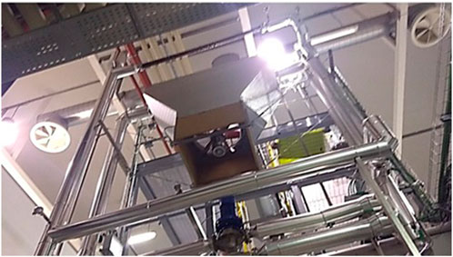
FIGURE 1. Picture of the coupled DYNASTY–eDYNASTY natural circulation loops as built.
This paper is structured as follows: in Section 2, the coupled DYNASTY–eDYNASTY facility is presented in detail showing the coupling and the different regions of the facility; in Section 3, the 1D Modelica modelling of the coupled natural circulation loop is presented, analysing the behaviour of the different numerical integration algorithms on the simulations. In Section 4, the simulation outcomes are presented and discussed for the developed models, focussing on the influence of the eDYNASTY loop on the behaviour of the DYNASTY loop. Finally, in Section 5, the main outcomes of this work will be presented along with future activities.
2 Coupled DYNASTY–eDYNASTY facility
The coupled DYNASTY–eDYNASTY experimental facility is made of two square rectangular loops realised in stainless steel. In particular, the DYNASTY loop is made of AISI 316L, while the eDYNASTY loop is made of AISI 304. Both facilities are designed and built at Politecnico di Milano (Pini, 2017; Cauzzi, 2019; Benzoni et al., 2023). Their scope is to study the dynamics and stability of different fluids under natural circulation, with a distributed heat source, when influenced by the thermal inertia caused by a secondary natural circulation loop. In the DYNASTY loop, all legs have approximately the same length, while in the eDYNASTY loop the vertical legs are slightly longer than the horizontal ones by approximately 100 mm. Figure 2 shows a detailed schematic view of the coupled facility main sections. Figure 2A shows a detailed schematic view of the DYNASTY facility, whereas Figure 2B shows a detailed schematic view of the eDYNASTY facility; all the lengths reported have a tolerance of 10 mm. Both facilities have an internal pipe diameter of 38 mm with a 2 mm wall thickness.
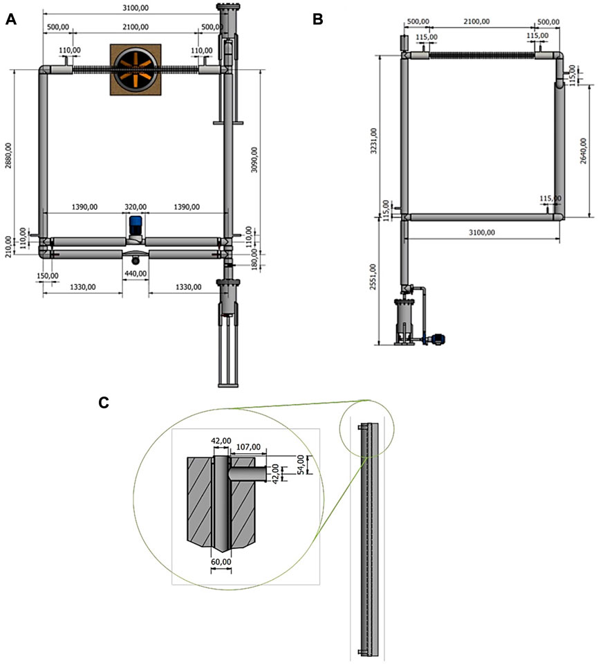
FIGURE 2. (A) DYNASTY geometrical view, (B) eDYNASTY geometrical view, and (C) DYNASTY–eDYNASTY heat exchanger coupling.
To perform the experiments, the working fluid is loaded in DYNASTY and eDYNASTY by using two different filling systems. DYNASTY uses an upper loading tank, while eDYNASTY is loaded from the bottom by using a pump. The different working fluid combinations foreseen in the coupled DYNASTY–eDYNASTY loop are water–water, glycol–water, and glycol–glycol [TYFOCOR LS® TYFOPROP (2020)]. The DYNASTY–eDYNASTY facility currently operates only with single-phase fluids.
The coupled facility is highly flexible, allowing the adoption of different heating configurations (VHHC, HHHC, and DH) achieved by powering different sections of the plant (heater legs). Heating is provided using heating strips, with three strips housed in the vertical legs and two in the horizontal one. In the coupled configuration, the right DYNASTY leg (GV2) is bypassed by the heat exchanger, limiting the total amount of heat that can be supplied to the DH configuration. The coupling between the DYNASTY and eDYNASTY facilities is realised with a double-pipe heat exchanger (HX), as shown in Figure 2C; the DYNASTY side is the internal pipe of the HX, while the annulus pipe is the eDYNASTY side. The different heating configuration maximum power values for the coupled configuration are the following: 0 W to GV2, 2,068 W to GV1, 1,369 W to GO1, and 3,437 W for the DH configuration (total power).
The coupled facilities cooling system is realised by two finned pipes in a cross flow, one for each NCL. Both coolers are coupled with a fan that supplies the desired airflow rate. To independently test the influence of the heat sink position, a deflector has been installed to stop the air supplied to either DYNASTY or eDYNASTY. The maximum airflow rate achievable by the fan is 4 m3s−1 for both NCLs, while the fan surface area is 1.4 m2.
The main measuring system of the coupled facility is composed of four ELSI® Type J class 1 thermocouples measuring the DYNASTY fluid temperature (ELSI, 1998), five ELSI® Type J class 1 thermocouples measuring the eDYNASTY fluid temperature (ELSI, 1998), and one Endress-Hauser® Promass F80 DN25 Coriolis mass flow rate metre which measures the DYNASTY mass flow rate (Endress-Hauser, 2016). The DYNASTY temperature sensors are arranged to return temperature gradient data for each section, where heat is either provided (heater legs) or removed (HX, cooler). In the eDYNASTY loop, the fluid thermocouples are arranged similar to the DYNASTY one, with the only difference being the addition of a fifth thermocouple TS5 between the cooler and the HX (as shown in Figure 3B). Figure 3 shows a schematic view of both loops illustrating the sensors’ placements, the different plant section names, and the heated areas for the DYNASTY facility in red. In Figure 3A, the right DYNASTY leg (GV2) is coloured in blue to differentiate it from other heater elements (GV1 and GO1). In the coupled configuration, the GV2 leg is bypassed and no power is delivered.
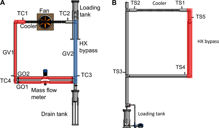
FIGURE 3. (A) DYNASTY and (B) eDYNASTY schematic views identifying the different sections of the plant.
3 Coupled facility 1D Modelica modelling
This work presents the first step in the 1D modelling of the coupled DYNASTY–eDYNASTY. The modelling approach to the coupled DYNASTY–eDYNASTY facility follows the same approach used for the single DYNASTY loop (Pini, 2017; Cauzzi, 2019). The phenomenon of natural circulation is then modelled using the Boussinesq approximation to calculate the density gradients in the loop, which then induces a spontaneous flow. Furthermore, the mass flow rate and the flow regime are assumed to be the same in the entire loop. At the same time, the fluid is considered incompressible with a mono-directional flow in the axial direction (Cammi et al., 2016a; Cammi et al., 2016b). The developed DYNASTY–eDYNASTY models follow the schematics that are shown in Figure 4, where the DYNASTY loop is represented by the components to the left of the HX and the eDYNASTY loop is on the right of the HX component. These preliminary 1D models account for a simplified geometry to improve simulation stability; the HX length is assumed to be the whole vertical leg, while the cooler is assumed to have the same length as the horizontal leg GO1.
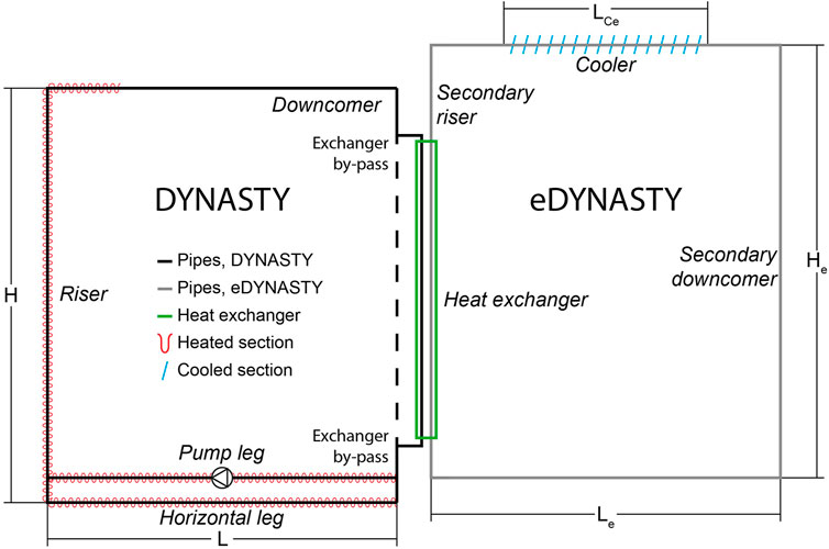
FIGURE 4. Schematic view of the coupled DYNASTY–eDYNASTY loop when using the eDYNASTY cooler.
In this work, the models are developed starting with a preliminary adiabatic condition to test the components, in particular, the HX coupling. Then, the models were expanded with both heat losses from the environment and the finned cooler. Due to its speed of simulation and its easiness of models customisation, the framework adopted is the Dymola 2023® IDE, a simulation environment based on the Modelica simulation language (Dassault Systèmes, 2023). Modelica is an acausal and object-oriented simulation language that describes physical systems using physical and engineering principles, such as mass and energy balances (Fritzson, 2014). Modelica describes the physical phenomena of the system using equations instead of assignments, without the need to define input–output relations. Furthermore, the different components, also called classes, are defined independently from their potential connections, allowing the development of so-called “super-classes” which are generalized versions of the model components that are then specialized to build the considered system. The instantiated classes, which constitute the single components of the system, are then linked with connections to build the final model. The connections, when made, automatically implement energy, mass, and momentum balance relations between the different interfaces of the components, enabling a more flexible and efficient data flow Fritzson (2014). However, the cost is that a differential-algebraic equation (DAE) system has to be solved and that numerical solvers are inherently casual. To solve the DAE system, an additional step is required, where the simulation engine translates the system of equations into a stiff ordinary differential equation system (Fritzson, 2014; Cellier and Kofman, 2006) before solving the problem (Pantelides, 1988). The Pantelides algorithm changes the system of equations by differentiating them until the obtained order of the DAE system, defined as the minimal number of differentiation needed to solve the system in his variables and in time, is lower or equal to 1. To solve the translated ODE system, Dymola 2023® offers different numerical integration algorithms, ranging from linear multi-step methods to single-step ones (Dassault Systèmes, 2023). The Dymola 2023® development environment allows the development of Modelica models with a detailed graphical user interface. In particular, the graphical interface allows the placement of the model’s components and links them together. The textual interface is instead used to write the equations that models the component. Furthermore, the Dymola 2023® IDE is also able to simulate the developed Modelica models with the simulation interface.
Compared to the single DYNASTY facility, the modelling of the coupled facility requires the introduction of the double-pipe HX model, which adds an additional degree of complexity. In particular, the HX model needs to be able to operate in natural circulation on both the annulus and the internal sides, without a prior definition of its regime (either a parallel flow or a counter-current one). Therefore, the first step in modelling the coupled loops facility was the development of the HX model. Figure 5 shows the coupled facility HX models developed in this work; Figure 5A is the adiabatic HX model, while Figure 5B is the more advanced HX model with the addition of the heat losses. The HX has been built using two “customflow1DFEM” components and one “metalTubeFEM” component, two specialized classes housed in the ThermoPowerIHG library (Pini, 2017; Cauzzi, 2019). The preliminary developed HX model is shown in Figure 5A. In the HX model, the two pipe components “internalPipe” and “Annulus,” which, respectively, are the DYNASTY and the eDYNASTY pipe sections, are linked to external interfaces to put the model in communication with the rest of the loop. The component ‘metalTubeFEM’ links the two pipe sections of the HX, accounting for the heat exchange between the annulus, inner fluid, and pipe wall. In the HX model, the heat transfer between the fluid and the pipe walls is calculated with the correlation developed by Pini (2017) and Cauzzi (2019), which uses logistic functions to develop a continuous correlation to calculate the Nusselt number. Then, heat flows through the “metalTubeFEM,” and this component acts as the cylindrical metal wall between the two annuli and the internal pipe regions of the HX. In the component, heat is transferred between the two walls using the heat conduction equation (Casella and Leva, 2003; Casella and Leva, 2005). Finally, heat is transferred in the eDYNASTY loop fluid (which flows in the annulus section) by using the same continuous heat transfer correlation that was used for the internal pipe. This HX model does not exchange heat with the environment and can also be used to account for eventual IHG on the DYNASTY side (the internal pipe is linked with the IHG source “IHG1DFEM”). The preliminary developed coupled facility models involved only the coupling of the HX with the three DYNASTY legs (GO1, GV1, and the cooler), with a fixed mass flow rate to test if the developed HX model was able to complete the simulations. Thus, the HX was tested with natural circulation on both sides before modelling the whole preliminary DYNASTY–eDYNASTY loop, with fully adiabatic pipes and temperature-imposed coolers.
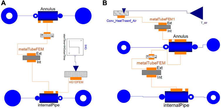
FIGURE 5. (A) HX preliminary adiabatic model and (B) HX model with heat losses inclusion.
The next addition to the coupled facility HX modelling is the heat loss model. The addition of the heat loss model allows for testing their influence on the simulations and to compare the simulation results to the current configuration of the experimental facility, as in Benzoni et al. (2023). To introduce the heat losses in the coupled facility model, the HX was adapted with the inclusion of an additional metal wall component “metalTubeFEM” representing the outer wall of the HX. This model is then connected with the “Annulus” pipe to account for the conduction between the eDYNASTY fluid and the HX metal wall. Finally, the metal wall component is linked with an external heat source, which accounts for the heat transfer with the environment. In this model, the IHG port of the internal pipe was suppressed, limiting it to only EHS. However, the IHG port can easily be turned on when simulating IHG transients. The HX model is shown in Figure 5B. In the model, the “metalTubeFEM” component accounts for the heat transfer through the wall between the annulus and the internal pipe, while the component “metalTubeFEM1” accounts for the heat transfer between the annulus pipe wall and the environment. To account for the HX heat exchange with the air, the “metalTubeFEM1” component is linked with the “Conv_HeatTransf_Air” component that calculates the air Nusselt number, according to the Churchill–Chu correlations, for smooth pipes in the cross flow (Bergman et al., 2011). The component which models the heat transfer between the pipe surface and the environment “Conv_HeatTransf_Air” is also used to account for the heat loss in heater pipes and in the non-heated section of the mass flow rate metre.
The Coupled DYNASTY–eDYNASTY models developed are shown in Figure 6. The preliminary adiabatic model, shown in Figure 6A, was developed similar to the DYNASTY one (Pini, 2017; Cauzzi, 2019; Benzoni et al., 2023), with one “parameter” block and a “system” one. These blocks housed all the different simulation parameters and initialisation conditions. The different heating configurations of the DYNASTY facility are achieved by the “powerdivider” block following the “extPower” block, which supplies the external power signal. The block “intPower” is used to account for internal heat generation that is not considered in this work. The “powerdivider” allows tuning the power fraction that each leg receives. Due to the presence of the unheated HX (the HE component in the model), the power signal is only delivered to “L7” (the GV1 leg in the DYNASTY facility) and to the two horizontal pipes “L3” and “L4” (the GO1 leg in the DYNASTY facility). Being the same as those used for the DYNASTY loop section, the components on the eDYNASTY side also require power signals; however, since only the DYNASTY loop delivers heating, the power signal for these components is set to zero. In the loop, the temperature sensors are named either “DYN_TC(i)” or “eDYN_TC(i),” where (i) corresponds to the sensor number. The mass flow rate measurement points are housed in the horizontal leg of DYNASTY and of eDYNASTY and are named “DYNsensW” or “eDYNsensW,” respectively. To account for the localized pressure drops of the plant elbows and of the DYNASTY mass flow rate metre (Endress-Hauser, 2016), the “pressDrop” components were included in the coupled facility models (Cauzzi, 2019; Benzoni et al., 2023). All the components used, except for the power dividers and the DYNASTY–eDYNASTY pipes, are standardized components available in the ThermoPower library (Casella and Leva, 2003; Casella and Leva, 2005). This model (Figure 6A) provides the general structure of the facility. This model lacks the presence of the “sinkPressure” on the eDYNASTY part of the loop, as this model was only used to test HX coupling and the general structure of the coupled facility. The component “sinkPressure” was then added on the eDYNASTY side of the models to correctly account for the real facility expansion tank, which must be considered before experimental comparison.
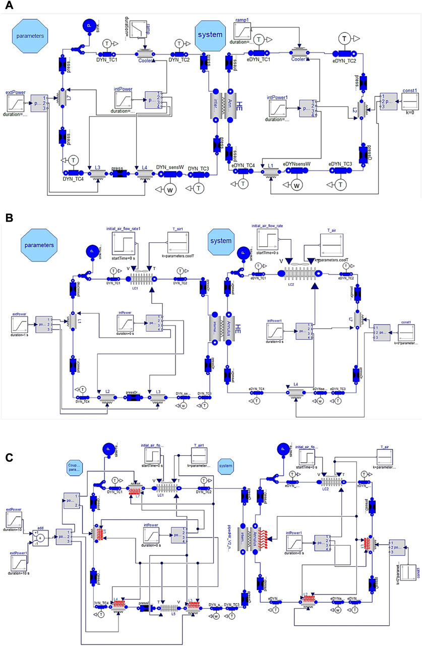
FIGURE 6. Different developed DYNASTY–eDYNASTY models: (A) preliminary adiabatic model with thermostated coolers, (B) adiabatic model with finned coolers, and (C) model with heat losses included.
The developed preliminary coupled facility models were then improved with the addition of the finned pipe cooler and sink pressure, which set the eDYNASTY loop pressure. The facility cooler is modelled as a pipe in the cross flow to account for the heat exchange with air (Bergman et al., 2011), as in the actual physical DYNASTY–eDYNASTY facility, using the same model tested and developed in previous works for the single DYNASTY facility (Cauzzi, 2019; Benzoni et al., 2023). The model uses the Churchill–Bernstein correlation when the fan is turned on (Bergman et al., 2011) and the Churchill–Chu correlation when the fan is turned off (Bergman et al., 2011), accounting for the surface increase due to finning. This model allows for setting the airflow rate to the coolers independently, as in the experimental coupled facility where the deflector allows the use of either the DYNASTY or the eDYNASTY cooler. Furthermore, the model still uses fully adiabatic pipes, which not only eases the simulation process but also allows for future experimental comparison with the insulated coupled facility. The model is shown in Figure 6B. The parameters of finning are the same for both the DYNASTY and eDYNASTY facilities. The model’s main structure is the same as the previous one (shown in Figure 6A), with the same pipes, sensors, and pressure drop layout. The main differences are the two new pairs of inputs connected to “LC1” and “LC2,” which are the DYNASTY and the eDYNASTY cooler, respectively. These new inputs account for the air temperature and the fan airflow rate. All four inputs can be adjusted independently, although the air temperature is assumed to be the same in the two coolers. In this version of the model, due to the adiabatic conditions of the pipe components, the eDYNASTY facility acts mainly as additional thermal inertia for DYNASTY, slowing down the heating process. In principle, the presence of the secondary loop must dampen eventual oscillatory behaviours. However, if the eDYNASTY cooler is used, the additional thermal inertia can behave as a sort of additional insulant layer between the heat source and the heat sink of DYNASTY.
The final coupled DYNASTY–eDYNASTY model which also accounts for the heat loss with the environment is shown in Figure 6C. In the model, except for the HX, the components that build the coupled DYNASTY–eDYNASTY facility are the same as those used in the single DYNASTY loop model (Benzoni et al., 2023). This model also accounts for the section of the DYNASTY mass flow rate metre which acts as a discontinuity to the heating in the horizontal leg. The signal which imposes the air temperature on the outer shell of the pipe components is achieved with two constant input blocks called “T_air” and “T_air1,” which allows to independently set the air temperature to the two loops if needed. This model, like the one shown in Figure 6B, allows to independently set the cooling fan speed to test and analyse the behaviour of the coupled facility when using different configurations.
3.1 Numerical integration algorithm test
In this work, some of the numerical integration algorithms available in Dymola 2023® were tested and analysed to evaluate their performances in solving the problem of natural circulation in coupled loops. The tested algorithms are either single-step or linear multi-step. In particular, the algorithms analysed include implicit Runge–Kutta methods, such as Radau2a (Cellier and Kofman, 2006), Sdirk34hw, and Esdirk45a (Jørgensen et al., 2018), and implicit multi-step methods, such as DASSL (Petzold, 1982) and LSODAR (Hindmarsh and Petzold, 2005). The algorithms chosen for the tests are the ones suggested in the Dymola 2023 user manual for rigid problems (Dassault Systèmes, 2023). The performance tests of this work follow the same logic described by Liu et al. (2010), where the tests used the CPU time as the main metric to provide information on where the algorithms had the most difficulty. Furthermore, the number of events triggered during the simulation was analysed to provide insights into where the model requires higher computation time. The integration algorithm performances were analysed for all the developed models with a user-defined tolerance of 10−6, providing power to the left vertical leg in a vertical heater (VH) configuration and during the first second of the simulations. The simulations were all run on an AMD® Ryzen® 7 5800H processor with the flag “Advanced.ParallelizeCode = true” to enable parallel computing on Dymola 2023®. Furthermore, the models’ discretisation has been reduced to avoid the enormous simulation time observed by Benzoni et al. (2023).
The tests were conducted on the adiabatic model with the finned cooler (shown in Figure 6B) and on the model with the heat losses (shown in Figure 6C). The results for the CPU time and the number of events for the adiabatic model and for the model with heat losses are shown in Figure 7. In the test with the adiabatic model, the outperforming algorithm is the LSODAR one, which managed to complete the simulations faster than the other algorithms for the adiabatic model (as shown in Figures 7A, B). However, both the LSODAR and DASSL algorithms triggered the highest amount of events during the simulation and, when using the LSODAR algorithm to perform simulations longer than 1 s, the algorithm had difficulty with the significant increase in computation time (more than 3,600 s of CPU time to complete the first 50 s of simulation time), without being able to complete the simulations.
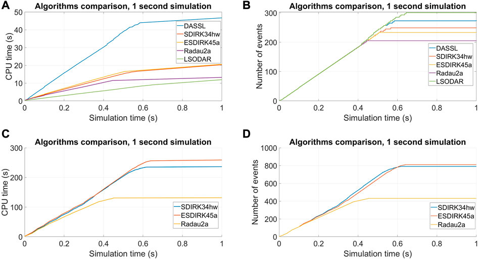
FIGURE 7. 1-s simulation results for different numerical integration algorithms, adiabatic model CPU time (A), adiabatic model number of events (B), model with heat losses CPU time (C), and model with heat losses number of events (D).
The numerical integration algorithm tests continued with the coupled loop model, with heat losses (shown in Figure 6C). This model is significantly more complex than the adiabatic one and is expected to need additional computation time and step size adjustment during the first part of the simulation. The only algorithm that was able to complete the 1-s simulation for the coupled loops, with the heat loss model, was the single-step Runge–Kutta ones (as shown in Figures 7C, D). This is somewhat expected since frequent step adjustments are required in the initial seconds of the simulations, and the multi-step algorithms had the most difficulty (Cellier and Kofman, 2006). These results are also similar to the ones obtained when simulating the single DYNASTY facility with the heat loss model, as the increased complexity caused by heat exchange with air requires more frequent step adjustments when solving the initialisation problem and during the first seconds of the simulation (Benzoni et al., 2023). From these tests, the algorithm chosen for simulating the coupled loop model was the Radau2a algorithm for both the heat loss model and the adiabatic coupled loop case.
4 Preliminary coupled facility model simulation results and discussion
4.1 Analysis on cooler influence on simulation behaviour
The coupled DYNASTY–eDYNASTY facility model in adiabatic configuration with finned coolers allows studying the influence of the cooler position on the simulation behaviour since the model does not include the stabilisation effects of heat losses with the environment. Therefore, some preliminary tests were performed, adopting the same heating configuration; at first, setting 100% of the airflow rate to the DYNASTY facility, while the eDYNASTY cooler was maintained at 0% of the airflow rate, and then setting the eDYNASTY cooler airflow rate at 100%, while keeping the DYNASTY one to 0%. The heating configurations adopted are VH and horizontal heater (HH), with 800 W of heating power, using water in both loops as the working fluid. Figure 8 shows the results for the cooler effect analysis for both the VH and HH configurations. The results of the DYNASTY mass flow rate for the VH configuration are shown in Figure 8A; in the adiabatic configuration with the fan turned off, the single DYNASTY loop model is unable to complete the simulations because it reached high temperatures, as the models are strictly limited to single-phase fluids (Pini, 2017; Cauzzi, 2019; Benzoni et al., 2023). The results for the single DYNASTY loop with the cooler fan at 100% and with the same heating conditions are shown in Figure 8B.
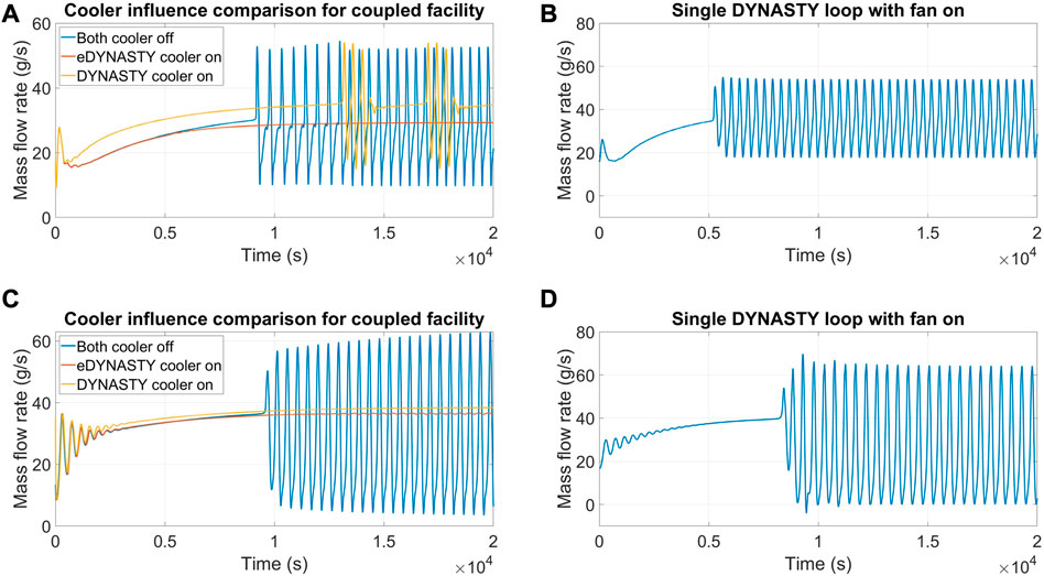
FIGURE 8. Mass flow rate evolution for different coupled loop cooling configurations; (A) VH case, (B) reference to the single DYNASTY loop VHHC case, (C) HH configuration, and (D) reference to the single DYNASTY loop HHHC case.
An interesting outcome is that the addition of the eDYNASTY loop to the DYNASTY one allows the extension of the operative range of the facility. In particular, compared to the DYNASTY single loop, the presence of the added thermal inertia of the eDYNASTY loop, even with 0% airflow rate to both coolers, allows the model to complete the simulations. One of the main reasons is that the additional thermal inertia of the eDYNASTY facility syphons heat from the primary loop, decreasing the maximum fluid temperatures and thus slowing down the heating process. This outcome is also supported by the fact that, for the adiabatic model, the eDYNASTY loop provides additional heat sinks to dissipate the heat supplied to the DYNASTY facility due to the presence of the double-pipe HX and the eDYNASTY cooler. The dampening effects of the eDYNASTY cooler on the mass flow rate evolution for the VH configuration are shown in Figure 8A. In particular, the adoption of the eDYNASTY cooler allows the model to reach a stationary state, in contrast with the oscillatory behaviour exhibited when the airflow rate is not supplied or when it is supplied to the DYNASTY one. Interestingly, the dampening effect of the eDYNASTY cooler outclasses the DYNASTY one, as when the DYNASTY cooler is used, the simulation still exhibits periodic oscillations in the mass flow rate. The influence of the coupled facility cooler configuration was also tested in the HH design. However, this configuration is more prone to unstable behaviour (Vijayan, 2002), so a lower power value of 500 W is adopted to avoid the simulations from crashing (Benzoni et al., 2022b). The remaining simulation parameters and the cooler airflow rate values were kept the same as in the VH case. The results are shown in Figure 8C. The outcomes showed that for the HH configuration, both coolers stabilized the DYNASTY mass flow rate. However, after 12,000 s, the simulations with the eDYNASTY cooler at 100% airflow rate exhibited small oscillations in the mass flow rate. For comparison, the results for the single adiabatic DYNASTY facility is shown in Figure 8D; as in the VHHC configuration, the case with the fan turned off is not able to complete the simulation.
This preliminary comparison highlighted the influence of the cooler configuration on the natural circulation behaviour of the coupled facility. The oscillatory behaviour observed in the simulations is due to a non-balance between the energy supplied to the system and the one dissipated by the system. The comparison shows that depending on the heating configuration, the magnitude of the dampening effect of the two coolers, and thus their relative importance, changes. This behaviour must still be assessed experimentally, which will be carried out in future experimental campaigns on the DYNASTY–eDYNASTY facility. A secondary result of these simulations is that the VH case exhibits, in general, a lower DYNASTY mass flow rate than the HH one. This is compatible with the experimental results in the literature (Pini, 2017; Cauzzi, 2019; Benzoni et al., 2022a), where the symmetric configuration is observed to be the least stable and the one with the highest mass flow rate. A possible reason for the higher mass flow rate of the HHHC configuration (or HH in the coupled facility) can be due to the difference in height of the thermal barycentre of the system (on the single DYNASTY loop), as in the VH configuration, where the heater is closer to the cooler than to the HH configuration (Vijayan, 2002; Pini et al., 2016).
4.2 Preliminary analysis of the coupled DYNASTY–eDYNASTY model with heat losses
Following the implementation of heat losses in the coupled DYNASTY–eDYNASTY model, the simulation results were tested and analysed using a non-insulated model to characterize the influence of thermal losses on the system. In particular, the simulation outcomes were compared with the results of the single DYNASTY loop for the VH and HH configuration (VHHC and HHHC for the single DYNASTY facility), providing the same power to both the single DYNASTY model and the coupled loops (Benzoni et al., 2023) for comparison with the experimental data (825 W for the HHHC case and 1,800 W for the VHHC case), as shown in Figure 9. The values of the airflow rate tested are 0 m3s−1 and 1 m3s−1 to verify the change of correlation when using natural or forced circulating air.
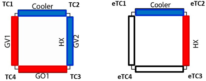
FIGURE 9. Schematic view of the coupled facility model temperature sensor placement.
The results for the HHHC case, with airflow rate 0 m3s−1, are shown in Figure 10, showing the mass flow rate (Figure 10A) and the temperature difference (Figure 10B) along the four DYNASTY legs between the coupled and the single case. In the graphs, the quantities with the label “single loop” refers to the single DYNASTY, while the label “coupled loops” refers to the coupled DYNASTY–eDYNASTY loops. The temperature differences reported are calculated over each section of the loop, in particular, DT1 is TC1–TC2, DT2 is TC2–TC3, DT3 is TC3–TC4, and lastly, DT4 is TC1–TC4 (Figure 9).
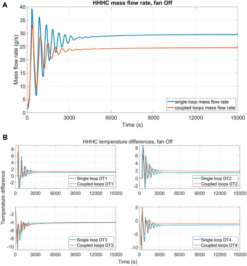
FIGURE 10. Comparison between single DYNASTY and coupled loop simulations with 0% fan speed for HHHC configuration; (A) mass flow rate evolution and (B) temperature difference evolution.
These comparisons show that the behaviour of the curve is not influenced much by the addition of the secondary loop, and the largest differences are in the mass flow rate graph, where at a steady state, the value drops by approximately 16% (5 g/s). In addition, the mass flow rate graph shows a higher dampening of the initial oscillations due to the presence of the secondary intermediate loop. In the temperature difference graph, only a slight decrease in the temperature difference of the HX leg and a slight increase in the temperature difference of the GV1 leg (DT4) are observed.
Figure 11 shows the results using 1 m3s−1 airflow rate (25% of the maximum value) in the HHHC configuration, directing the airflow towards the DYNASTY cooler for the single loop case and towards the eDYNASTY cooler for the coupled case. This has been performed to compare the effectiveness of the dampening effects of the eDYNASTY cooler observed in the adiabatic model and on models that account for the presence of heat losses toward the environment. The results are collected for the DYNASTY mass flow rate (Figure 11A) and for the temperature differences (Figure 11B). In the simulations, the most affected quantities are the DYNASTY loops; although as observed by Benzoni et al. (2022a), the influence of the cooler airflow rate on the experimental facility is limited for the HHHC configuration. This is also observed for the coupled loops, as there are only minor differences between the cases with 25% and 0% airflow rates. The effects of the eDYNASTY loop on the DYNASTY loop are almost identical to the previous case. It is worth noting that the differences in the temperature difference graphs are due to changes in the single loop values, while the coupled loop case curve stays almost constant. This is somewhat expected, as the influence of the eDYNASTY cooler on the coupled system is delayed by the presence of the HX.
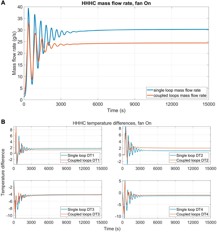
FIGURE 11. Comparison between single DYNASTY and coupled loop simulations with 25% fan speed for HHHC configuration; (A) mass flow rate evolution and (B) temperature difference evolution.
The following cases used the VHHC configuration for the single DYNASTY loop, achieved by powering the GV1 leg as the GV2 one is bypassed by the HX and cannot be used for comparison with the coupled system simulations. The results start with 0% of the airflow rate supplied to the cooler, and then as in the HHHC case, it uses 25% of the airflow rate to the DYNASTY cooler for the single loop case and the eDYNASTY cooler for the coupled loop case. The quantities shown are the DYNASTY mass flow rate and the temperature differences, calculated with the same approach as the HHHC comparison.
The results with 0% airflow rate are shown in Figure 12, in terms of mass flow rate (Figure 12A) and temperature differences (Figure 12B). This configuration exhibits higher differences between the single loop case and the coupled one, as expected from the preliminary adiabatic model results shown in Section 4.1, and it is in contrast with the observations on the HHHC configuration. In these results, the dampening effect of the secondary loop can be appreciated, as the mass flow rate evolves to a stationary state faster than the single loop one. Interestingly, the mass flow rate stationary value of the single DYNASTY loop and of the coupled system is almost equal. The highest differences are observed in the temperature difference graph, where the coupled system shows a faster evolution but with more oscillations. In particular, the coupled system temperature difference, after some oscillations, quickly reaches the steady-state value (before 6,000 s), while the single DYNASTY loop shows a smoother initial transient that requires significantly more time to stabilize after an overshoot of the stationary state value (after 9,000 s).
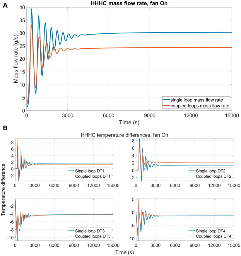
FIGURE 12. Comparison between single DYNASTY and coupled loop simulations with 0% fan speed for VHHC configuration; (A) mass flow rate evolution and (B) temperature difference evolution.
Next, the results with 25% of airflow rate are shown in Figure 13. The simulation parameters are the same as those used for the case with 0% airflow rate. The airflow rate for the coupled system is directed towards the eDYNASTY cooler, as in the HHHC case, to observe the effects on the model with heat losses and to compare it with the DYNASTY cooler influence on the single loop simulations.
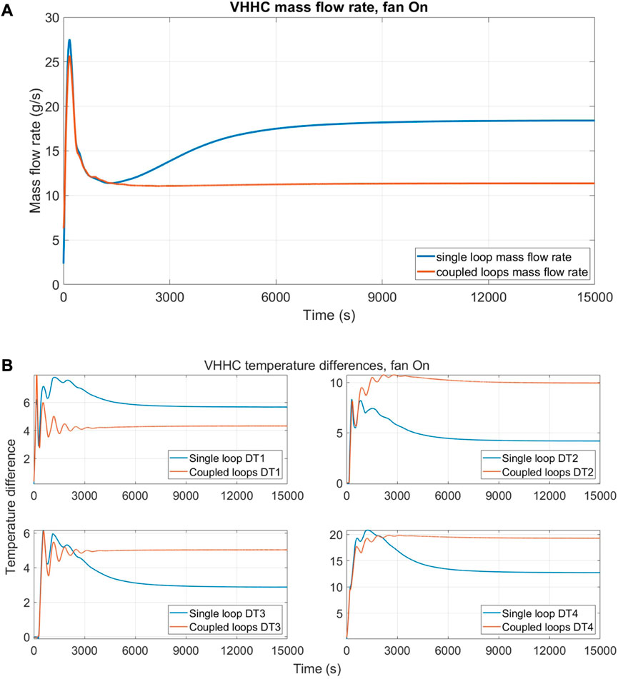
FIGURE 13. Comparison between single DYNASTY and coupled loop simulations with 25% fan speed for VHHC configuration; (A) mass flow rate evolution and (B) temperature difference evolution.
The results of the mass flow rate (Figure 13A) and the temperature difference are collected (Figure 13B), as in the previous cases. In the VHHC configuration, as observed in the experimental analysis on the single DYNASTY loop (Benzoni et al., 2022a), the simulation behaviour is significantly influenced by the airflow rate, since the air regime transition from natural circulation to forced circulation and the correlation used change (Bergman et al., 2011). However, this is true only for the single DYNASTY loop, as the behaviour of the coupled loop significantly differs from the single loop one and resembles the one obtained with 0% of the airflow rate. This is similar to the HHHC case, where the effects of the eDYNASTY cooler on the behaviour of the DYNASTY loop were minimum. A possible explanation is that for the model with heat losses, the effects of thermal losses outclass the effects of the eDYNASTY cooler on the primary DYNASTY loop.
4.3 Coupled loop cooler parametric analysis
To further study the influence of the cooler airflow rate on the coupled loop simulation behaviour, a parametric analysis similar to the one performed by Benzoni et al. (2023) has been carried out. In this analysis, the airflow rate of the DYNASTY cooler is kept constant at zero, while the eDYNASTY one is increased up to 100% of the airflow rate (4 m3s−1). Then, the eDYNASTY airflow rate is kept constant, while the DYNASTY airflow rate to the cooler is increased. Both coolers use the Churchill–Bernstein correlation for finned pipes in a cross flow (Bergman et al., 2011). The heating configuration used is the VH one, as in the adiabatic model, because it was the most affected by the cooling configuration. The quantities of interest in this analysis are the mass flow rate at the stationary state of both the DYNASTY and eDYNASTY loops, the temperature differences between the two coolers, and temperature differences of the double-pipe heat exchanger. The latter was included to study the effects of the cooler airflow rate on the power exchanged between the two loops.
The first results shown are the ones obtained by varying the DYNASTY cooler airflow rate and are shown in Table 1 for the mass flow rates and the coupled facility temperature difference. The number of airflow rate points used is denser for values lower than 1 m3s−1, as the Churchill–Bernstein correlation has an almost logarithmic behaviour with the air velocity (and thus the airflow rate) (Bergman et al., 2011). The starting value of the airflow rate is 0.005 m3s−1 for the DYNASTY cooler, while the eDYNASTY one receives an airflow rate of 0 m3s−1.
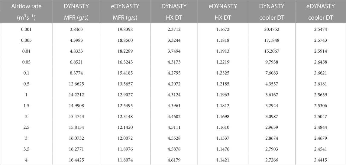
TABLE 1. DYNASTY cooler parametric analysis results, mass flow rate (MFR), and temperature differences (DT).
These results show that when the DYNASTY cooler airflow rate is increased (in the model with the heat losses), the eDYNASTY mass flow rate reduces. The decrease is also observed in the eDYNASTY cooler temperature difference. In the graph, there is also a drastic decrease in the temperature difference value on the DYNASTY side of the HX, which is higher at lower values of the airflow rate. This is expected, as the DYNASTY cooler airflow rate is increased and the eDYNASTY cooler airflow rate is kept constant at 0%, leading to an increase in the effectiveness of the DYNASTY cooler at the expense of the double-pipe HX. This is further highlighted by the increase in the DYNASTY cooler temperature difference and the DYNASTY mass flow rate. Interestingly, the eDYNASTY loop decrease in temperature difference does not happen simultaneously with the mass flow rate. Instead, both eDYNASTY side temperature differences show an increase in values in the first points, which corresponds to the decrease in the mass flow rate. However, when the mass flow rate variations reach a plateau [as expected from the Churchill–Bernstein correlation (Bergman et al., 2011)], the eDYNASTY temperature differences start decreasing.
The following results show the parametric analysis of the eDYNASTY cooler. The coupled system simulation parameters are kept the same as in the DYNASTY cooler analysis. Similar to the previous case, the DYNASTY cooler airflow rate is fixed at 0%. The results are shown in Table 2, for the DYNASTY and eDYNASTY mass flow rates and the coupled system temperature differences. The temperature differences shown are the same as those in the previous case. The starting value of the airflow rate is 0.005 m3s−1 to the eDYNASTY cooler, while the DYNASTY receives an airflow rate of 0 m3s−1.
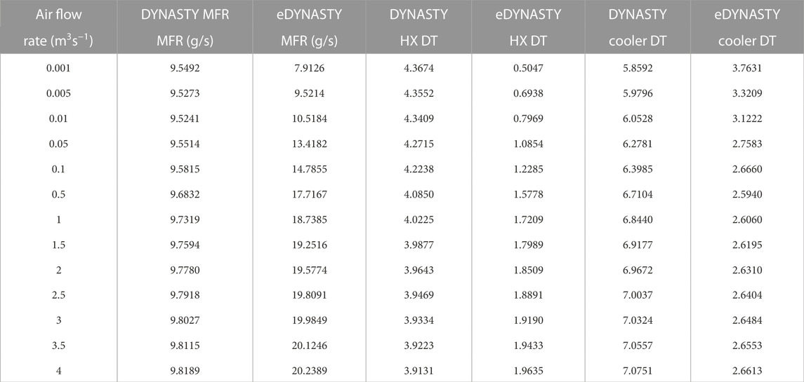
TABLE 2. eDYNASTY cooler parametric analysis results, mass flow rate (MFR), and temperature differences (DT).
These results show a very peculiar behaviour in the DYNASTY and the eDYNASTY mass flow rate increase, albeit the DYNASTY mass flow rate varies only by 0.3 g/s. The eDYNASTY mass flow rate shows a drastic increase in value, similar to the DYNASTY one for the single loop (Benzoni et al., 2023). Furthermore, the DYNASTY cooler temperature difference lowers, while the HX one increases. This means that when the eDYNASTY cooling fan supplies more air, the eDYNASTY loop can extract more heat from the DYNASTY loop, increasing the HX effectiveness and reducing the DYNASTY cooler one. An interesting outcome is that the eDYNASTY side HX temperature difference decreases, compensating for the increase in the mass flow rate, while the DYNASTY HX side increases. The results show a discontinuity in the quantities of interest when compared at an airflow rate of 0 m3s−1, due to the change of correlation that happens as soon as the airflow rate is supplied to the cooler as the model switches from the Churchill–Chu correlation to the Churchill–Bernstein one (Bergman et al., 2011).
5 Conclusion
The author’s work developed the 1D models of the coupled DYNASTY–eDYNASTY facility from the HX, which connects the two natural circulation loops to the models and also accounts for heat losses between the coupled facility and the environment. All the models have been developed and tested using the Dymola® IDE. The tests conducted on the coupled facility involved the analysis of the numerical integration algorithm performances in the simulations and probing the predicted behaviour of the coupled natural circulation loop.
The models of the coupled facility were first developed in a very preliminary way, using adiabatic pipes, an adiabatic HX model (with respect to the environment), and a cooler with imposed temperature. This cooler model was then replaced with a more realistic finned pipe model developed in previous works for the single DYNASTY facility highlighting the adaptability of the Modelica simulation language. Finally, heat losses with the environment were introduced in the coupled DYNASTY–eDYNASTY facility models. To study the capabilities of the numerical integration algorithms to simulate the coupled facility, the ones capable of solving stiff ODE systems were tested on the two more complex models (i.e., the one with heat losses and the adiabatic one with the finned cooler). The analysis observed that the LSODAR algorithm was the most suited for the adiabatic model. In the model with heat losses, the most appropriate algorithm is Radau2a (akin to previous work). However, when performing transient calculations, the LSODAR algorithm cannot complete the whole simulations, leading to the adoption of the Radau2a algorithm in the adiabatic model. Nonetheless, these tests are only valid on these coupled DYNASTY–eDYNASTY models and can be subject to change in future iterations of DYMOLA®.
The developed models, both the adiabatic and the ones with heat losses, were then used to simulate the behaviour of the coupled DYNASTY–eDYNASTY facility. The simulations focused, in particular, on analysing the effects of the added thermal inertia of the eDYNASTY facility on the primary DYNASTY one. Analysis of the adiabatic model with the finned cooler showed that the influence of the eDYNASTY cooler outperforms the DYNASTY one in dampening eventual oscillatory behaviours for the VHHC configuration. However, in the HHHC configuration, both coolers have similar effects, although some oscillations are observed with the eDYNASTY cooler after 12,000 s. These oscillations occur due to a non-stable equilibrium between the driving force and friction losses. Furthermore, the simulation results of the coupled DYNASTY–eDYNASTY loop with the added heat loss were compared with the single DYNASTY facility to more thoroughly analyse the influence of the addition of the secondary loop. In the model, the insulation was removed to also study the influence of heat loss on the coupled facility. These preliminary comparisons showed that the temperature difference for the HHHC case is not influenced in a relevant way by the addition of the secondary loop. However, the eDYNASTY loop decreases the overall value of the DYNASTY mass flow rate and has a faster dampening of the initial oscillations. In the VHHC case, the differences are more relevant since this design is more dependent on the cooler airflow rate. However, using the eDYNASTY cooler does not influence the DYNASTY mass flow rate. This leads to a marked difference in the case with a 25% airflow rate between the single loop simulations and the coupled ones. Also, the VHHC configuration shows a higher dampening effect of the secondary loop than that observed in the HHHC case, particularly in the temperature graphs. Finally, to further analyse the influence of the cooling configuration of the coupled system on the simulation behaviour, a parametric analysis, varying the airflow rate on each cooler, has been performed. This analysis involved delivering increasing values of airflow rate to the analysed cooler (first, the DYNASTY one, and then, the eDYNASTY one), while maintaining the airflow rate of the other cooler at 0% (i.e., 0 m3s−1). The results of the coolers’ parametric analysis performed on the model with heat losses showed that increasing the value of the airflow rate to the eDYNASTY cooler leads to an increase in the effectiveness of the double-pipe HX, which translates to a higher eDYNASTY mass flow rate and cooler temperature difference. When the DYNASTY cooler airflow rate is increased, the HX influence on the simulations decreases and the eDYNASTY mass flow rate and temperature difference also decreased. This translates to a decrease in the influence of the secondary loop on the behaviour of the primary one.
These preliminary results highlighted the need for further simulation and experimental analysis. These analyses aimed at comparing the performances of the single DYNASTY loop and the coupled facility when the heating power is either reduced or increased (e.g., during cooling or a heating ramp) to observe the effects of the added thermal inertia of the eDYNASTY loop on the DYNASTY loop. In particular, this study aimed to analyse if eDYNASTY can dampen eventual oscillations in power transients. Further improvements will also involve simulation comparisons with experimental data, focussing on analysing the predicted behaviour with different levels of cooler airflow rate and probing the overall predicting capabilities of the model.
Data availability statement
The datasets presented in this study can be found in online repositories. The names of the repository/repositories and accession number(s) can be found at Zenodo at: http://doi.org/10.5281/zenodo.7520616.
Author contributions
GB conceived the modelling approach and performed the simulations. GB and CI analysed the simulation results with support from AC and SL. GB wrote the manuscript with support from CI and LL. AC and SL conceived the original idea. AC supervised the project. All authors have read and agreed to the published version of the manuscript.
Acknowledgments
This project has received funding from the Euratom Research and Training Programme 2014–2018 under grant agreement no. 847527.
Conflict of interest
The authors declare that the research was conducted in the absence of any commercial or financial relationships that could be construed as a potential conflict of interest.
Publisher’s note
All claims expressed in this article are solely those of the authors and do not necessarily represent those of their affiliated organizations, or those of the publisher, the editors and the reviewers. Any product that may be evaluated in this article, or claim that may be made by its manufacturer, is not guaranteed or endorsed by the publisher.
Author disclaimer
The content of this paper does not reflect the official opinion of the European Union. Responsibility for the information and/or views expressed therein lies entirely with the authors.
References
Battistini, A., Cammi, A., Lorenzi, S., Colombo, M., and Fairweather, M. (2021). Development of a cfd – Les model for the dynamic analysis of the dynasty natural circulation loop. Chem. Eng. Sci. 237, 116520. doi:10.1016/j.ces.2021.116520
Benzoni, G., Cammi, A., Introini, C., Lorenzi, S., and Colombo, M. (2022a). “Preliminary results of the experimental campaign conducted on the dynasty natural circulation loop,” in 19th international topical meeting on nuclear reactor thermal hydraulics (NURETH 19), Brussels, Belgium, 35761.
Benzoni, G., Introini, C., Lorenzi, S., and Cammi, A. (2022b). “Preliminary 1D modelling of the coupled DYNASTY-eDYNASTY experimental facility,” in 13th international topical meeting of nuclear reactor thermal-hydraulics, operation and safety proceedings (NUTHOS-13), Hsinchu, Taiwan, 1, 244–256.
Benzoni, G., Introini, C., Lorenzi, S., and Cammi, A. (2023). Preliminary validation of the 1d modeling of the dynasty natural circulation loop against results from water experimental campaign. Prog. Nucl. Energy 155, 104486. doi:10.1016/j.pnucene.2022.104486
Bergman, T. L., Lavine, S., Incropera, A., P., and dewitt, D. P. (2011). Fundamentals of heat and mass transfer. Seventh Edition. New Jersey, United States: John Wiley & Sons, Inc.
Cammi, A., Cauzzi, M. T., Luzzi, L., and Pini, A. (2016a). “Dynasty: An experimental loop for the study of natural circulation with internally heated fluids,” in 12th international conference on heat transfer, fluid mechanics and thermodynamics, Malaga, Spain, 1159–1164.
Cammi, A., Luzzi, L., and Pini, A. (2016b). The influence of the wall thermal inertia over a single-phase natural convection loop with internally heated fluids. Chem. Eng. Sci. 153, 411–433. doi:10.1016/j.ces.2016.06.060
Casella, F., and Leva, A. (2003). “Modelica open library for power plant simulation: Design and experimental validation,” in Proceedings of the 3rd international Modelica conference, Linköping, Sweden, 41–50.
Casella, F., and Leva, A. (2005). “Object-oriented modelling & simulation of power plants with Modelica,” in Proceedings of the 44th IEEE conference on decision and control (New Jersey, United States: IEEE), 7597–7602. doi:10.1109/CDC.2005.1583388
Cauzzi, M. T. (2019). Modelling and experimental investigation of natural circulation in presence of distributed heating. Milan, Italy: Politecnico di Milano.
Cellier, F. E., and Kofman, E. (2006). Continuous system simulation. Dordrecht, Netherlands: Kluwer Academic Publishers. doi:10.1007/0-387-30260-3
ELSI (1998). General purpose Mgo sensors with connection head. Available at: http://www.elsi.it/en/products/thermocouple/ELSI_TC_Q1_UK.pdf.
Elton, D., Arunachala, U., and Vijayan, P. (2022). Stability performance of series coupled natural circulation system with different operating procedures. Int. J. Therm. Sci. 179, 107693. doi:10.1016/j.ijthermalsci.2022.107693
Endress-Hauser (2016). Endress+Hauser. Available at: https://www.it.endress.com/en/field-instruments-overview/flow-measurement-p roduct-overview/Product-Coriolis-flowmeter-Proline-Promass-80F.
Fritzson, P. (2014). Principles of object oriented modeling and simulation with Modelica 3.3: A cyber-physical approach. New Jersey, United States: John Wiley & Sons, Ltd. doi:10.1002/9781118989166
Hindmarsh, A., and Petzold, L. (2005). LSODAR, ordinary differential equation solver for stiff or non-stiff system with root-finding. Vienna, Austria: INIS IAEA.
Jeong, Y. S., Seo, S. B., and Bang, I. C. (2018). Natural convection heat transfer characteristics of molten salt with internal heat generation. Int. J. Therm. Sci. 129, 181–192. doi:10.1016/j.ijthermalsci.2018.01.036
Jørgensen, J. B., Kristensen, M. R., and Thomsen, P. G. (2018). “A family of esdirk integration methods,” in arXiv Mathematics Numerical Analysis. doi:10.48550/arXiv.1803.01613
Liu, L., Felgner, F., and Frey, G. (2010). “Comparison of 4 numerical solvers for stiff and hybrid systems simulation,” in Proceedings of the 15th IEEE international conference on emerging technologies and factory automation, ETFA 2010, Bilbao, Spain, (IEEE). doi:10.1109/ETFA.2010.5641330
Misale, M., and Garibaldi, P. (2010). “Dynamic behaviour of a rectangular single-phase natural circulation loop: Influence of loop inclination,” in 20th national and 9th international ISHMT-ASME heat and mass transfer conference, Mumbai, India, 353.
Nalbandyan, A., Cammi, A., Lorenzi, S., Klinkby, E. B., and Lauritzen, B. (2022). Modelling and cfd analysis of the dynasty loop facility. EPJ Nucl. Sci. Technol. 8, 12. doi:10.1051/epjn/2022010
Pantelides, C. C. (1988). The consistent initialization of differential-algebraic systems. SIAM J. Sci. Stat. Comput. 9, 213–231. doi:10.1137/0909014
Petzold, L. (1982). “A description of DASSL: A differential/algebraic system solver,” in 10th international mathematics and computers simulation congress on systems simulation and scientific computation, Montreal, Canada, U.S. Department of Energy Office of Scientific and Technical Information.
Pini, A. (2017). Analytical and numerical investigation of natural circulation dynamics in presence of distributed heat sources. Milan, Italy: Politecnico di Milano.
Pini, A., Cammi, A., and Luzzi, L. (2016). Analytical and numerical investigation of the heat exchange effect on the dynamic behaviour of natural circulation with internally heated fluids. Chem. Eng. Sci. 145, 108–125. doi:10.1016/j.ces.2016.01.014
Rassame, S., Hibiki, T., and Ishii, M. (2017). Esbwr passive safety system performance under loss of coolant accidents. Prog. Nucl. Energy 96, 1–17. doi:10.1016/j.pnucene.2016.12.005
Ruiz, D. E., Cammi, A., and Luzzi, L. (2015). Dynamic stability of natural circulation loops for single phase fluids with internal heat generation. Chem. Eng. Sci. 126, 573–583. doi:10.1016/j.ces.2014.12.050
Schmid, P. J., and Brandt, L. (2014). Analysis of fluid systems: Stability, receptivity, sensitivity. Appl. Mech. Rev. 66, 024803. doi:10.1115/1.4026375
Serp, J., Allibert, M., Beneš, O., Delpech, S., Feynberg, O., Ghetta, V., et al. (2014). The molten salt reactor (MSR) in generation IV: Overview and perspectives. Prog. Nucl. Energy 77, 308–319. doi:10.1016/j.pnucene.2014.02.014
Sutharshan, B., Mutyala, M., Vijuk, R. P., and Mishra, A. (2011). The ap1000tm reactor: Passive safety and modular design. Energy Procedia 7, 293–302. doi:10.1016/j.egypro.2011.06.038
TYFOPROP(2020). TYFOCORLS en TI. Available at: https://tyfo.de/downloads/TYFOCORLS_en_TI.pdf.
Vijayan, P. K. (2002). Experimental observations on the general trends of the steady state and stability behaviour of single-phase natural circulation loops. Nucl. Eng. Des. 215, 139–152. doi:10.1016/S0029-5493(02)00047-X
Keywords: natural circulation, Modelica 1D modelling, DYNASTY–eDYNASTY, parametric analysis, coupled natural circulation
Citation: Benzoni G, Introini C, Lorenzi S, Loi L and Cammi A (2023) 1D modelling and preliminary analysis of the coupled DYNASTY–eDYNASTY natural circulation loop. Front. Energy Res. 11:1165179. doi: 10.3389/fenrg.2023.1165179
Received: 13 February 2023; Accepted: 20 March 2023;
Published: 11 April 2023.
Edited by:
Xiang Wang, Harbin Engineering University, ChinaReviewed by:
Pengcheng Zhao, University of South China, ChinaTian Zhang, Harbin Engineering University, China
Ao Zhang, Harbin Engineering University, China in collaboration with reviewer TZ
Copyright © 2023 Benzoni, Introini, Lorenzi, Loi and Cammi. This is an open-access article distributed under the terms of the Creative Commons Attribution License (CC BY). The use, distribution or reproduction in other forums is permitted, provided the original author(s) and the copyright owner(s) are credited and that the original publication in this journal is cited, in accordance with accepted academic practice. No use, distribution or reproduction is permitted which does not comply with these terms.
*Correspondence: Antonio Cammi, YW50b25pby5jYW1taUBwb2xpbWkuaXQ=