 Kent Welter
 José N. Reyes
 - NuScale Power, Corvallis, OR, United States
Small modular reactors (SMR) offer a novel approach to the construction and operation of nuclear power plants. The NuScale VOYGR™ plant uses a simplified SMR design that is based on proven light-water reactor technology with substantial improvements in nuclear safety. It consists of a 250 MWt reactor core housed with other primary system components in an integral reactor pressure vessel surrounded by a steel containment vessel, all of which is immersed in a large pool of water that also serves as the ultimate heat sink. At the core of the NuScale safety case are three primary safety systems: the decay heat removal system, the emergency core cooling system, and the containment. The ability of the NuScale Power Module (NPM) passive safety systems to remove core decay heat for an unlimited duration is demonstrated through analysis of a beyond-design-basis extended loss of AC power with no replenishment of water to the ultimate heat sink or operator actions. The NuScale methodology to evaluate an indefinite loss of AC power uses the proprietary NRELAP5 systems analysis computer code. Analysis results show that the reactor coolant system liquid level above the core is maintained and that containment pressure remains below the vessel design pressure. Once full passive air cooling is established, containment pressure and temperature will decrease over time with decreasing core decay heat. NuScale received standard design approval in September 2020 and design certification in January 2023 for its 50 MWe NPM configured as a 12 module plant. NuScale is currently seeking standard design approval to increase its core power to 250 MWt, nominally 77 MWe per module, in a 6-module plant (VOYGR™-6) configuration. The high-level safety of NuScale’s SMR technology is foundational to a new standard of nuclear power plant resilience.
1 NuScale plant VOYGR™ overview
The NuScale plant, known as VOYGR™, uses a simplified, small modular reactor (SMR) that is based on proven light-water reactor technology with substantial improvements in nuclear safety. The innovative design is elegantly simple, incorporates extensive use of passive safety features, meets the utility needs for standardization while also allowing flexible deployment options, and is scalable to allow for incremental increases in electrical generating capacity. The robust design, small fuel inventory, and multiple barriers preventing fission product release contribute to a low probability and consequence of radionuclide release even under extreme upset conditions, thus simplifying the emergency preparedness and response, and providing a basis for reducing the emergency planning zone (EPZ) to the site boundary.
The NuScale plant consists of multiple power units, with each unit representing an independent nuclear steam supply system coupled to a dedicated turbine-generator system. A flexible number of NuScale Power Modules (NPMs) can be configured into the plant to suit a utility’s needs. Each NPM produces 77 MWe, with the 6-unit plant producing 462 MWe gross at rated conditions (see Figure 1 below). The NPMs are located in a water-filled reactor pool, which provides an assured passive heat sink for safe shutdown. The scalable design allows for initial power generation from installation and startup of the first unit with additional plant capacity being added incrementally to meet utility needs.
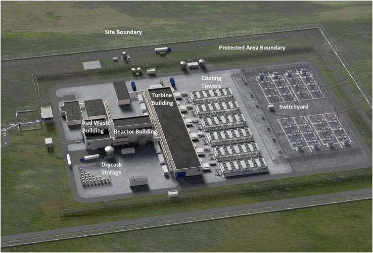
FIGURE 1. Overview of VOYGR-6 plant.
The NuScale model provides a means of deploying nuclear power plants in an expeditious and affordable manner while maintaining a high-level of quality, safety, and security. Customer investment is protected through defense-in-depth design strategies that rely on physics-based principles to remove decay heat and maintain fuel integrity. Maximizing design simplicity and modularizing the plant into small, standard, factory-built equipment packages further help to accomplish these objectives.
The NuScale design includes a number of significant innovations that distinguish it from not only large light-water reactor (LWR) plants but also other SMR designs. Key innovations include:
• Design-related innovations
• Integral primary system design with natural circulation of the primary coolant
• Unique containment vessel that is a compact high-pressure steel vessel immersed in a large pool of water and operating at a deep vacuum
• Shared reactor pool to provide an assured ultimate heat sink
• Compact, high-efficiency pair of co-mingled, helical coil steam generators
• Secondary side passive decay heat removal system
• Simplified, passive emergency core cooling system (ECCS) that uses inherent design features to provide greatly extended emergency response times
• An alternative solution to safety grade power requirements that simplify battery requirements
• An industry-leading risk- and testing-informed design process
• Operational-related innovations
• In-factory fabrication of the NPMs, including containment, with truck, rail or barge shipment to the site
• Continuous power operation with one module being refueled while the other modules are operating
• Flexibilities for staged installation of modules and build-out of the site to best match a customer’s power demand profile
• Unique adaptability to non-electrical applications due to small, independent power units
• Island mode capability that allows operation of the NPMs without a connection to a transmission grid
These innovations are the deliberate consequence of the top-level design objectives of enhanced safety, flexibility, and increased affordability. In most cases, the innovations are in the design and engineering of the plant rather than the underlying technology, which builds on the vast global experience with LWRs.
1.1 Reactor configuration
The NPM, shown in Figure 2, is the fundamental building block of NuScale VOYGR™ power plant. It consists of a 250 MWt reactor core housed with other primary system components in an integral reactor pressure vessel surrounded by a steel containment vessel, all of which is immersed in a large pool of water that also serves as the ultimate heat sink.
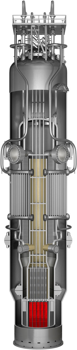
FIGURE 2. Cutaway of a NuScale power Module™.
Above the core, there is a central hot riser tube, a helical coil steam generator surrounding the hot riser tube, and a pressurizer. The helical coil steam generator consists of two independent and interleaved sets of tube bundles with separate feedwater inlet and steam outlet lines. Sets of pressurizer heaters and spray nozzles located in the upper head of the vessel provide pressure control.
The primary reactor coolant path is upward through the reactor core. Heated water flows upward through the hot riser tube due to buoyancy forces and is turned downward at the pressurizer baffle plate. It then flows over the shell side of the steam generator, where it is cooled by conduction and convection of heat to the secondary coolant and continues to flow downward until its direction is again reversed at the lower reactor vessel head and turned upward back into the core. Coolant circulation is maintained entirely by natural buoyancy forces of the lower-density heated water exiting the core and the higher-density cooled water exiting the steam generator annulus.
The reactor vessel is enclosed in a stainless steel containment vessel (CNV) that is nominally 76 ft tall and 19 ft in diameter. The small-volume, high-design-pressure CNV is a unique feature of the NuScale design that contributes significantly to the large safety margins and overall resilience. The CNV has been designed as an ASME Class 1 pressure vessel. As a result, it can safely contain any loss-of-coolant-accident (LOCA) that can occur inside containment. During normal power operation, the CNV atmosphere is evacuated to provide an insulating vacuum that significantly reduces parasitic heat loss from the reactor vessel.
The reactor vessel internals (RVI) support the reactor core, the control rod assemblies (CRAs), and the control rod drive shafts. The RVI channel the flow from the reactor core to the steam generators within the reactor pressure vessel (RPV).
The NPMs are located below grade in a nominally 2.8 million gallon (for a 6-unit building), stainless steel-lined pool of water that is contained in a Seismic Category I reactor building. Each NPM is operated in its own bay, immersed in a pool of water which is approximately 20 ft square by 53 ft deep (see Figure 3). The pool provides passive containment cooling and decay heat removal (i.e., an assured heat sink with a capacity to absorb all decay heat produced by all reactors for more than 30 days. The pool also reduces and delays the release of fission products in the unlikely event of fuel, primary system, and containment vessel failure and provides radiation shielding outside containment to reduce operational exposure. The pool enhances physical security by adding an additional barrier to fuel access.
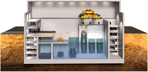
FIGURE 3. NuScale reactor building cutaway.
An overhead reactor building crane is utilized to upend and import module components into the reactor building during installation, move modules during refueling, support spent fuel storage cask movement, and support module removal during decommissioning. Flange tools are located within the pool which perform remote bolting of containment and reactor vessel flanges. These tools also incorporate provisions to support remote monitoring of critical equipment and neutron monitors to support refueling activities.
2 Passive safety and defense-in-depth
The VOYGR’s revolutionary safety features provide stable, long-term nuclear core cooling under all conditions, including severe accidents. These features include:
• The ability to safely shut down and self-cool for an unlimited amount of time with no operator action, no AC or DC power, and no additional water. This is a first for commercial nuclear power.
• A high-pressure containment vessel, redundant passive decay heat removal, and containment heat removal systems.
• An integrated reactor design that eliminates the need for large primary piping and reactor coolant pumps.
• A small nuclear fuel inventory, with each NPM housing approximately 5 percent of the nuclear fuel contained in a conventional 1,000 MWe nuclear reactor.
• A containment vessel submerged in an ultimate heat sink for core cooling in a below grade reactor pool structure that’s housed in a Seismic Category 1 reactor building.
2.1 Defense-in-depth
The NuScale defense-in-depth methodology utilizes five levels, along with evaluation of qualitative and quantitative attributes associated with each level. These five levels are listed below and are consistent with the International Atomic Energy Agency (IAEA), 1996 defense-in-depth guidelines:
• Level 1. Prevention of abnormal operation and failures which would initiate the accident sequence
• Level 2. Control of abnormal operation and detection of the failures associated with accident initiation so as to prevent further deterioration of plant status
• Level 3. Control of the accident sequence within the design basis so as to prevent core damage
• Level 4. Control of beyond-design-basis conditions, including limiting core damage progression and providing containment of any resulting fission product release from the damaged core
• Level 5. Mitigation of the consequences of releases of radioactive materials which could result from the accident sequence if the containment function is impaired
The assessment of defense-in-depth for sequence screening employs a risk-informed, performance-based approach, which utilizes attributes in the form of risk metrics, design features, and operational features. Some of the attributes, particularly the risk metrics, are quantitative, and others are qualitative. Thus, while the approach relies on engineering judgment, it involves both quantitative and qualitative attributes and associated attribute valuation. This is much more structured and transparent than a purely qualitative approach to assessing defense-in-depth.
With respect to level one’s goal of a robust design and quality construction that will provide confidence that plant failures and deviations from normal operations are minimized and accidents are prevented, NuScale has implemented a Reliability Assurance Program (RAP), Quality Assurance Program (QAP), and Human Factors Engineering (HFE) Program. The RAP, QAP, and HFE program provide assurance that the NuScale plant will be designed, constructed, operated, and maintained in a manner that meets the level one defense-in-depth objectives.
The level two defense-in-depth goals are met by a combination of robust engineered control systems and inherent plant capability. The NuScale design includes digital, fault tolerant, diverse, and redundant control and protection systems that automatically control the majority of the plant systems. The control and protection systems are monitored and can be manually controlled by the operators in the control room, if needed. In general, control systems are non-safety, but designed with augmented quality, and the protection systems are safety-related.
In addition to the digital control and protection systems that automatically provide plant control and protection, the plant operators are provided with a full suite of operating limits and procedures that contribute to ensuring that the possibility of abnormal plant transients that could deteriorate to an accident condition are minimized to the greatest extent practical.
The combination of automatic and manual control will detect deviations from normal and provide actions that will prevent the plant from progressing to an accident condition, thus meeting the goal of level two defense-in-depth.
Level three defense-in-depth for the NuScale design is provided by numerous inherent safety features and automatic, fail-safe systems. The NuScale design features an inherently stable core, simple and passive safety systems, and no operator action or electrical power required for design basis events. The inherent design and engineered features minimize the consequences of accidents and maintain at least one confinement barrier under all credible accident conditions.
The goal of defense-in-depth level four is to manage accidents and mitigate their consequences in the unlikely event one occurs. In the case of NuScale design, the containment will continue to provide a robust barrier to the release of fission products as described under level three. In addition, even in the case of a loss of reactor coolant inventory, detailed analysis demonstrates that the core will remain inside the containment due to significant heat transfer through containment to the ultimate heat sink. Therefore, containment remains a substantial fission product barrier and additional level of defense-in-depth.
Level five defense-in-depth consists of personnel, facilities, and procedures for emergency management. The emergency plans will consist of emergency plan procedures, onsite facilities for personnel staging, communications, emergency response equipment, on and off-site radiological monitoring, personnel protection, and other capabilities as provided for the site emergency response. However, because of the safety of the NuScale design, the plume exposure emergency planning zone only extends to the site boundary, practically eliminating the need for emergency plan development beyond the site boundary.
Table 1 provides a comparison of NuScale defense-in-depth features against a conventional (i.e., Generation II) LWR.
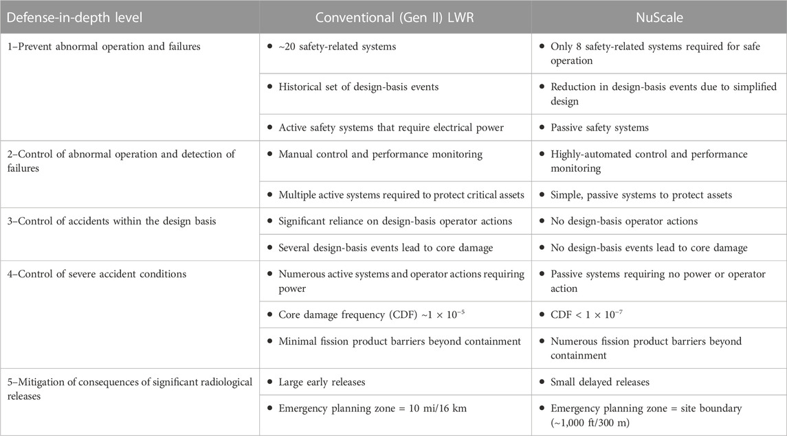
TABLE 1. NuScale defense-in-depth comparison to a conventional LWR.
2.2 Passive safety systems
At the core of the NuScale safety case are three primary safety systems: (1) the decay heat removal system (DHRS), which removes heat from the reactor coolant system (RCS) via the steam generators; (2) the emergency core cooling system (ECCS), which vents the reactor vessel to the containment in order to remove heat and maintain a flow path back to the reactor core; and (3) the containment system (CNT), which includes the containment vessel itself and the isolation valves, which create a pressure boundary for both the ECCS and DHRS. The systems all use valves that fail to their safe position on a loss of power, meaning that safety system operation is ensured without reliance on electrical power. When power is available, the systems are controlled via a dedicated safety-related module protection system (MPS), which monitors various plant conditions and actuates the safety systems if required. The NPMs themselves are located in a common reactor pool, which serves as the ultimate heat sink for the safety systems, and are located in the Seismic Category I reactor building.
2.2.1 Decay heat removal system
The DHRS is a closed-loop, two-phase natural circulation cooling system that operates on the secondary side (see Figure 4B). Two trains of decay heat removal equipment are provided, one for each steam generator. Each train is capable of removing 100 percent of the decay heat load and cooling the RCS by means of the DHRS condenser, which is submerged in the reactor pool. The condensers are maintained with sufficient water inventory for stable operation. When responding to a design basis event and upon receipt of an actuation signal, the DHRS isolation valves open and the secondary system (main steam and feedwater) isolation valves close. Water from the decay heat removal condensers travels to the steam generators and cools the reactor coolant as it is turned to steam. The steam travels through the steam generator back to the DHRS condenser where it is condensed by the reactor pool water, and the cycle is repeated. Heat is removed via the steam generators, preserving natural circulation within the RCS.
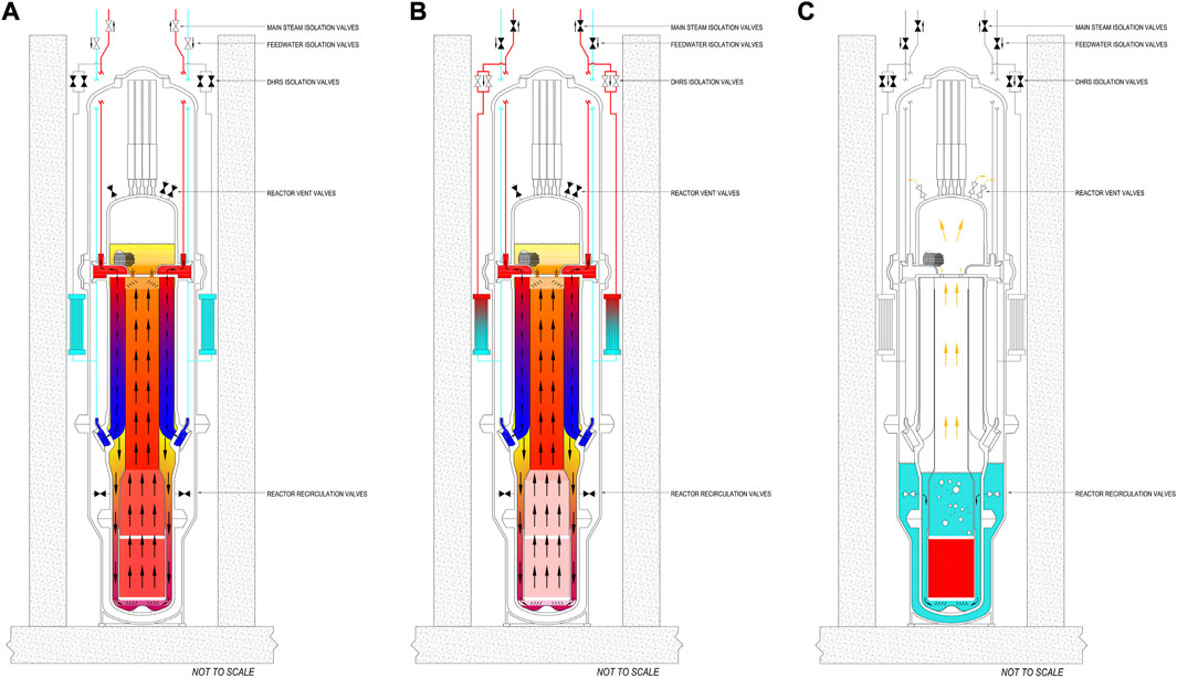
FIGURE 4. (A) Normal Operation, (B) The DHRS is a secondary-side system that passively removes core decay heat, (C) The ECCS is a primary-side system that passively removes core decay heat.
2.2.2 Emergency core cooling system
The ECCS is a closed-loop, two-phase natural circulation cooling system that operates on the primary side (see Figure 4C). The system is initiated by opening the two reactor vent valves at the top of the reactor pressure vessel (the pressurizer region) and the two fail-safe reactor recirculation valves on lines entering the reactor pressure vessel in the downcomer region at a height above the core. Water vaporized in the core leaves as steam through the reactor vent valves, condenses and collects in the containment, and returns to the downcomer region inside the reactor vessel through the reactor recirculation valves. The ECCS removes heat and limits containment pressure by steam condensation on the inside surface of the containment vessel, and allows heat conduction and convection to the water in the reactor pool. Additionally actuation of the ECCS increases boron concentration in the reactor through dissolving strategically located boron pellets in the upper containment vessel. This feature is used to ensure sufficient shutdown margin during specific long term events. Following a LOCA or other condition resulting in an actuation of the ECCS, heat removal through the containment vessel rapidly reduces the containment pressure and temperature and maintains them at acceptably low levels for an unlimited period of time. As summarized by Morton (2019), the data generated by NuScale’s thermal-hydraulic integral system test facility, or “NIST,” demonstrate the design concept that the ECCS keeps the fuel covered with water while providing long-term cooling, and provides test data for validation of safety analysis codes.
2.2.3 Containment and ultimate heat sink
The NuScale containment vessel will be constructed and stamped as an ASME Section III - Class 1 Vessel. The containment vessel is designed for a maximum internal pressure of 1,200 psi with a concomitant metal temperature of 600°F.
During normal operating conditions, the CNV is maintained at sub-atmospheric conditions, less than 1 psia internal pressure. This reduces the potential for a flammable atmosphere during severe accidents and insulates the RPV during operation.
The containment vessel is manufactured in a factory and delivered to the site, integrated with each NPM. The factory manufacturing of the steel containment maximizes efficiency and quality control by shifting work from the field to a controlled environment.
Recovery from a blowdown event is also improved from other reactor designs. The compact steel containment with little internal equipment is designed to operate in a borated water environment during shutdown. As a result, contamination due to blowdown will not require extraordinary cleanup processes.
All containment isolation valves (CIVs) are passive fail-closed designs. No electric power or operator action is required to accomplish the containment isolation function.
The reactor pool is a large below-grade pool that provides stable cooling for the immersed NPMs. During normal plant operations (Figure 4A), heat is removed from the pool through a closed loop cooling system and ultimately rejected into the atmosphere. If power is lost, heat is removed from the modules by allowing the pool to heat up and boil. During the first 30 days post-accident, the pool absorbs the decay heat from the modules and eventually begins to boil. After 30 days, water boil-off and passive air cooling of the modules provide adequate cooling for an unlimited period of time (Figure 5). This extremely robust safety feature is a direct consequence of the reactor pool providing an assured supply of long-term cooling.
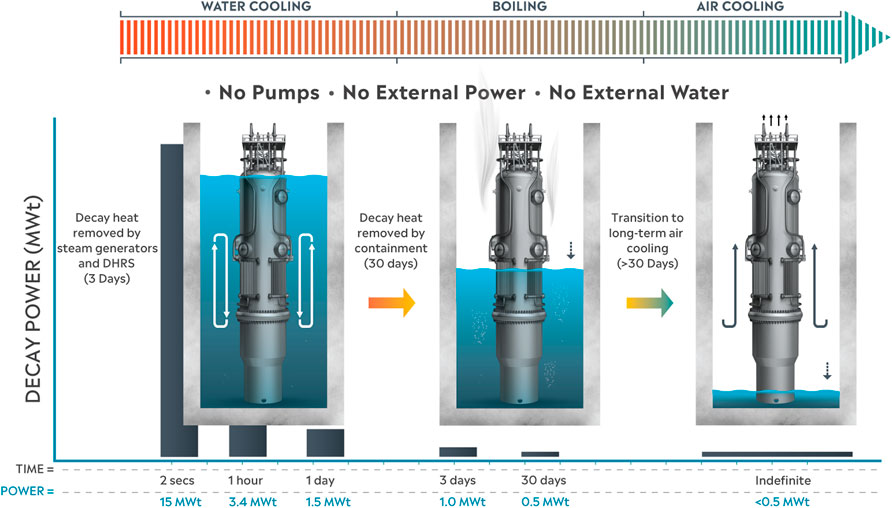
FIGURE 5. Long-term NPM cooling without power or makeup water.
2.2.4 Demonstration of passive safety systems for beyond-design-basis loss of power scenario
The ability of the NPM passive safety systems to remove core decay heat for an unlimited duration is demonstrated through analysis of a beyond-design-basis extended loss of AC power with no replenishment of water to the ultimate heat sink or operator actions. This scenario assumes an initiating event causes an indefinite loss of AC power to the plant with all 6 modules initially operating at 250 MWt reactor power. In response, the module protection systems will automatically initiate reactor scram and actuate the DHRS to provide passive cooling. If the loss of power persists, the protection systems will also actuate the ECCS to ensure sufficient boron concentration exists in the core to maintain long-term shutdown margin. With 6 modules rejecting decay heat through the DHRS and ECCS, the reactor pool will eventually heat up and boil. Additional water to re-fill the pool is assumed unavailable even though means exist to easily refill the pool via a seismically qualified fill line accessible from outside the reactor building. Water boil-off will uncover the DHRS condenser by 30 days and the pool will be effectively empty by 99 days. Passive air cooling will become an increasingly large contributor to decay heat removal. The ability of the DHRS and ECCS to remove decay heat under this scenario is confirmed by demonstrating that the core remains covered by RCS liquid inventory at all times and containment remains below the vessel design pressure.
The NuScale methodology to evaluate an indefinite loss of AC power uses the proprietary NRELAP5 systems analysis computer code, derived from the Idaho National Laboratory (INL) RELAP5-3D© code, to simulate the module thermal-hydraulic conditions over time. Reactor pool temperature and pool level are calculable as a function of integral decay heat from 6 modules and the thermal capacity of the initial water inventory. Pool conditions are input as a boundary condition to the NRELAP5 plant model. Given the long multi-day evaluation window, the analysis method takes advantage of the long-term, quasi-equilibrium cooling transient as both decay heat and pool level slowly decrease over time. Rather than performing a single long-running simulation, significant computation time is saved by executing multiple simulations in parallel where each case represents a number of days since the loss of power occurred. For each case, reactor pool conditions and core decay heat calculated for that day are input as constant boundary conditions to the plant model. The simulations are executed until module internal pressures and temperatures converge to steady-state values. These converged values are representative of module conditions at that point in time. The performance of this method is confirmed by benchmarking against a full transient simulation period of 3 days past event initiation.
Analysis results show that the RCS liquid level above the core is maintained and that containment pressure remains below the vessel design pressure. The RCS liquid level is primarily a function of initial RCS inventory, volume distribution between the CNV and RPV, and the ECCS valve flow capacity. These parameters are not impacted by changing reactor pool conditions, and the RCS liquid level does not change significantly over time and the collapsed level remains at least 10 ft (3 m) above the core at all times. Containment pressure (Figure 6) and temperature are functions of core decay heat and the overall heat transfer coefficient between the module and reactor pool. The overall heat transfer coefficient to the ultimate heat sink decreases as the reactor pool boils-off, causing containment pressure and temperature to increase in order to drive adequate heat transfer to remove core decay heat, however this is offset by continuously decreasing core decay heat. The overall heat transfer coefficient is also a function of the relative performance between the DHRS and ECCS (Figure 7). During the first 20 days, the DHRS is shown to remove the majority of decay heat from the module. As the DHRS condenser outside of the containment becomes fully uncovered by 30 days, the primary heat removal path transitions from the DHRS to the ECCS. This transition period also shows an increase in containment pressure and temperature. Containment pressure continues to increase as heat removal transitions to passive air cooling. Pressure reaches a maximum value of less than 30% of design pressure at 99 days (Figure 6) once heat removal is through passive air cooling only. Maximum containment pressure remains well below the vessel design pressure at all times. Once full passive air cooling is established, containment pressure and temperature will decrease over time with decreasing core decay heat.
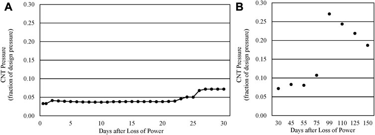
FIGURE 6. Containment pressure following loss of all power and no additional makeup water for (A) 0–30 days and (B) 30–150 days.
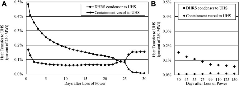
FIGURE 7. Heat transfer from the NPM (via DHRS and CNV) to the ultimate heat sink following loss of all power and no additional makeup water for (A) 0–30 days and (B) 30–150 days.
3 Protection against extreme events
The NuScale VOYGR power plant design incorporates seven layers of protection to ensure the highest standards of safety for people and planet (see Figure 8), including:
1. Oxide fuel pellet and cladding
2. Reactor vessel
3. Containment vessel
4. Reactor pool
5. Underground stainless steel lined concrete pool walls and floor
6. Biological shield
7. Seismic Category 1 building with HVAC filtration
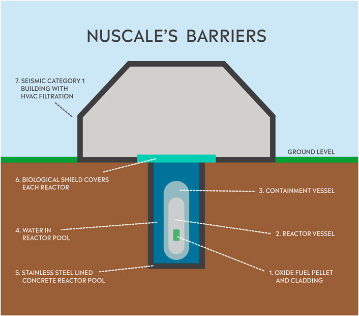
FIGURE 8. NuScale radiation and fission product barriers.
Nuclear power plants must be evaluated for seismic, high velocity winds and flooding events and already have significant resilience in these areas. Safety-related buildings are designed to Seismic Category 1 standards as demonstrated by comprehensive, site-specific seismic analyses. Several features of the NuScale reactor building make it more resilient to natural events. First, everything needed to assure a safe shutdown of the plant is housed within the Seismic Category 1 reactor building. During normal operation, all 6 NPMs reside within the reactor building ultimate heat sink which consists of a water-filled stainless steel lined concrete pool located below grade. Because of the reduced elevation of the reactor building and the embedded pool, the reactor building is able to be designed for 0.5 g horizontal and vertical zero period accelerations (ZPA) and peak accelerations of 1.1 g for frequencies from 3 to 12 Hz. This fact, in combination with the fully passive safety systems (i.e., no AC/DC power for safety) means that the NuScale reactor building is resilient to a Fukushima type event.
In island mode, the plant turbine generators independently provide power to onsite AC loads. Island mode is a non-safety and non-risk significant design feature that is not credited to meet regulatory or safety-related criteria. Following any loss of offsite power or the loss of the transmission system grid, our VOYGR plant can run in island mode, providing first responder power, and black start from cold conditions.
Several externally targeted events have also been considered in the VOYGR™ design. All US nuclear power plants are required to perform a design-specific assessment of the effects on the facility of the impact of a large, commercial aircraft as per NRC 50.150. Applicants are required to use realistic analyses to identify and incorporate into the design those design features and functional capabilities to show that, with reduced use of operator actions, the reactor core remains cooled, or the containment remains intact; and spent fuel cooling or spent fuel pool integrity is maintained. This provides the existing commercial fleet significant resiliency to aircraft impact. The NuScale reactor building has been designed to meet these requirements.
With regards to cyber security, NuScale is currently working with Brookhaven National Laboratory and the U.S. Department of Energy in an effort to develop a methodology to quantitatively assess the consequence of cyber-attacks on the safety, reliability, and availability of nuclear power plants. The NuScale plant has unique characteristics in this regard such that it does not rely on computer systems for assuring the safe shutdown and long-term cooling of the reactors. Furthermore, the NuScale module and plant protection systems are non-microprocessor systems (i.e., they use field programmable gate arrays). As a result, NuScale safety systems do not use software and are therefore not vulnerable to cyber-attacks.
With regards to resilience against geomagnetic storms and electro-magnetic pulse (EMP) events, NuScale commissioned a study with Oregon State University in collaboration with a team of EMP experts to identify features of the NuScale plant that provide inherent EMP protection (e.g., passive systems, below grade, compact footprint). The team was also tasked with identifying components/systems that may require additional attention to achieve higher levels of EMP hardness. A key feature in this regard is that following an EMP event, a NuScale plant has “black-start” and “island mode” capabilities to aid in grid recovery. That is, a NuScale plant can start up from cold conditions without external grid connections by using onsite back-up generators.
4 Licensing
The NuScale SMR is currently the only small modular reactor that has received design certification from the U.S. Nuclear Regulatory Commission (NRC). Figure 9 presents a flow chart that describes the NRC process for Standard Design Approval (SDA) and Design Certification under 10 CFR Part 52. The standard design approval (SDA) application is prepared by the vendor. Once approved, it is valid for 15 years. The Combined License (COL) is prepared by the customer and is required for construction and operations of each nuclear plant. The SDA is normally incorporated by reference into the COL. An Early Site Permit may be obtained in advance of a licensing proceeding and “banked,” or included in the COL application. The Design Certification is an additional step taken after obtaining an SDA which codifies the design into the Code of Federal Regulations (CFR). In the case of the NuScale 50 MWe design, the federal rule was issued as Appendix G to Title 10 CFR (United States Nuclear Regulatory Commission, 2023) Part 52.
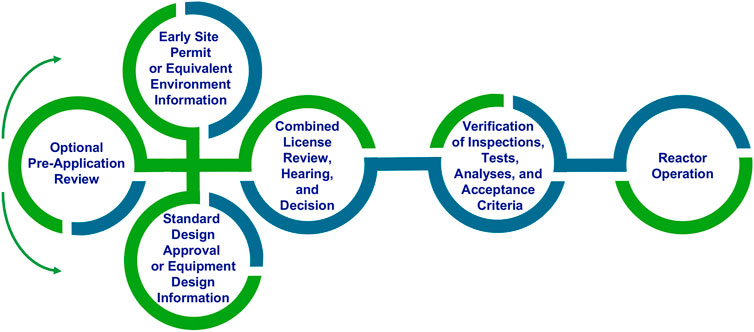
FIGURE 9. Flow chart of US NRC 10 CFR part 52 licensing process.
The NuScale Design Certification Application (DCA) was completed in December 2016. The review by the NRC commenced in March 2017. NuScale received standard design approval in September 2020 and design certification in January 2023 for its 50 MWe NPM configured as a 12 module plant. The DCA consisted of 12,000 pages of design information; requiring 2 million labor hours to prepare. It involved in excess of 50 suppliers and partners and approximately 800 people. The total expenditure to complete the design effort leading to DCA submittal was ∼$500M. The NRC review of the DCA was completed in 41 months, 1 month ahead of schedule. The review required an additional 2 million pages of Supporting Material and test data at a cost of $70M in NRC fees and $200M of in-house costs.
Because of its unique safety, the NuScale design has received many “first-of-a-kind” approvals from the NRC, including.
• No connection to the AC transmission grid required for safety. Regulations permits “off-grid” operation - A very important feature for providing reliable power and process heat to industrial applications.
• NRC approved control room staffing. Three operators can safely operate 12 reactors in a single control room
• Elimination of Shift Technical Advisor (STA) position
• Use of unique cyber resistant FPGA based Module Protection and Plant Protection Systems.
• Approval of the NuScale Emergency Planning Zone (EPZ) sizing methodology. As opposed to a 10 mile radius EPZ, a site boundary EPZ is achievable for a NuScale plant at most US sites surveyed.
NuScale is currently seeking standard design approval to increase its core power to 250 MWt, nominally 77 MWe per module, in a 6-module plant (VOYGR™-6) configuration. The SDA application and topical reports were received by the NRC in January 2023. NRC review of the uprated NPM is expected to take 24 months.
5 Conclusion
NuScale’s SMR technology has features, capability, and performance not found in current nuclear power facilities. It offers a fully passive safety system design, demonstrated by the NuScale Triple Crown for Nuclear Plant Safety™ which ensures that reactors will safely shut down and self-cool for an unlimited amount of time, and do so with no need for operator or computer action, AC or DC power, or the addition of water.
The high-level safety of NuScale’s SMR technology is foundational to a new standard of nuclear power plant resilience. The NuScale VOYGR power plant is resilient to earthquakes, geomagnetic disturbance, and other natural events, as well as to electromagnetic pulse events or aircraft impact. The module and plant protection systems are non-microprocessor-based and use field programmable gate array technology that is invulnerable to cyber-attacks. A NuScale VOYGR plant does not need to be connected to the main grid for safety. In fact, following any loss of offsite power or the loss of the transmission system grid, our VOYGR plant can run in island mode, providing first responder power. The NuScale VOYGR plant can be located at the “end of the line” or off-grid, without the requirement for offsite transmission source(s) to the station.
Data availability statement
The original contributions presented in the study are included in the article/Supplementary Material, further inquiries can be directed to the corresponding author.
Author contributions
All authors listed have made a substantial, direct, and intellectual contribution to the work and approved it for publication.
Funding
This material is based upon work supported by the Department of Energy under Award Number DE-NE0008928. This presentation was prepared as an account of work sponsored by an agency of the United States (U.S.) Government. Neither the U.S. Government nor any agency thereof, nor any of their employees, makes any warranty, express or implied, or assumes any legal liability or responsibility for the accuracy, completeness, or usefulness of any information, apparatus, product, or process disclosed, or represents that its use would not infringe privately owned rights. Reference herein to any specific commercial product, process, or service by trade name, trademark, manufacturer, or otherwise does not necessarily constitute or imply its endorsement, recommendation, or favoring by the U.S. Government or any agency thereof. The views and opinions of authors expressed herein do not necessarily state or reflect those of the U.S. Government or any agency thereof.
Conflict of interest
KW, AB, and JR are employed by NuScale Power.
Publisher’s Note
All claims expressed in this article are solely those of the authors and do not necessarily represent those of their affiliated organizations, or those of the publisher, the editors and the reviewers. Any product that may be evaluated in this article, or claim that may be made by its manufacturer, is not guaranteed or endorsed by the publisher.
References
Keywords: small modular reactor (SMR), defense in depth (DiD), passive safety, design certification, light water cooled reactors
Citation: Welter K, Reyes JN Jr and Brigantic A (2023) Unique safety features and licensing requirements of the NuScale small modular reactor. Front. Energy Res. 11:1160150. doi: 10.3389/fenrg.2023.1160150
Received: 06 February 2023; Accepted: 29 March 2023;
Published: 17 April 2023.
Edited by:
Marcus Seidl, PreussenElektra GmbH, GermanyReviewed by:
John Darrell Bess, JFoster & Associates, LLC (JFA), United StatesRyan Meyer, Pacific Northwest National Laboratory (DOE), United States
Copyright © 2023 Welter, Reyes and Brigantic. This is an open-access article distributed under the terms of the Creative Commons Attribution License (CC BY). The use, distribution or reproduction in other forums is permitted, provided the original author(s) and the copyright owner(s) are credited and that the original publication in this journal is cited, in accordance with accepted academic practice. No use, distribution or reproduction is permitted which does not comply with these terms.
*Correspondence: Kent Welter, S1dlbHRlckBOdVNjYWxlUG93ZXIuY29t
†These authors have contributed equally to this work and share first authorship