 Arianna Gea Pagano
 Gráinne El Mountassir
95% of researchers rate our articles as excellent or good
Learn more about the work of our research integrity team to safeguard the quality of each article we publish.
Find out more
ORIGINAL RESEARCH article
Front. Energy Res. , 04 April 2023
Sec. Nuclear Energy
Volume 11 - 2023 | https://doi.org/10.3389/fenrg.2023.1156301
Hazardous nuclear waste is produced at all stages during the nuclear fuel cycle. The removal operations of nuclear waste from nuclear reactors and/or storage facilities, such as spent fuel pools and storage silos, pose a hazard for the workforce and the environment, due to the potential release of radioactive particulates, and loss of radioactive debris. The development of innovative techniques to address this issue is desirable. A potential technology to inhibit particulate release during nuclear waste removal and transport operations is colloidal silica grouting. Colloidal silica is an aqueous suspension of silica (SiO2) nanoparticles, able to provide immobilisation of particulates within a hydrogel matrix. In this study, an experimental investigation was carried out to simulate colloidal silica grouting operations around objects at temperatures of 60°C and 120°C, to simulate radioactive waste in standard storage conditions, and during loss of cooling/loss of coolant accident scenarios. The results of the experimental campaign confirm the suitability of colloidal silica to safely remove and transport heat-generating radioactive waste. Critical parameters for designing the silica grout mix, in order to optimise the performance of the hydrogel upon exposure to temperature in different scenarios, are identified and discussed.
Nuclear power plants around the world provide 10% of the world’s electricity from about 440 reactors. The nuclear fuel cycle, i.e., the process of using nuclear materials for electricity production, is the second largest source of low-carbon power (World Nuclear Association, 2021).
At all stages of the nuclear fuel cycle, radioactive waste is produced. This may be in the form of irradiated fuel bundles removed from commercial nuclear reactors (spent fuel), or by-products of fuel fabrication and usage, containing radionuclides. Radioactive waste must be appropriately managed depending on the content of long-lived radionuclides, in order to prevent their release into the biosphere (NEA & OECD, 2020).
Interim storage is a temporary measure to safely allow radiation and heat decay of high-level radioactive waste prior to long-term disposal. Storage is often carried out in wet silos, in at-reactor ponds, or in common pools at centralised facilities, where water is continuously circulated to provide radiation shielding and cooling. The maximum temperature of the cooling water (and, hence, of the waste) is normally kept below 40°C–60°C, depending on the type of storage facility (Vitkova, et al., 2006). In extreme scenarios (e.g. loss of cooling/loss of coolant accidents), the radioactive waste may be found at significantly higher temperatures, exceeding 100°C (Karyakin et al., 2019).
All operations requiring the handling and transport of radioactive waste pose a hazard in terms of radiation exposure for the workforce and the environment. Such operations include transport from the nuclear reactor to interim storage, from at-reactor ponds to common pools, and upon removal from common pools and wet storage silos to longer-term dry storage or disposal sites. During these operations, the loss of radioactive debris and accidental release of hazardous radioactive particulates may occur, due to waste corrosion and cladding degradation mechanisms that occur during storage (including oxidation, stress corrosion cracking, hydrogen effects and mechanical degradation (NEA & OECD, 2020). The development of techniques to inhibit particle loss during the handling and transport of radioactive waste at 40°C–60°C (standard storage conditions) or at higher temperatures (>100°C, after loss of cooling/loss of coolant accidents) could significantly reduce the associated hazard for the workforce and the environment.
Previous research has demonstrated that air-borne and water-borne particle loss can be inhibited in soils and rocks during tunnelling operations by injecting colloidal silica-based grouts (Bahadur, et al., 2007; Butrón, et al., 2010). Colloidal silica (CS) is an aqueous suspension of silica (SiO2) nano-sized particles, with low initial viscosity (∼10 mPa s) and excellent penetrability into fractured and porous/particulate media. For grouting purposes, the CS suspension is mixed with an electrolyte solution (prior to injection) to induce a gelation process, i.e. the gradual transition from a liquid colloidal suspension to a solid water-saturated gel (hydrogel), able to seal fractured materials and to embed loose particulates. Unlike cementitious grouts already in use for nuclear waste immobilisation (both conventional and novel high-penetration grouts, Varlakov and Zherebtsov, 2021), CS hydrogels can be easily excavated without producing fine particulates. CS hydrogels can also provide radiation shielding thanks to their high water content (typically >60% by mass), and have been shown to enhance the immobilisation capacity of radioactively contaminated soils and waste materials (Bots, et al., 2020). These properties are all desirable for a technology to reduce hazard in the removal and transportation of hot radioactive material. In addition, CS hydrogel contains glass-forming agents, namely silica (as the basic grout component), and sodium (from the electrolyte accelerator), making it an excellent material for subsequent immobilisation via vitrification (i.e., the current preferred approach for the permanent immobilisation of intermediate- and high-level radioactive waste, Gin, et al., 2017).
To use CS for grouting heat-generating wastes, the effects of elevated temperature on grout behaviour must be investigated. Previous research has mainly focused on the effect of elevated temperature on the speed of gelation, showing a reduction in gel time with increasing temperature (Hunt, et al., 2013; Pagano, et al., 2021). Hunt et al. also observed good thermal stability of gelled CS samples stored at 200°C for up to 2 weeks, while gel decomposition (solid/water separation) occurred within 72 h when samples were stored at 300°C. Evidence of the effect of encapsulating hot objects within the hydrogel’s matrix is currently lacking.
This study provides a proof of concept for deploying CS grouting to temporarily encapsulate hot radioactive waste and spent fuel prior to removal and transportation, with the aim of minimising particulate release during retrieval operations (Figure 1). In a first stage, mechanical tests were carried out to assess the effect of temperature, curing time and silica concentration on the strength properties of the gel under two loading modes: i) tensile loading to simulate temperature-induced crack initiation, and ii) shearing to simulate damage during handling/transport. The water retention characteristics of the hydrogel were also determined to assess the effect of silica concentration on the gel’s porosity, giving a qualitative indication of the gel’s gas permeability. In a second stage, experiments simulating CS grouting around objects at temperatures of 60°C and 120°C were carried out, to simulate standard storage conditions and accident scenarios, respectively. The performance of the gel was assessed by means of X-ray imaging to detect the presence and spatial distribution of temperature-induced cracks. The parameters affecting temperature-induced cracking and integrity upon handling are discussed, and guidance is provided to optimise the grout mix to improve its performance.
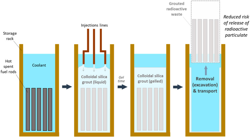
FIGURE 1. Example of pre-treatment of radioactive waste (in standard storage conditions) with colloidal silica grout, prior to removal and transport.
CS suspension MasterRoc® MP320 Part A, supplied by Master Builders Solutions (MBCC Group), was used in this study as the basic component of all grout mixes. The properties of the suspension as provided by the manufacturer are: viscosity (at 20°C) ∼10 mPas; density (at 20°C) = 1.3 kg/L; silica concentration by mass = 40 ± 1%; pH = 9.5 to 9.8. Sodium chloride (NaCl) solutions were used as the electrolyte accelerator to induce grout gelation.
Two grout mixes were tested in this study. In one grout mix (Grout 1), as-delivered MP320 Part A was mixed with a 2.5 M NaCl solution, at a 5:1 CS:accelerator ratio by volume. In the other grout mix (Grout 2), the silica concentration was halved by diluting the as-delivered MP320 Part A with de-ionised water at a 1:1 CS:water ratio by mass. Then, the diluted CS suspension was mixed with a 4.2 M NaCl solution, at a 5:1 CS:accelerator ratio by volume. The resulting silica concentrations by mass of Grout 1 and Grout 2 were wt% = 34 and 17, respectively. Grout mixes were prepared at room temperature (20°C ± 1°C) throughout this study. The molarities of the NaCl accelerators were selected to ensure a gel time of ∼10 min at 20°C for both Grout 1 and Grout 2, i.e., the time corresponding to a sudden increase of gel’s viscosity overtime, defined as the intersection between the linear regression of all points at viscosity higher than 2000 mPa s in a time-versus-viscosity graph (Bergna and Roberts, 2005).
Mechanical tests were carried out to explore the stress-strain behaviour of CS gel upon different loading modes, at varying silica concentrations (wt% 34 and 17, as discussed in Section 2.1) and curing temperatures. The curing temperature is defined here as the temperature of the grout during gelation and storage, prior to mechanical testing. Three curing temperatures of 20°C (ambient), 40°C and 60°C were selected. A summary of all mechanical tests performed in this study is reported in Tables 1–3.

TABLE 1. Summary of splitting tensile (ST) tests for tensile strength determination.
Two types of mechanical tests were carried out:
1. Tensile strength tests. Temperature-induced cracking in CS gel can be induced by the development of tensile stresses, resulting from the formation of air pockets or water vapour within the hydrogel upon temperature exposure. To assess the proneness of the gel to temperature-induced cracking, Brazilian-type splitting tensile tests were carried out in a loading frame apparatus (Figure 2), equipped with a 50 kN load cell, on cylindrical cores (37 mm diameter, 75 mm length). Tests were performed according to BS EN 12390-6:2009, except for the core diameter (37 mm instead of ≥100 mm; the recommended length-to-diameter ratio of 2 was used in this study), and the control mode (displacement control of 0.1 mm/min instead of stress control). Silica gel cores (‘CS gel’, Table 1) and 2-mm diameter glass bead cores grouted with CS (‘CS gel + glass beads’, Table 1) at different silica concentrations (wt% 34 and 17) were tested in this study. All cores were created within bespoke silicone rubber moulds and left to cure for 24 h prior to demoulding and testing. Grouted glass bead cores were obtained by injecting CS grout under gravity through flexible tubing connected to the bottom of the moulds, previously filled with glass beads. Curing was carried out for 24 h either at room temperature (20°C), or within a water bath (at 40°C or 60°C) to assess the effect of temperature on the tensile strength. Water evaporation from the moulds was prevented throughout curing using cling film to avoid evaporation cracks.
2. Shear strength tests. The shear strength characteristics of CS gel are relevant to assessing the ability to maintain its integrity upon retrieval and transport, without inducing shear failure. Two types of shear tests were performed in this study:
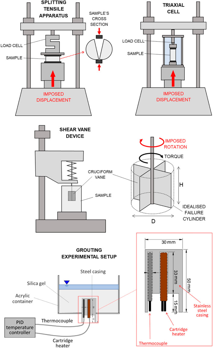
FIGURE 2. Schematic view of the experimental setups for splitting tensile testing, triaxial testing, shear vane testing, and grouting experiments.
a) Shear vane tests on silica gel only: the undrained shear strength of silica gel was assessed using a Wykeham Farrance shear vane device (Figure 2), equipped with a H = 12.7 × D = 12.7 mm cruciform vane with constant rotational speed (6–12 degrees per minute). Silica gel specimens at silica concentrations of wt% 34 and 17 were created and tested within glass containers with hexagonal cross section, to avoid slippage of the gel along the container’s walls during testing. Six series of tests were performed to assess the evolution of the undrained shear strength over time (up to 6 days, with additional data at 4.5 months for selected specimens), at different curing temperatures (20°C, 40°C, and 60°C—for 40°C and 60°C temperature was maintained with the aid of a water bath), as reported in Table 2. The undrained shear strength,
where
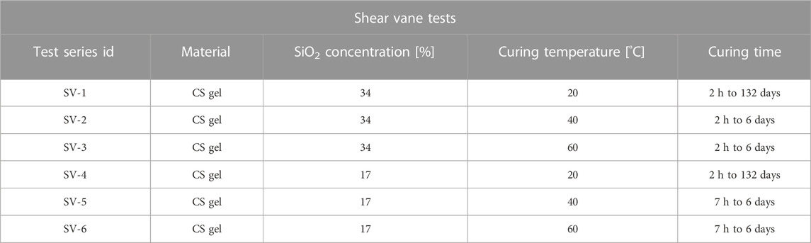
TABLE 2. Summary of shear vane (SV) tests for undrained shear strength determination. Each test series includes specimens from the same grout batch, tested at different times after grout mixing (curing time).
b) Unconsolidated Undrained (UU) triaxial tests on CS grouted glass beads: an ELE triaxial test apparatus (Figure 2) was used to determine the undrained strength of grouted glass bead cylindrical cores (37 mm diameter, 75 mm height. The use of the shear vane device on the CS grouted glass beads specimens was not possible due to the coarse texture of the specimens). All tests were performed at 300 kPa cell pressure, and 0.032 mm/min strain rate. Similar to the tensile tests, cores for triaxial testing were created at different silica concentrations (wt% 34 and 17) within silicone rubber moulds, and cured for 24 h at 20°C, 40°C or 60°C (Table 3). The deviator stress,
where
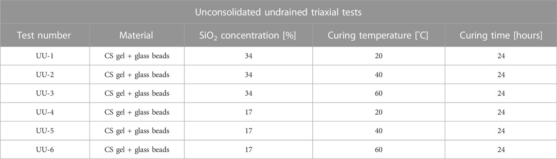
TABLE 3. Summary of Unconsolidated Undrained (UU) triaxial tests for undrained shear strength determination.
The water retention properties of two CS gel samples at silica concentrations wt% 34 and 17 were explored to determine their air entry value (AEV), defined as the matric water potential (negative pore water pressure due to adsorptive forces) at which air first enters the largest pores during desaturation. Each gel sample was prepared by pouring 7 ml of CS grout into a stainless steel cup (37.4 mm diameter), and was allowed to air-dry under laboratory conditions at 20°C. The sample’s mass, volume and total water potential were measured at different stages upon drying to derive the gel’s water retention curve.
The total mass (
where
The total water potential,
where
To explore the effect of exposing CS gel to temperatures higher than ambient (e.g. when grouting a hot object such as a fuel assembly or other heat-generating waste materials), an experimental setup was designed to allow CS grouting around a temperature-controlled metallic object. A schematic view of the experimental setup is shown in Figure 2.
The setup consisted of: a) a transparent acrylic cylindrical container (115 mm inner diameter), designed to host the grout; and b) a stainless-steel cylinder (30 mm diameter, 50 mm height) enclosing a thermocouple and a resistive cartridge heater, both connected to a Proportional Integral Derivative (PID) temperature controller to allow ramping to and maintenance of the selected target temperature.
Grouting experiments were designed to evaluate the effect of different variables potentially affecting the performance of the grout. The experimental conditions for each experiment are summarised in Table 4. The following variables were explored:
1. Temperature of the grouted object: two testing temperatures were selected in this study: a) 60°C, i.e. the maximum water temperature allowed during standard storage; and b) 120°C, simulating loss of cooling/loss of coolant accident conditions.
2. Grouting conditions: CS grout was gelled either during heating or prior to heat exposure, as schematically shown in Figure 3:
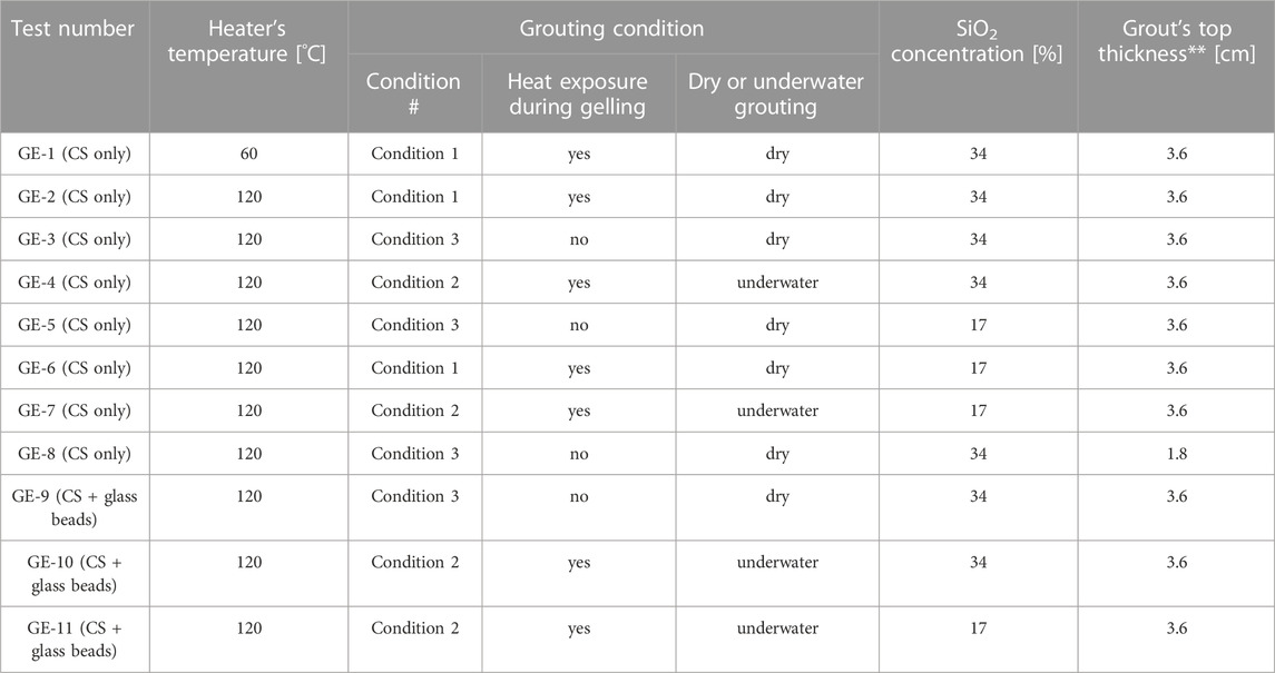
TABLE 4. Summary of grouting experiments (GE). **The top thickness of the grout is intended as the distance between the top of the heater and the top surface of the grouted volume.
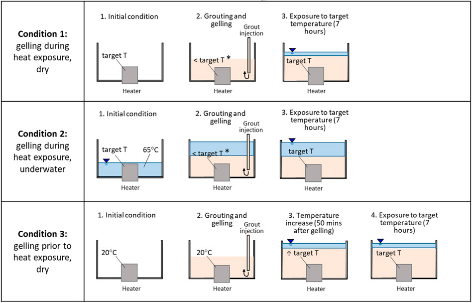
FIGURE 3. Schematic representation of grouting conditions. (*Temporary cooling of the heater due to injection of grout at room temperature).
A set of experiments was performed by first heating up the steel casing (simulating hot radioactive waste) to the target temperature, and then by injecting the ungelled grout by gravity at the bottom of the acrylic cylinder (gelling during heat exposure, Figure 3). Grout injection was carried out in the absence of water in the acrylic cylinder (referred to as ‘dry’ grouting in Table 4), to simulate grouting operations of radioactive waste stored dry, or during loss of coolant accidents. After gelation, the grout surface was covered with a thin layer of water to prevent evaporation cracks.
As in condition 1, the grout was exposed to heat during gelling. However, the acrylic cylinder was first filled with water at 65°C, and then the ungelled grout was injected underwater at the bottom of the acrylic cylinder, to simulate grouting operations of radioactive waste stored underwater (‘underwater’ grouting, Table 4; Figure 3). The injection was carried out slowly to allow the upwards displacement of water while avoiding turbulent mixing with the grout.
In practice under realistic grouting conditions, the ungelled grout would initially cool the waste (unless injected at the same temperature as the waste). Hence, grout gelation could occur before the temperature of the waste stabilises, after the initial cooling. To simulate this, a set of experiments were carried out by injecting the grout with the heating element set at room temperature (in the absence of water), and then by ramping up the heater’s temperature to a target value, 50 min after grout gelation (gelling prior to heat exposure, Table 4; Figure 3). Surface evaporation from the grout was prevented by placing a thin layer of water above the grout after gelation.
3. Silica concentration: the effect of the concentration of silica nanoparticles was explored by carrying out experiments with grout mixes at silica concentrations of wt% 34 and 17, as described in Section 2.1.
4. Grout thickness: most grouting experiments were carried out by submerging the heater with grout up to 3.6 cm above its top surface. The effect of reducing the grout thickness was explored by halving the thickness of the layer of grout above the heater (from 3.6 to 1.8 cm).
5. Grouted medium: the presence of radioactive waste in the form of hot rubble was simulated by filling the acrylic container with 2-mm diameter glass beads prior to grouting. This created a hot porous medium, grouted by gravity-driven injection from the bottom of the setup.
In all experiments, the temperature of the heater was maintained constant for 7 h after reaching its target value. The appearance of lateral and surface cracks was visually monitored, prior to carrying out X-ray microstructural analyses (described in the next section). The gel was then extruded from the acrylic cylinder at the end of each experiment to qualitatively assess its integrity upon removal i.e. the ability to handle the grouted ‘waste’ without causing failure (e.g. along temperature-induced cracks/weak points) or being subject to excessive deformation.
At the end of each grouting experiment, the experimental setup was left to cool down to room temperature and transferred to a Nikon XTH320 micro-CT scanner to image the internal three-dimensional structure of the gel. Scans were performed at 100 kV energy and 110 μA current, with a voxel size of 66 × 66 × 66 μm. Nikon software CT Pro 3D was used for the 3D image reconstruction (edge effects were minimised by applying a beam hardening correction). Avizo 9.3 software was used for processing the reconstructed volumes. The X-CT data within 1 cm from the bottom of the acrylic cylinder were discarded to remove image artefacts, and a median filter was applied to reduce noise. The multiphase watershed segmentation tool implemented in Avizo was used to identify the different phases within the imaged volume - namely silica, water, and air. The resulting 3D images allowed identification of the geometry and spatial distribution of cracks and voids.
The splitting tensile tests carried out in this study give an insight into the stress-strain behaviour of the material upon tensile loading, thus helping assess the proneness of the gel to temperature-induced cracking. The results of splitting tensile tests ST-1 and ST-2 are compared in Figure 4 to explore the effect of silica concentration (wt% 34 and 17, respectively) on the tensile strength of silica gel, after 24-h curing at 60°C. As expected, ST-1 exhibited a higher tensile strength than ST-2 (6.6 and 1.5 kPa respectively), due to the higher silica concentration and, hence, larger amount of siloxane bonds formed during gelation. ST-1 also exhibits a stiffer response upon loading, i.e. a steeper gradient in the plot of tensile stress against vertical displacement (Figure 4). By contrast, the gel in ST-2 underwent larger deformation upon loading before reaching its tensile strength (maximum vertical displacement: 0.8 mm in ST-1, 1.2 mm in ST-2, Figure 4).
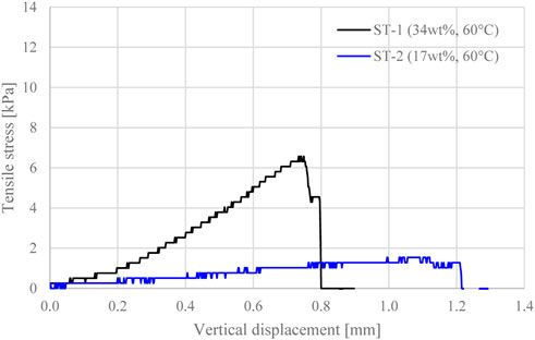
FIGURE 4. Tensile stress evolution with vertical displacement for gel samples cured for 24 h at 60°C, at silica concentration wt% 34 and wt% 17.
The effect of different curing temperatures (20, 40°C and 60°C) on the tensile strength at silica concentrations of wt% 34 and 17 was also assessed (tests ST-3 to ST-8, Figures 5A, B). Here, silica-grouted glass bead cores were tested, as the tensile strength of the CS gel only, cured at temperatures lower than 60°C, was too low to be detected accurately via splitting tests. The tensile strength of the CS-grouted beads is qualitatively representative of the tensile strength of the gel, as tensile failure occurred within the gel matrix, around the glass beads (inter-granular failure). As shown in Figure 5, the tensile strength and the rate of stress gain upon vertical displacement were directly proportional to the curing temperature, at both silica concentrations. By increasing the curing temperature from 20°C to 60°C, the tensile strength increased from 11.9 to 27.1 kPa at wt% 34 (Figure 5A), and from 1.3 to 5.2 kPa at wt% 17 (Figure 5B). Similar to the silica gel specimens, all CS-grouted glass bead specimens at wt% 17 exhibited a higher vertical displacement at failure (and, hence, higher ability to accommodate deformation) when compared to wt% 34, cured at the same temperature.
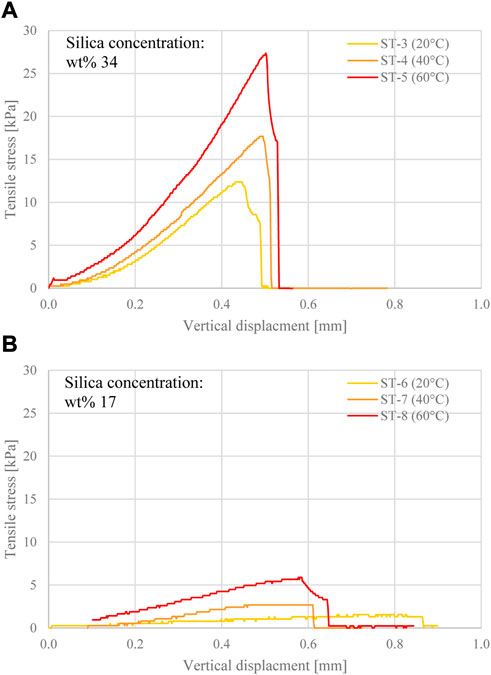
FIGURE 5. Tensile stress evolution with vertical displacement for grouted glass bead cores cured for 24 h at different temperatures, at silica concentration (A) wt% 34, and (B) wt% 17.
The undrained shear strength of the hydrogel was determined via shear vane tests (the term “undrained” indicates that the rate of shearing was faster than the ability of water to drain from the specimen). The effect of silica concentration (wt% 34 and 17) and curing temperature (20°C, 40°C, and 60°C) were explored. Furthermore, the evolution of the undrained shear strength against curing time was assessed.
The results of all shear vane tests in terms of the evolution of the undrained shear strength over time are shown in Figures 6A, B. Data points belonging to the same curve correspond to specimens taken from the same grout batch, tested at different times after grout mixing (i.e. different curing times). Curing times ranged from 2 h to 132 days (∼4.5 months) at a curing temperature of 20°C, and from 2 h to 6 days at 40°C and 60°C. Specimens at silica concentration wt% 34 (Figure 6A) exhibited a higher undrained shear strength than those at wt% 17 (Figure 6B), due to the higher density of siloxane bonds. This is consistent with previous research by Persoff, et al. (1999) and Gallagher and Mitchell (2002), where increasing the silica concentration of the grout was observed to increase the unconfined compressive strength of grouted sand specimens. It is worth noting that halving the silica concentration from 34% to 17% reduced the undrained shear strength by a factor of 10, irrespective of the curing time and the temperature.
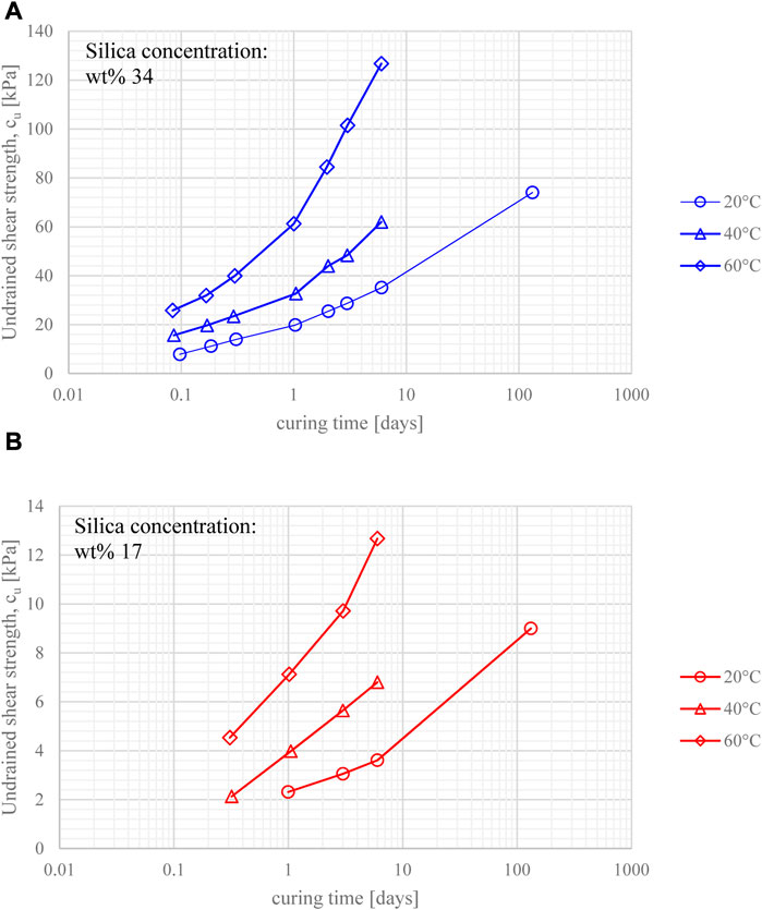
FIGURE 6. Undrained shear strength evolution against curing time for gel samples cured at different temperatures, at silica concentration (A) wt% 34, and (B) wt% 17.
All gels showed a significant strength increase within the first few hours, with similar strength gain overtime (e.g., strength values went up by ∼60% from 1 to 6 days for all samples, irrespective of silica concentration and curing temperature). The strengthening of the gel was observed to slow over time, however it did not reach a plateau (note that curing time is plotted on a log scale in Figure 6). Furthermore, the undrained shear strength exhibited a non-linear increase with curing temperature; this is also shown in Figures 7A, B. It is unclear whether the effect of curing temperature on the values of strength obtained for the same curing time, is due only to the difference in strength gain rate (which increases with temperature), or is also due to the influence of temperature on the strength of the siloxane bonds formed.
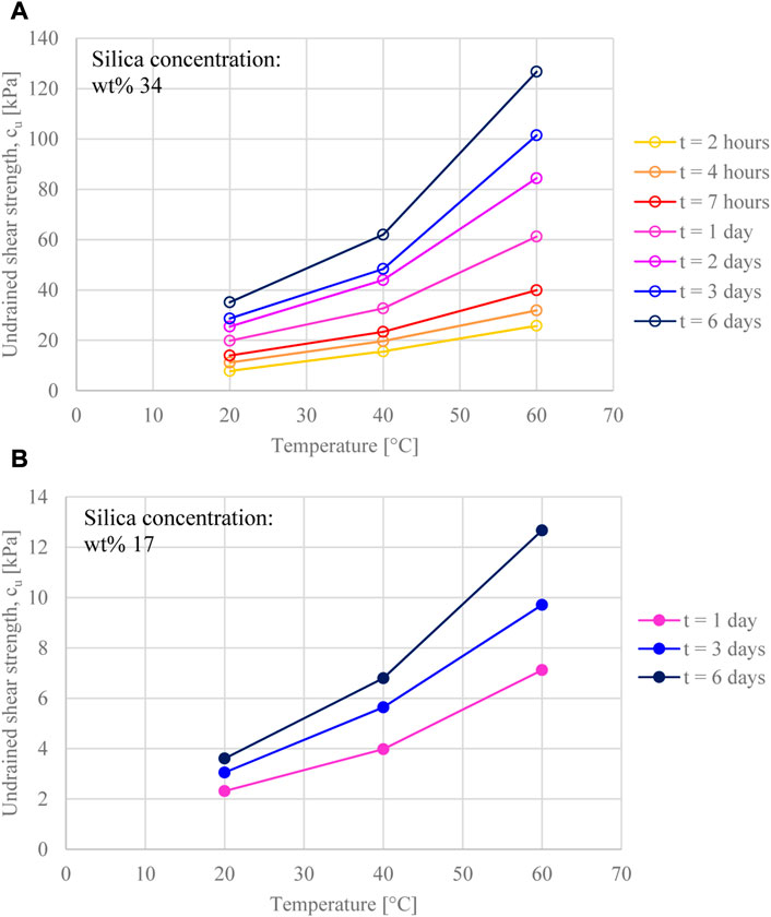
FIGURE 7. Undrained shear strength evolution against temperature at different curing time, for gel samples at silica concentration (A) wt% 34, and (B) wt% 17.
The undrained shear strength of grouted glass bead cores was determined via Unconsolidated Undrained (UU) triaxial tests, at different silica concentrations (wt% 34 and 17) and curing temperatures (20°C, 40°C and 60°C). The results of all UU tests are shown in Figures 8A, B.
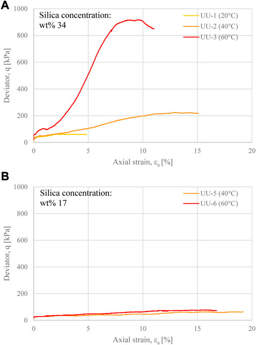
FIGURE 8. Deviator stress evolution with axial strain for grouted glass beads samples cured for 24 h at different temperatures, at silica concentration (A) wt% 34, and (B) wt% 17.
The influence of silica concentration and curing temperature on the stress-strain behaviour of grouted glass bead cores was comparable to that observed upon tensile testing. All cores exhibited a strength increase with increasing curing temperature. This was extremely significant for cores at wt% 34 (Figure 8A), with peak shear strength values ranging from 59.3 kPa (at 20°C curing temperature), to 913.9 kPa (at 60°C curing temperature). At wt% 17, the shear strength of core UU-4, cured at 20°C, was not accurately measurable due to the inability to set up the core for triaxial testing without causing disturbance to the specimen. The remaining cores at wt% 17, cured at 40°C and 60°C, reached peak shear strength values of 61.7and 76.7 kPa respectively (Figure 8B). The relatively small difference between these values suggests that the majority of the strength at low silica concentration is associated with the frictional resistance between the glass beads, rather than the shear properties of the gel matrix.
The stress-strain behaviour upon shearing was significantly affected by both curing temperature and silica concentration. At wt% 34 the cores exhibited an increasingly brittle behaviour with increasing temperature, i.e. a stress increase upon axial displacement prior to failure proportional to the curing temperature, followed by strain-softening in UU-3. Also, all cores UU-1 to UU-3 exhibited a clear shear band at failure. In comparison, cores at wt% 17 (UU-5 and UU-6) exhibited more ductile behaviour, with significantly lower stress gain with increasing axial strain, higher deformability prior to failure, and a barrelling failure mode. These observations are in line with both the tensile and shear vane results.
Figure 9 shows the evolution of the degree of saturation,
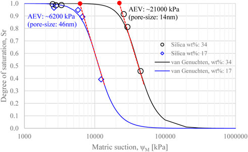
FIGURE 9. Water retention curves of CS gel samples at silica concentration wt% 34 and wt% 17.
The AEV is controlled by the size of the largest pores of the porous medium, through which desaturation is initiated. An estimate of the order of magnitude of the pore-size corresponding to a pressure equal to the AEV can be obtained from Washburn equation, as:
where
The results of the grouting experiments GE-1 and GE-2 (Table 4) can be compared to assess the effect of temperature on silica gel cracking. Both experiments were carried out using a grout mix of wt% = 34, which was mixed at room temperature and injected around the heater at 60°C in GE-1 and 120°C in GE-2. Initial cooling of the heater was observed upon grouting, down to ∼30°C in GE-1, ∼60°C in GE-2. Temperature targets (60°C and 120°C) were reached again within 8–10 min. The images reconstructed from X-ray tomography scans in Figure 10 show a vertical cross-section passing through the centre of the grouted heater at the end of experiments GE-1 and GE-2. Note that all X-ray tomography results shown hereafter are reported as similar 2D cross sections, which do not fully capture the features of the 3D reconstructed volumes. Please refer to the Supplementary Material to access the 3D visualisation of the reconstructed volumes.
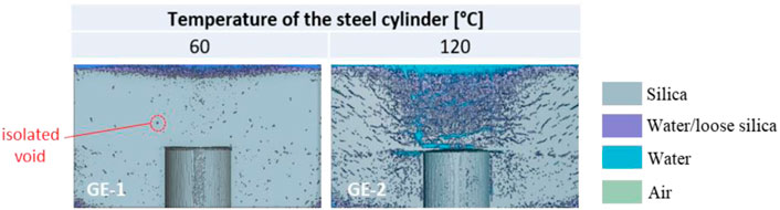
FIGURE 10. Vertical cross-section passing through the centre of the 3D reconstructed volume obtained via X-ray tomography, at the end of GE-1 and GE-2. Please refer to the supplementary material to access the 3D visualisation of the reconstructed volumes.
In GE-1, unconnected crevices were observed to appear at the outer lateral surface of the gelled cylinder ∼2 h after grouting; these did not propagate further over the duration of the experiment (7 h). This was confirmed via X-ray scanning (Figure 10, left), where isolated, mm-sized voids were detected throughout the gel at the end of the experiment. These are believed to be associated with the de-aeration of the aqueous phase of the grout mix upon heating, as further discussed in Section 4. Upon extrusion from the acrylic cylinder, the gel remained intact (as a whole) and easy to handle (i.e. no crumbling, large deformation or loss of material), thus confirming the potential of CS grouting around waste at 60°C.
Exposing the gel to 120°C in GE-2 had a greater effect on the gel’s integrity. Here, a crack appeared at the top surface as soon as the heater reached 100°C, about 10 min after initial cooling. From this point on, continuous water vapour release from the surface crack was observed, together with the formation of horizontal cracks at the lateral surface of the gelled cylinder, which appeared ∼2 h after grouting. Upon X-ray scanning, all cracks were found to originate from the heater, and propagated radially outwards to accommodate water vapour release (Figure 10, right). In addition, the volume of silica just above the heater was detected to be slightly looser than the surrounding gel, with an X-ray density comparable to that of the silica particle suspension that fills voids/cracks (referred to as ‘water/loose silica’ in Figure 10). The loose silica is assumed to be related to the upward migration of water vapour, not only through open cracks, but also through the gel’s porosity above the heating element, where the temperature gradient is highest. Despite the presence of cracks, the gel maintained its overall integrity upon extrusion.
The effect of grouting conditions on gel cracking can be explored by comparing the results of experiment GE-2 described in the previous section (Grouting condition 1: gelling during heat exposure, dry), with GE-3 (Grouting condition 3: gelling prior to heat exposure, dry) and GE-4 (Grouting condition 2: gelling during heat exposure, underwater). In all three experiments, grout mixes of wt% = 34 were used, and the target temperature of the heater was set to 120°C. The results of the X-ray tomographies at the end of GE-2, GE-3, and GE-4 are shown in Figure 11 (top row).
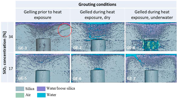
FIGURE 11. Vertical cross-section passing through the centre of the 3D reconstructed volume obtained via X-ray tomography, at the end of GE-2 to GE-7. Please refer to the supplementary material to access the 3D visualisation of the reconstructed volumes.
In GE-3, the grout was gelled at ambient temperature, and the heater was switched on 50 min after gelation. A horizontal lateral crack appeared ∼4 cm below the top surface of the gel, ∼10 min after 120°C was reached (i.e., 20 min after reaching 100°C). The crack propagated, widened (up to ∼3 mm width) and joined the top surface, where continuous water vapour release was observed thereafter. This crack was detected via X-ray CT scanning (circled in Figure 11, top left). Similar to GE-2, several other fissures originated from the heater and propagated outwards through the gel. By comparison to GE-2, the distribution of cracks in GE-3 was characterised by fewer, but larger, connected cracks, potentially indicating a poorer performance upon retrieval. This is likely to be due to the longer curing time before exposure of the gel to 120°C in GE-3, corresponding to a more limited ability to accommodate deformation upon tensile loading (as further discussed in Section 4). At the end of GE-3 the gel remained intact upon extrusion, however a wide crack cutting through the gel from the lateral boundary to the top surface (see 3D visualisation in the supplementary information) represents a significant weak point, making the gel more prone to breakage upon handling.
In GE-4, the presence of water during grouting seemed to mitigate the formation of cracks. After an initial cooling down to ∼55°C when the grout was injected underwater at room temperature, the heating element stabilised at 120°C after 15 min. The interface between the silica gel and the water (at the top of the gelled cylinder) was characterised by a layer of suspended silica particles/ungelled silica, ∼ 1–2 cm thick, where water vapour release was observed without the formation of visible cracks. Some lateral fissures still appeared at the outer boundary of the gelled silica, similar to GE-2 and GE-3, but these were visually observed to be thinner and less frequent. The X-ray microstructural analysis confirmed the presence of thin fissures throughout the gel, less frequent and poorly connected compared to GE-2 and GE-3. The X-ray analysis also showed the presence of large air- and water-filled voids around the heater, up to ∼0.5 cm wide. However, these large voids did not develop into large connected cracks and therefore they did not undermine the overall integrity of the gel, which remained whole and easy to handle upon extrusion.
The effect of the concentration of silica nanoparticles in the grout was assessed by performing a set of three experiments, namely GE-5, GE-6, and GE-7. Here, experimental conditions were identical to GE-3, GE-2, and GE-4 respectively, expect for the use of a diluted grout mix (wt% = 17). The results of the X-ray tomographies of the central vertical cross-sections at the end of each experiment are shown in Figure 11 (bottom row).
Halving the silica concentration had a beneficial effect on the extent of cracking in all experiments, in terms of both frequency and width of cracks formed. In GE-5, connected cracks were still observed upon visual inspection and X-ray CT scanning, however these were thinner and less frequent when compared with GE-3 at double the silica concentration. Both GE-6 and GE-7 were characterised by only one localised opening reaching the top of the gel, along which water vapour was released. On the other hand, lateral cracking was significantly reduced or absent in GE-6 and GE-7 (compared to GE-2 and GE-4). Upon extrusion, all gels remained largely intact, with little loss of material at the top surface in both GE-6 and GE-7, where the continuous flow of water vapour caused the displacement of small gel lumps (in the order of 1 cm3). All gels at 17% silica concentration exhibited a softer consistency than gels at 34%. This slightly worsened the ability to handle the gel upon extrusion.
The effect of reducing the grout overburden (i.e. the thickness of the grout layer above the heated object) was assessed by comparing the results of GE-3, described in Section 3.3.2, and GE-8. The experiments were carried out at the same silica concentration (wt% = 34), grouting condition (gelled prior to heat exposure) and heater’s target temperature (120°C). The volume of grout in GE-8 was reduced to create half the thickness of the gel layer above the heater (with respect to all other experiments). The results of the X-ray tomographies of GE-3 and GE-8 are reported in Figure 12.
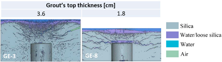
FIGURE 12. Vertical cross-section passing through the centre of the 3D reconstructed volume obtained via X-ray tomography, at the end of GE-3 and GE-8. Please refer to the supplementary material to access the 3D visualisation of the reconstructed volumes.
GE-8 exhibited extensive cracking upon temperature exposure. Within 10 min after temperature exposure, the top surface was observed to heave and crack, with a subsequent release of water vapour. Lateral cracking was also observed within the next hour. Upon microstructural X-ray analysis (Figure 12, right), it was shown that surface heaving was caused by the formation of a large void (up to 0.6 cm thick) directly above the heater. The reduced gel thickness above the heater (and, hence, reduced overburden) promoted cracking and lifting of the gel. This did not occur in GE-3. Wide horizontal cracks were also found to originate from the top of the heater, and to propagate outwards. Upon extrusion, the GE-8 gelled specimen failed in two pieces (an upper and lower layer) along the main horizontal temperature-induced crack, thus confirming a poorer performance when compared to all of the other grouting experiments.
Experiments GE-9, GE-10, and GE-11 have been conducted by grouting a porous media (glass beads, surrounding the heating element) to simulate the effect of grouting hot radioactive waste in rubble/particulate form. These experiments were carried out either by gelling the grout prior to heat exposure at silica concentration wt% 34 (GE-9), or by gelling the grout underwater during heat exposure at silica concentration wt% 34 and 17 (GE-10 and GE-11 respectively).
The results of the X-ray tomographies of GE-9, GE-10, and GE-11 are reported in Figure 13. Irrespective of the grouting condition and silica concentration, all gels performed well upon temperature exposure. None of the experiments showed the formation of major cracks. Some lower-density areas, above the heater, were identified as the preferential locations for water vapour transport, however no observable cracks propagated through the gel. The lack of cracks may be associated with the increased thermal diffusivity of the grouted glass bead samples (compared to the gel-only samples), promoting heat transfer due to the higher thermal diffusivity of glass (typically in the range of 0.3–0.4 mm2/s at 25°C, compared to <0.03 mm2/s for CS gel). In addition, the grouted glass bead samples exhibit enhanced strength properties, as shown in Section 3.1. Upon extrusion, all grouted samples remained intact. GE-11 was slightly more deformable than GE-9 and GE-10 because of the lower silica concentration, but could still be handled without any breakage.
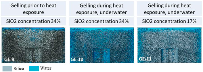
FIGURE 13. Vertical cross-section passing through the centre of the 3D reconstructed volume obtained via X-ray tomography, at the end of GE-9 to GE-11.
CS gels are made of a solid network of silica nanoparticles, and an aqueous solution filling up the porosity. Let us consider an area close to the heating element, as schematically shown in Figure 14. The increase in temperature reduces the solubility of any air dissolved in the gel’s pore water, thus leading to the formation of air-filled pockets (i.e. the pores are partially filled with air in a gaseous phase). If the temperature around the heater stays below the boiling point of the pore water, the local expansion of the air pockets does not cause diffused cracking throughout the gel, as observed in GE-1 at a temperature of 60°C.
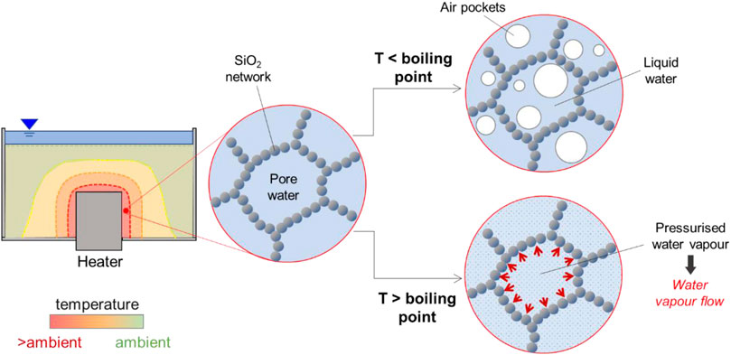
FIGURE 14. Temperature effects on the pore water contained within the silica hydrogel.
If the temperature exceeds the boiling point, the pore water itself also undergoes a change of phase from liquid to gas (water vapour), with an associated change in volume. This generates an excess pressure, triggering a flow of water vapour via two potential modes of transport: i) through the connected porosity of the silica hydrogel, and ii) via newly-formed connected cracks, induced by the tensile forces exerted by the pressurised water vapour on the surrounding silica network.
The preferential mode of water vapour transport is controlled by the combined effect of the gas permeability of the hydrogel and its stress-strain behaviour (Figure 15). If the gas permeability is high enough to accommodate the flow of water vapour through the gel’s connected porosity, temperature-induced tensile cracking is unlikely to occur. This is the case for the low-concentration silica gels; in this study, gels prepared at wt% 17 (GE-5, 6, 7 and 11), or gels potentially diluted by convective currents when grouting is carried out underwater (GE-4, 7). In these, the larger pore size of the silica network (as discussed in Section 3.2) promotes the transfer of water vapour through the pores. The high gas permeability, combined with the ductile nature of the gel (as discussed in Section 3.1), allows a gradual release of water vapour without significant pressure build-up, thus mitigating cracking (Figure 15A).
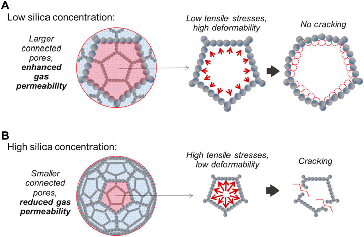
FIGURE 15. Temperature-induced cracking behaviour of hydrogels at (A) low silica concentration, and (B) high silica concentration. N.B. the regular 3D lattices in the figure are a purely qualitative representation of the gel’s porosity; real silica hydrogels are characterised by irregular (amorphous) structures.
On the other hand, gels characterised by lower gas permeability are more prone to temperature-induced tensile cracking (Figure 15B). This is the case for the high-concentration silica gels prepared at wt% 34, whose smaller pore size (as discussed in Section 3.2) hinders the flow of water vapour. The resulting development of high tensile stresses, together with the brittle nature of these gels (Section 3.1) leads to extensive cracking, as observed in GE-2, 3 and 8.
Besides temperature-induced cracking, the ability to maintain grout integrity upon retrieval and transport is crucial to the overall performance of the gel. This is controlled by the mechanical properties of the gel upon shearing. Gels with high shear strength and low deformability are less prone to damage upon handling, as opposed to low-strength, highly deformable gels. As shown in Section 3.1, the three main factors controlling the shear strength of silica hydrogels are the curing temperature, the curing time, and the silica concentration. An increase in any of these variables increases the shear strength of the gel, thus preventing/limiting breakage and material loss upon removal and transport. It is worth noting that, even in the adverse occurrence of gel failure along the temperature-induced cracks upon extrusion (e.g. as observed in GE-8), the loss of material is still limited—i.e., there is no release of airborne particulates.
Based on the mechanisms described above and on the results of the experimental campaign carried out in this study, the following guidance is given to optimise the performance of CS grouting around hot radioactive material prior to removal and transport, depending on the type of application.
1. If the temperature of the waste is below the boiling temperature of the gel’s pore water (i.e. water vapour is not formed), temperature-induced cracking is prevented. In this case, the use of a high-concentration silica grout is recommended, in order to improve the mechanical properties of the gel and reduce the risk of damage upon handling.
2. If the temperature of the waste is above the boiling point of the pore water, and grouting has to be carried out in dry conditions (e.g. when the coolant is lost or not present), lowering the silica concentration of the grout mix is preferable, in order to limit damage induced by tensile cracking. At the same time, care should be taken to keep the silica concentration high enough to ensure good handling of the gel upon removal and transport. Delaying the removal and transport operations for some time after grouting has taken place may also be advantageous, in order to allow the gel to gain enough strength to be handled safely.
3. If the temperature of the waste is above the boiling point, but grouting can still be carried out underwater, a high-concentration silica grout mix is recommended to ensure good handling upon removal and transport. This is because convection currents around the hot waste will naturally dilute the grout by mixing with the surrounding water, thus limiting tensile cracking.
4. For all applications, it is recommended to create a thick layer of grout above the heated object, this will avoid heaving and cracking which could undermine the integrity of the hydrogel upon removal.
The experimental campaign carried out in this study confirms the potential of colloidal silica (CS) grouting as a pre-treatment for nuclear waste and spent fuel prior to removal and transport operations, inhibiting the loss of air-borne and water-borne radioactive particulates.
Good performances upon temperature exposure and extrusion/handling were observed when an object at 60°C was encapsulated within the silica hydrogel, showing no temperature-induced cracking nor loss of integrity after 7 h of exposure. This confirms the suitability of the treatment in standard storage conditions.
At 120°C (simulating extreme scenarios where cooling is lost), the phase change of the hydrogel’s pore-water triggered the formation of tensile cracks in some samples. Temperature-induced cracking was attenuated for low silica concentration hydrogels, either when the as-delivered CS was diluted upon grout mixing, or as an effect of carrying out grouting operations underwater. However, a low concentration of silica nanoparticles made the hydrogel more prone to loss of integrity upon removal and transport, which is crucial to the overall performance of the treatment. These results suggest that the silica concentration of the grout mix should be carefully designed depending on the type of application (e.g. temperature of the radioactive material at the time of removal/transport, presence/absence of cooling water), in order to minimise temperature-induced cracking whilst ensuring that the integrity of the grouted waste can be maintained during removal and transport operations.
The results presented in this work have strong relevance to the decommissioning of nuclear plants worldwide, including damaged structures (e.g., Chernobyl and Fukushima reactors). Further research is needed to assess the radiation stability of CS hydrogels, to identify suitable durations of radiation exposure at which the integrity of the hydrogel is not compromised.
The original contributions presented in the study are included in the article/Supplementary Material. All data underpinning this publication are openly available from the University of Strathclyde KnowledgeBase at https://doi.org/10.15129/67c6f416-a8e6-43c5-8381-edfc645003f6.
AP (first author, corresponding author): Conducting research and investigation process, specifically performing the experiments, and data/evidence collection; Provision of study materials; Writing-up and visualisation. GE: Conceptualisation (formulation overarching research goals and aims) and supervision. RL: Conceptualisation (formulation overarching research goals and aims) and supervision; Project administration; Funding acquisition.
This research was funded by the Engineering and Physical Sciences Research Council (EPSRC) [EP/S01019X/1].
The authors gratefully acknowledge Master Builders Solutions for providing the colloidal silica suspension used in this study. The authors also wish to thank Derek McNee for manufacturing the stainless steel cylinder in the grouting experimental setup.
The authors declare that the research was conducted in the absence of any commercial or financial relationships that could be construed as a potential conflict of interest.
All claims expressed in this article are solely those of the authors and do not necessarily represent those of their affiliated organizations, or those of the publisher, the editors and the reviewers. Any product that may be evaluated in this article, or claim that may be made by its manufacturer, is not guaranteed or endorsed by the publisher.
For the purpose of Open Access, the authors have applied a Creative Commons Attribution (CC BY) to any Author Accepted Manuscript (AAM) version arising from this submission.
The Supplementary Material for this article can be found online at: https://www.frontiersin.org/articles/10.3389/fenrg.2023.1156301/full#supplementary-material
Bahadur, A. K., Holter, K. G., and Pengelly, A. (2007). “Cost-effective pre-injection with rapid hardening microcement and colloidal silica for water ingress reduction and stabilisation of adverse conditions in a headrace tunnel,” in Underground space – the 4th dimension of metropolises. Editors Z. Barták (London: Taylor & Francis Group), 297–301.
Bergna, H. E., and Roberts, W. O. (2005). Colloidal silica fundamentals and applications. Boca Raton: CRC Press. doi:10.1201/9781420028706
Bots, P., Renshaw, J. C., Payne, T. E., Comarmond, M. J., Schellenger, A. E. P., Pedrotti, M., et al. (2020). Geochemical evidence for the application of nanoparticulate colloidal silica gel for in situ containment of legacy nuclear wastes. Environ. Sci. Nano 7 (5), 1481–1495. doi:10.1039/d0en00046a
Butrón, C., Gustafson, G., Fransson, Å., and Funehag, J. (2010). Drip sealing of tunnels in hard rock: A new concept for the design and evaluation of permeation grouting. Tunn. Undergr. Space Technol. 25, 114–121. doi:10.1016/j.tust.2009.09.008
Gallagher, P. M., and Mitchell, J. K. (2002). Influence of colloidal silica grout on liquefaction potential and cyclic undrained behavior of loose sand. Soil Dyn. Earthq. Eng. 22, 1017–1026. doi:10.1016/s0267-7261(02)00126-4
Gin, S., Jollivet, P., Tribet, M., Peuget, S., and Schuller, S. (2017). Radionuclides containment in nuclear glasses: An overview. Radiochim. Acta 105 (11), 927–959. doi:10.1515/ract-2016-2658
Hunt, J. D., Ezzedine, S. M., Bourcier, W., and Roberts, S. (2013). “Kinetics of the gelation of colloidal silica at geothermal conditions, and implications for reservoir modification and management,” in Proceedings Thirty-Eighth Workshop on Geothermal Reservoir Engineering Stanford University, Stanford, California, February 11-13, 2013. SGP-TR-198.
Karyakin, Y. E., Peich, N. N., Pletnev, A. A., and Fedorovich, E. D. (2019). Methods of emergency heat removal from pools and storages of spent fuel of nuclear power plants. J. Eng. Phys. Thermophys. 92, 553–561. doi:10.1007/s10891-019-01963-1
NEA & OECD (2020). Storage of radioactive waste and spent fuel, s.l.: Radioactive waste management and decommissioning 2020.
Pagano, A. G., El Mountassir, G., and Lunn, R. J. (2021). Performance of colloidal silica grout at elevated temperatures and pressures for cement fracture sealing at depth. J. Petroleum Sci. Eng. 208, 109782. doi:10.1016/j.petrol.2021.109782
Persoff, P., Apps, J., Moridis, G., and Whang, J. M. (1999). Effect of dilution and contaminants on sand grouted with colloidal silica. Jouranl Geotechnical Geoenvironmental Eng. 125 (6), 461–469. doi:10.1061/(asce)1090-0241(1999)125:6(461)
van Genuchten, M. T. (1980). A closed-form equation for predicting the hydraulic conductivity of unsaturated soils. Soil Sci. Soc. Am. J. 44, 892–898. doi:10.2136/sssaj1980.03615995004400050002x
Varlakov, A., and Zherebtsov, A. (2021). “Innovative and conventional materials and designs of nuclear cementitious systems in radioactive waste management,” in Sustainability of life cycle management for nuclear cementation-based technologies. doi:10.1016/B978-0-12-818328-1.00004-6
Vitkova, M., Gorinov, I., and Dacheva, D. (2006). “Safety criteria for wet and dry spent fuel storage,” in International conference on WWER fuel performance, modelling and experimental support, 19-23 Sep 2005, Albena (Bulgaria).
Keywords: colloidal silica grouting, encapsulation of radioactive waste, temperature effect, hazard mitigation, removal and transport of radioactive waste
Citation: Pagano AG, El Mountassir G and Lunn RJ (2023) Colloidal silica as a grouting material for the temporary encapsulation of heat-generating radioactive waste during removal and transport operations: A proof of concept. Front. Energy Res. 11:1156301. doi: 10.3389/fenrg.2023.1156301
Received: 01 February 2023; Accepted: 22 March 2023;
Published: 04 April 2023.
Edited by:
Hosam Saleh, Egyptian Atomic Energy Authority, EgyptReviewed by:
Michael Ojovan, Imperial College London, United KingdomCopyright © 2023 Pagano, El Mountassir and Lunn. This is an open-access article distributed under the terms of the Creative Commons Attribution License (CC BY). The use, distribution or reproduction in other forums is permitted, provided the original author(s) and the copyright owner(s) are credited and that the original publication in this journal is cited, in accordance with accepted academic practice. No use, distribution or reproduction is permitted which does not comply with these terms.
*Correspondence: Arianna Gea Pagano, YXJpYW5uYS5wYWdhbm9AZ2xhc2dvdy5hYy51aw==
†Present address: Arianna Gea Pagano, Division of Infrastructure and Environment, University of Glasgow, Glasgow, United Kingdom
Disclaimer: All claims expressed in this article are solely those of the authors and do not necessarily represent those of their affiliated organizations, or those of the publisher, the editors and the reviewers. Any product that may be evaluated in this article or claim that may be made by its manufacturer is not guaranteed or endorsed by the publisher.
Research integrity at Frontiers
Learn more about the work of our research integrity team to safeguard the quality of each article we publish.