 Guo-Jian Ji
 Jin-Ming Gu
 Zhi Chen1
94% of researchers rate our articles as excellent or good
Learn more about the work of our research integrity team to safeguard the quality of each article we publish.
Find out more
ORIGINAL RESEARCH article
Front. Energy Res., 15 May 2023
Sec. Solar Energy
Volume 11 - 2023 | https://doi.org/10.3389/fenrg.2023.1150326
HITEC molten salt (7% NaNO3, 53% KNO3, 40% NaNO2) has been identified as a suitable heat transfer fluid for concentrated solar power (CSP) systems, such as parabolic trough collectors (PTC) and evacuated tube solar collectors (ETSC). In order to optimize the flow and heat transfer performance of HITEC in ETSC, a molten salt heat transfer test rig was built to conduct an experimental study, varying inlet and outlet temperatures and mass flow rates of HITEC. Results show that the heat loss of HITEC in ETSC is lower than the other tubes. The convective heat transfer coefficient of HITEC is much lower than that of HITEC in round tube. Because the experimental data of HITEC in ETSC largely differed from the classical correlation equations, a new empirical heat transfer correlation equation was set for HITEC in ETSC, and the deviation between the experiment data and new correlation was within ±19.2%. Finally, by comparing the inlet and outlet temperatures of ETSC under different irradiation intensities, it is concluded that the ETSC can work stably when the temperature exceeds 700 W/m2.
· The flow and heat transfer characteristics of HITEC in ETSC were investigated based on the molten salt circulation heat transfer test rig.
· The forced convective correlation between Nu and Re of HITEC in the ETSC was fitted.
· The radiative heat transfer of ETSC was experimented and effective radiation was studied under steady solar irradiation intensity.
The parabolic trough collector (PTC) is a promising technology for large-scale commercialization of concentrated solar power (CSP) systems due to its cost-effectiveness (Bamisile et al., 2022; Felsberger et al., 2022). Similar to conventional power plants, power is generated and driven by thermal energy converted from solar radiation through Rankine cycle in PTC system (Begdouri and El Fadar, 2022; Goyal and Reddy, 2022; Shajan and Baiju, 2022). Heat collector elements (HCE) are located in the focal line of the parabolic mirrors, where they absorb and transform the concentrated sunlight into thermal energy (Saedodin et al., 2021; Nabi et al., 2022). Steam is generated from the heat transfer fluid (HTF) flowing inside HCE through the heat exchanger (Nakar and Feuermann, 2016; Selikhov et al., 2022; Vengadesan et al., 2022). Therefore, the HTF’s enhanced heat transfer features are essential to maximizing PTC system’s efficiency. Solutions include using HTF with higher operating temperatures, good thermal stability, high volumetric heat capacity, and high thermal conductivity to reduce pump consumption (Ashoori and Gates, 2022; Gao et al., 2022; Li et al., 2022). Thermal oil has already been applied in PTC systems, which is stable at operating temperatures below 400°C and tends to decompose at higher temperatures. Further efforts have also been made to develop direct steam generation (DSG) technology, which can reduce thermal loss without the need for an extra heat exchanger since water gets vaporized in absorber tubes directly and higher temperatures can be achieved (Pal and Kumar, 2021; Li et al., 2022). Another approach is using molten salt as the HTF, which has already served as thermal energy storage medium in CSP plants for continuous power generation (Iodice et al., 2020).
To optimize the efficiency of CSP systems, it is important to investigate the heat transfer characteristics of molten salt and evaluate its capabilities as a HTF in PTC. Extensive research has been conducted on the convective heat transfer coefficient of different molten salt in circular tubes, such as FLiNaK (LiF, NaF, KF) and HITEC (7% NaNO3, 53% KNO3, 40% NaNO2) (Hoffman and Lones, 1955; Hoffman and Cohen, 1960; Liu et al., 2010). The influence of structural parameters, includes helical pitch and wire with coiled wire plug-ins, on heat transfer in annular flow channels has been investigated, taking into consideration the HTF and other factors (Yang et al., 2021). Correlation formulas have been proposed to reveal the convective heat transfer performance of molten salt in annular channels with coils (Lu et al., 2014; Kim et al., 2018). Besides, the convective heat transfer characteristic of molten salt-based nanofluid was numerically studied to investigate the influence of inlet velocities and heat flux (Ying et al., 2020). Heat transfer of salt outside the coiled tube was reported and correlations were proposed (Huang et al., 2021). The heat transfer mechanism of the U-tube molten salt steam generator was experimentally revealed, and thermal efficiency was determined by heat absorption and heat loss (Zou et al., 2020). An experimental investigation on the heat transfer performance of molten salt flowing in an annular tube was carried out with different inlet temperatures (Dong et al., 2019). Experimental study of heat transfer enhancement for molten salt with transversely grooved tube heat exchanger in laminar-transition-turbulent regimes was investigated with the increasing of Re and Pr (Chen et al., 2018).
Related researches on the heat transfer characteristics of molten salt are shown in Table 1.
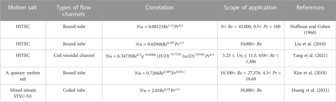
TABLE 1. Related researches on the heat transfer characteristics of molten salt.
Currently, there has been little researches on the flow heat transfer of molten salts in ETSC, which is of great significance for designing the heat-absorbing heat transfer component of the HITEC in ETSC and calculating of heat transfer characteristics of ETSC. Therefore, the flow and heat transfer characteristics of HITEC in ETSC were experimented with the different mass flow and operating temperatures. The Nusselt number of fully developed turbulent flow was analyzed to provide the forced convection heat transfer characteristic of HITEC in ETSC. The accuracy of these correlations on the HITEC data of this study was examined with comparisons between the experiment results of HITEC in ETSC and classical heat transfer empirical correlations as basis. Finally, in order to promote the industrial application of HITEC in ETSC, and explore whether the PTC systems can work stably under low irradiation intensity, the thermal performance of ETSC was studied with the different solar irradiances.
The molten salt heat transfer test rig mainly consists of the molten salt tank with pump, ETSC, sunlight simulator and parabolic mirror, as shown in Figure 1. Flex hoses are arranged on the corner of the stainless-steel pipelines in consideration of the thermal expansion at operating temperatures.
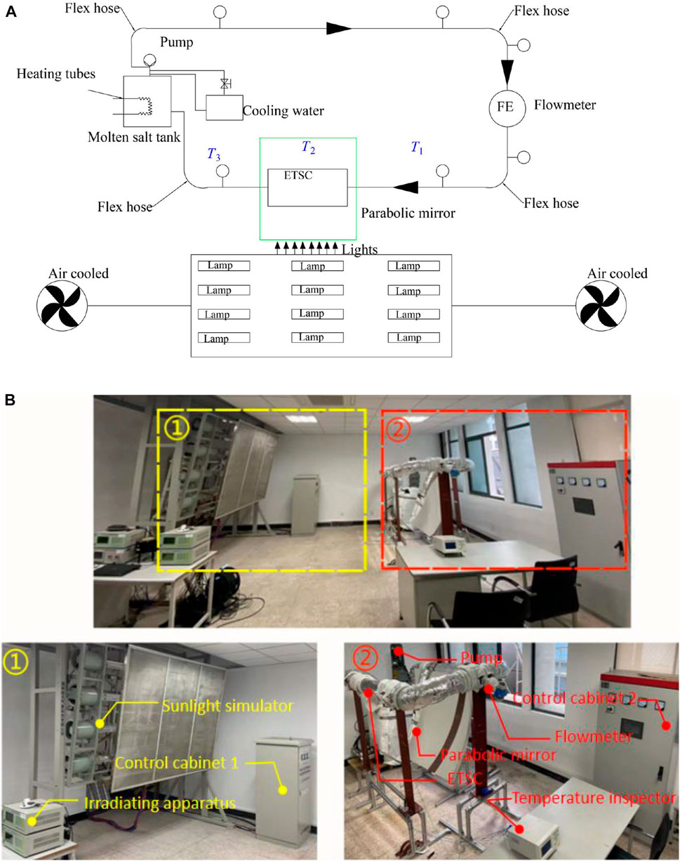
FIGURE 1. (A) Schematic diagram of molten salt heat transfer test rig. (B) Photos of the test rig.
Three 3-kW electric heating tubes were installed inside the 0.3 m3 molten salt tank. And at least 0.15 m3 molten salt was injected for the experiment to ensure the safety of the molten-salt pump. The solar simulator, which has a steady and adjustable solar irradiation intensity from 0 W/m2 to 1000 W/m2, consists of 12 lamps that can concentrate solar light on the surface of the ETSC. The length and width of the mirror are 1,356 mm and 1,463 mm, respectively, and the mirror’s focal length is 850 mm.
The structure of the ETSC is depicted in Figure 2, which consists of an inner absorber tube and an outer glass envelope. The solar selective coating on the outer surface of the absorber tube not only maximizes solar absorption in the spectral range of 0.25–2.5
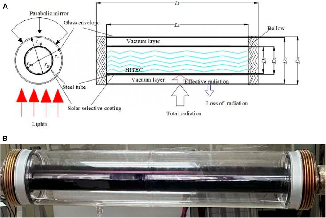
FIGURE 2. (A) Structure of the ETSC with heat transfer process illustrated (B) Photograph of the ETSC for experiment.
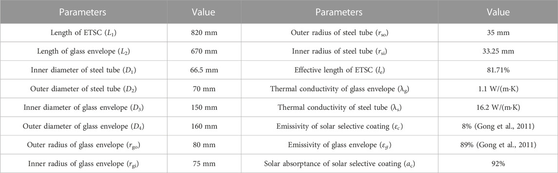
TABLE 2. The structural parameters and properties of the ETSC for experiment.
It can be seen from Figure 1A that two thermocouples, T1 and T2, were added and arranged at the inlet and outlet of the ETSC. A thermocouple was arranged to measure the temperature of the environment, Tair.
The structure and thermal properties of the ETSC and HITEC are summarized in Tables 2, 3 and, respectively.
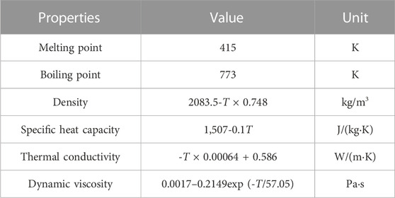
TABLE 3. Thermal properties of the HITEC molten salt (Wu et al., 2012).
The mass flow of HITEC was adjusted by varying the frequency of the drive motor of the molten salt pump. The target plate of the high-temperature resistant target flowmeter was also changed to achieve mass flow rates ranging from 0 to 1.4 kg/s and 0–3.78 kg/s.
The experimental process is shown in Figure 3.
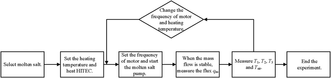
FIGURE 3. Flow diagram of experimental process.
In the circulation, the molten salt is driven by the molten salt pump and flows from the molten salt tank through the flowmeter and ETSC before returning to the tank.
During the experiment, the Re of HITEC molten salt in ETSC was gradually increased by increasing the flow rate while maintaining the temperature above 423 K, which ensured that HITEC was in a fully developed turbulent state. When the temperature of the molten salt was 423 K and the flow velocity was 0.15 m/s, the Re was 2,291.58, which is close to the critical Re of 2,300.
In the experiment, the inlet and outlet temperature of HITEC molten salt in ETSC, the surface temperature of ETSC, the temperature of atmospheric air and the flow rate of HITEC molten salt were measured to calculate the heat loss of ETSC and the convective heat transfer coefficient of molten salt in ETSC. The flow rate of HITEC salt was set differently in various experiments (flow rates ranged from 1.25 kg/s to 3.07 kg/s continuously in 11 experiments). In each flow rate, three inlet temperatures of HITEC were used (about 463 K, 493 K, and 523 K). The uncertainties of the experiment measurements are listed in Table 4.
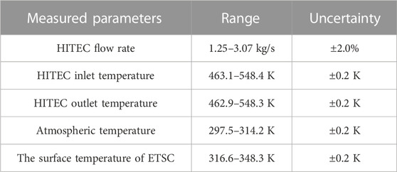
TABLE 4. Range of measured parameters.
Investigation of the heat loss of molten salt in the ETSC is based on the analysis of the heat transfer process as shown in Figure 4, when the solar simulator is off and the solar radiation is zero.

FIGURE 4. Diagram of heat transfer process.
The heat transfer equation of the ETSC can be described according to energy conservation law as Eq. 1:
where qall is the total solar radiation per unit time of the ETSC, W. qout is the heat loss per unit time of the ETSC, W. qe is the effective thermal energy per unit time collected by the ESTC.
where hair is the convective heat transfer coefficient of atmospheric air which is equal to
Considering that there was no wind in the room, the heat loss of glass envelope to the atmospheric air can be carried out in the form of natural convection. Nu can be calculated by Eq. 3; (Gong et al., 2011):
where Ra is Rayleigh number, and it can be calculated by Eq. 4 (Gong et al., 2011):
where g is 9.18 m/s2, βair is 3.4 × 10⁻³ K−1 and is the thermal expansion coefficient of atmospheric air, ΔT is the temperature difference between atmospheric air and the glass envelope, αair is the thermal diffusivity of atmospheric air.
The heat loss of the ETSC has been calculated by the Eq. 2 and is also equal to the heat transfer between the HITEC and the steel tube according to Eq. 5.
where As is the area of the inner wall of steel tube. Tms is equal to (T1+T2)/2, which is measured by the experiment. To obtain the convective heat transfer coefficient hms, the inner wall temperature of steel tube Tsi need be calculated.
The convective heat transfer between residual gas and the outer surface of absorber tube can be ignored because of the annular vacuum below 10−3 Pa (Bei, 2010). And the radiation heat transfer between the glass envelope and the environment also can be ignored (Bei, 2010).
The heat transfer can be described according to the law of energy conservation as Eq. 6:
The inner wall temperature of the glass envelope Tgi and the outer wall temperature of the steel tube Tso can be obtained according to the Eqs. 7, 8 respectively according the law of energy conservation. And then the inner wall temperature of steel tube Tsi can be carried out by Eq. 9.
For fully developed turbulent flow of HITEC in ETSC, the HITEC’s operating temperature and flow velocity increased from 473 K to 573 K and 1 kg/s to 3.2 kg/s, respectively, and the Re is larger than 10,000 in this experiment. In this case, Pr ranges from 8.36 to 8.64 which is based on the definition of Pr and Re as follows.
Where D1 is the diameter of the steel tube of the ETSC, ρ is the density of the HITEC, v and μ are the HITEC’s fluid flow velocity and dynamic viscosity, respectively. ʋ and α are the HITEC’s kinematic viscosity and thermal diffusivity, respectively.
In order to find out the influence of heat transfer characteristics, Nu can be calculated with the given Eq. 12.
Nu can be represented by Re and Pr as Eq. 13:
Where b, c and d are all constants, and since the ETSC in this experiment was cooling, d can be set as 0.3 (Dittus and Boelter, 1985), while the other two parameters can be fitted with the experimental data in the way of Levenberg-Marquardt.
In terms of the various inlet temperatures of HITEC in this study, the Re of HITEC in ETSC varies from 13,204 to 29,258. In addition, the heat transfer coefficient of HITEC in ETSC varies from 299.8 W/(m2·K) to 833.05 W/(m2·K). Figure 5 shows that the heat transfer coefficient (hms) increase gradually with the increase in Re. hms in this study is much lower than the heat transfer coefficient h of others (Hoffman and Cohen, 1960; Liu et al., 2010). This outcome is mainly because of lower heat exchange between ETSC and atmospheric air compared with round tube under the same operating condition.
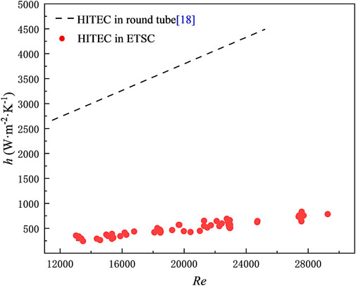
FIGURE 5. Variation of convective heat transfer coefficient h of HITEC in ETSC with Re.
The experimental data of HITEC are compared with the traditional classical correlation. The results are shown in Figure 6. The maximum deviations of the experimental data from the Dittus-Boelter formula (Dittus and Boelter, 1985) and H.W. Hoffman formula (Hoffman and Cohen, 1960) are 19.8% and 57.3%, respectively. The reasons why the large deviation between the data and the traditional classical correlation exist are as follows.
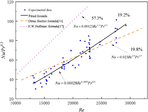
FIGURE 6. Fitted correlation between Nu/Pr0.3 and Re compared with experimental data.
The vacuum layer of ETSC leads to the low heat exchange with the atmospheric air, which also means that the heat transfer between HITEC and ETSC is low in the cooling state.
The structure parameters of ETSC are different from those of round tube. The diameter of ETSC is much larger than that of round tube, which leads to a larger molten salt flow area.
Compared with the influence of the temperature difference between inlet and outlet of ETSC, the influence of changes in flow area and heat loss is stronger. That is why the deviation between the data and the traditional classical correlation is large.
From the experimental data of HITEC in ETSC, the fitted calculation for HITEC convective heat transfer in ETSC is obtained in range of 8.36< Pr < 8.64, 13,204< Re < 29,258, and it can be described as:
The new correlation can predict the experimental data with an accuracy of ±19.2%, which establishes a good convective heat transfer correlation.
The formula fitted by Wu (Liu et al., 2010) is compared with the experimental data in Figure 7.
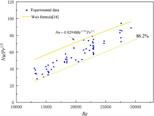
FIGURE 7. Experimental data compared with formula of Wu.
The maximum deviation of experimental data is 86.2%. It means that the formula describing heat transfer of HITEC in a round tube is not suitable for HITEC in ETSC.
It is evident that the hms calculated by the Eq. 5 ranges from 299.8 W/(m2·K) to 833.05 W/(m2·K), while that of Wu is more than 2,500 W/(m2·K), and the heat loss of the ETSC is lower. So that Nu is lower than that of round tube. Pr is affected by thermal properties and is almost unchangeable at the same temperature. That is why Nu/Pr0.3 of the ETSC is larger than that of round tube. And it also means that the traditional classical formulas are no longer suitable for HITEC in ETSC.
The operation of CSP plants directly related to the temperature difference between the inlet and outlet of ETSC. Therefore, we studied the temperature difference under different irradiation intensities. The temperature difference is shown in Figure 8 under the steady irradiation intensity of 0 W/m2, 400 W/m2, 500 W/m2, 600 W/m2 and 700 W/m2 ΔT increases from −0.30∼ −0.2 K to −0.2–0 K, and the effective thermal energy per unit time increases from −26.8 W to 190.28 W, which can be computed by Eq. 2.
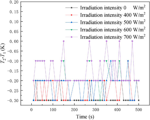
FIGURE 8. Temperature difference with the change of irradiation intensity.
There are two reasons why ΔT is still equal to or lesser than 0 K. First, the experimental effective length of ETSC le is 81.71%, which is smaller than the 96.25% used in CSP. Second, the increase in the temperature difference 0.2°C of molten salt at the inlet and outlet of the ETSC is determined by the irradiation intensity of the concentrating part of the ETSC. This work uses a single parabolic mirror with the concentrating ratio about 17. When the irradiation intensity rises from 0 W/m2 to 700 W/m2, the irradiation intensity of the concentrating part rises from 0 W/m2 to 11,900 W/m2. In CSP plants, the concentrating ratio of the collector is in the range of 50–68 (Bei, 2010). When the irradiation intensity is 700 W/m2, the lowest irradiation intensity of the concentrated part is 35,000 W/m2. The irradiation intensity of the concentrated part is 23,100 W/m2 more than that of experiment. According to this calculation, the temperature difference between the inlet and outlet of molten salt can be increased by 0.39°C. Therefore, when the irradiation intensity reaches 700 W/m2, the outlet temperature of the ETSC is much higher than the inlet temperature, and the CSP plant can work normally.
The convection heat transfer experiment of HITEC in ETSC are conducted and compared in this work. The results are as follows:
(1) Due to the low heat exchange between ETSC and HITEC, the heat transfer coefficient of HITEC in ETSC ranges from 299.8 W/(m2·K) to 833.05 W/(m2·K), which is lower than that of HITEC in a round tube.
(2) The experimental data of HITEC shows a large difference from classical heat transfer correlations, indicating that the classical heat transfer correlations are no longer suitable for the flow and heat transfer of HITEC in ETSC.
(3) The experimental data on forced convective heat transfer in ETSC of fully developed turbulent flow was obtained. The Re of the HITEC ranged from 13,204 to 29,258, the Pr fell between 8.36 and 8.64. The corresponding convective heat transfer correlation equation for HITEC was fitted as
(4) The temperature difference between the inlet and outlet of the ETSC was compared with the different steady solar irradiation intensities from 0 W/m2 to 700 W/m2, and ΔT increases from −0.30∼ −0.2 K to −0.2–0 K. The thermal flux of the ETSC increases from −40 W/m to 284 W/m. The experimental results show that the ETSC can work stably when the irradiation intensity reaches 700 W/m2. This conclusion can provide some theoretical basis for determining the location of CSP plant.
The original contributions presented in the study are included in the article/Supplementary Materials, further inquiries can be directed to the corresponding author.
For research articles with several authors, a short paragraph specifying their individual contributions must be provided. The following statements should be used “conceptualization, G-JJ and J-MG; methodology, G-JJ; software, ZC; validation, J-MG and ZC; formal analysis, J-MG; investigation, G-JJ; resources, B-BL; data curation, YG; writing—original draft preparation, J-MG; writing—review and editing, G-JJ and J-MGu; visualization, J-MG; supervision, ZC; project administration, G-JJ; funding acquisition, G-JJ. All authors have read and agreed to the published version of the manuscript.
This work was supported by Postgraduate Research and Practice Innovation Program of Jiangsu Province (Grant No. KYCX22_3043) and Changzhou University Fund (Grant No. ZMF21020034).
The authors declare that the research was conducted in the absence of any commercial or financial relationships that could be construed as a potential conflict of interest.
All claims expressed in this article are solely those of the authors and do not necessarily represent those of their affiliated organizations, or those of the publisher, the editors and the reviewers. Any product that may be evaluated in this article, or claim that may be made by its manufacturer, is not guaranteed or endorsed by the publisher.
The Supplementary Material for this article can be found online at: https://www.frontiersin.org/articles/10.3389/fenrg.2023.1150326/full#supplementary-material
Ashoori, S., and Gates, I. D. (2022). Carbon intensity of in-situ oil sands operations with direct contact steam generation lower than that of once-through steam generation. J. Clean. Prod. 367, 133046. doi:10.1016/j.jclepro.2022.133046
Bamisile, O., Cai, D., Adun, H., Adedeji, M., Dagbasi, M., Dika, F., et al. (2022). A brief review and comparative evaluation of nanofluid application in solar parabolic trough and flat plate collectors. Energy Rep. 8, 156–166. doi:10.1016/j.egyr.2022.08.078
Begdouri, O. A., and El Fadar, A. (2022). Impact of parabolic trough collector model on the CSP plants’ performance. Therm. Sci. Eng. Prog. 34, 101434. doi:10.1016/j.tsep.2022.101434
Bei, Z.-H. (2010). Study on heat loss mechanism of parabolic trough solar collector. Hebei: North China Electric Power University.
Chen, Y., Tian, J., Fu, Y., Tang, Z., Zhu, H., and Wang, N. (2018). Experimental study of heat transfer enhancement for molten salt with transversely grooved tube heat exchanger in laminar-transition-turbulent regimes. Appl. Therm. Eng. 132, 95–101. doi:10.1016/j.applthermaleng.2017.12.054
Dittus, F., and Boelter, L. (1985). Heat transfer in automobile radiators of the tubular type. Int. Commun. heat mass Transf. 12 (1), 3–22. doi:10.1016/0735-1933(85)90003-x
Dong, X., Bi, Q., and Yao, F. (2019). Experimental investigation on the heat transfer performance of molten salt flowing in an annular tube. Exp. Therm. Fluid Sci. 102, 113–122. doi:10.1016/j.expthermflusci.2018.11.003
Felsberger, R., Buchroithner, A., Gerl, B., Schweighofer, B., Preßmair, R., Mitter, T., et al. (2022). Optical performance and alignment characterization of a parabolic trough collector using a multi-junction CPV solar cell. Sol. Energy 239, 40–49. doi:10.1016/j.solener.2022.04.058
Gao, D., Li, J., Ren, X., Hu, T., and Pei, G. (2022). A novel direct steam generation system based on the high-vacuum insulated flat plate solar collector. Renew. Energy 197, 966–977. doi:10.1016/j.renene.2022.07.102
Gong, G.-J., Wang, J., Huang, X., Hao, M.-L., and Zhang, Y. (2011). Study on heat loss of trough solar vacuum collector tube. J. Sol. Energy 32 (04), 517–522.
Goyal, R., and Reddy, K. (2022). Numerical investigation of entropy generation in a solar parabolic trough collector using supercritical carbon dioxide as heat transfer fluid. Appl. Therm. Eng. 208, 118246. doi:10.1016/j.applthermaleng.2022.118246
Hoffman, H., and Cohen, S. (1960). Fused salt heat TRANSFER--PART III: FORCED-CONVECTION heat transfer in circular tubes containing the salt mixture NaNO $ sub 2$-NANO $ sub 3$-KNO $ sub 3$. Tenn: Oak Ridge National Lab.
Hoffman, H., and Lones, J. (1955). Fused Salt Heat Transfer. Part II. Forced convection heat transfer in circular tubes containing NaF-KF-LiF eutectic. Tenn: Oak Ridge National Lab.
Huang, Z., Zou, Y., Wei, X., Ding, J., and Lu, J. (2021). Mixed convection heat transfer of molten salt outside coiled tube. Int. Commun. Heat Mass Transf. 120, 105004. doi:10.1016/j.icheatmasstransfer.2020.105004
Iodice, P., Langella, G., and Amoresano, A. (2020). Direct steam generation solar systems with screw expanders and parabolic trough collectors: Energetic assessment at part-load operating conditions. Case Stud. Therm. Eng. 19, 100611. doi:10.1016/j.csite.2020.100611
Kim, H., Kim, H., Lee, S., and Kim, J. (2018). A study on heat transfer characteristics of quinary molten salt mixture. Int. J. Heat Mass Transf. 127, 465–472. doi:10.1016/j.ijheatmasstransfer.2018.08.029
Li, P., Lin, H., Li, J., Cao, Q., Wang, Y., Pei, G., et al. (2022). Analysis of a direct vapor generation system using cascade steam-organic Rankine cycle and two-tank oil storage. Energy 257, 124776. doi:10.1016/j.energy.2022.124776
Liu, B., Wu, Y.-T., Ma, C.-F., and Zhao, Y. (2010). Experimental study on forced convective heat transfer of molten salt in round tube. J. Eng. Thermophys. 31 (10), 1739–1742.
Lu, J., He, S., Ding, J., Yang, J., and Liang, J. (2014). Convective heat transfer of high temperature molten salt in a vertical annular duct with cooled wall. Appl. Therm. Eng. 73 (2), 1519–1524. doi:10.1016/j.applthermaleng.2014.05.098
Nabi, H., Pourfallah, M., Gholinia, M., and Jahanian, O. (2022). Increasing heat transfer in flat plate solar collectors using various forms of turbulence-inducing elements and CNTs-CuO hybrid nanofluids. Case Stud. Therm. Eng. 33, 101909. doi:10.1016/j.csite.2022.101909
Nakar, D., and Feuermann, D. (2016). Surface roughness impact on the heat loss of solar vacuum heat collector elements (HCE). Renew. Energy 96, 148–156. doi:10.1016/j.renene.2016.04.041
Pal, R. K., and Kumar, R. (2021). Two-fluid modeling of direct steam generation in the receiver of parabolic trough solar collector with non-uniform heat flux. Energy 226, 120308. doi:10.1016/j.energy.2021.120308
Plumpe, A. (2016). Design of a test rig and its testing methods for rotation and expansion performing assemblies in parabolic trough collector power plants. Aachen: RWTH Aachen.
Saedodin, S., Zaboli, M., and Ajarostaghi, S. S. M. (2021). Hydrothermal analysis of heat transfer and thermal performance characteristics in a parabolic trough solar collector with Turbulence-Inducing elements. Sustain. Energy Technol. Assessments 46, 101266. doi:10.1016/j.seta.2021.101266
Selikhov, Y., Klemeš, J. J., Kapustenko, P., and Arsenyeva, O. (2022). The study of flat plate solar collector with absorbing elements from a polymer material. Energy 256, 124677. doi:10.1016/j.energy.2022.124677
Shajan, S., and Baiju, V. (2022). Designing a novel small-scale parabolic trough solar thermal collector with secondary reflector for uniform heat flux distribution. Appl. Therm. Eng. 213, 118660. doi:10.1016/j.applthermaleng.2022.118660
Vengadesan, E., Bharathwaj, D., Kumar, B. S., and Senthil, R. (2022). Experimental study on heat storage integrated flat plate solar collector for combined water and air heating in buildings. Appl. Therm. Eng. 216, 119105. doi:10.1016/j.applthermaleng.2022.119105
Wu, Y.-T., Chen, C., Liu, B., and Ma, C.-F. (2012). Investigation on forced convective heat transfer of molten salts in circular tubes. Int. Commun. heat mass Transf. 39 (10), 1550–1555. doi:10.1016/j.icheatmasstransfer.2012.09.002
Yang, Y., Li, M., Zou, Y., and Chen, J. (2021). Numerical study on heat transfer characteristics of molten salt in annular channel with wire coil. Appl. Therm. Eng. 199, 117520. doi:10.1016/j.applthermaleng.2021.117520
Ying, Z., He, B., Su, L., Kuang, Y., He, D., and Lin, C. (2020). Convective heat transfer of molten salt-based nanofluid in a receiver tube with non-uniform heat flux. Appl. Therm. Eng. 181, 115922. doi:10.1016/j.applthermaleng.2020.115922
Zou, Y., Ding, J., Wang, W., Lee, D., and Lu, J. (2020). Heat transfer performance of U-tube molten salt steam generator. Int. J. Heat Mass Transf. 160, 120200. doi:10.1016/j.ijheatmasstransfer.2020.120200
Keywords: HITEC, Evacuated tube solar vacuum, convective heat transfer, molten salt, CSP, radiative heat transfer
Citation: Ji G-J, Gu J-M, Chen Z, Lu B-B and Gao Y (2023) Experimental research on heat transfer characteristic of HITEC molten salt in evacuated tube solar collector. Front. Energy Res. 11:1150326. doi: 10.3389/fenrg.2023.1150326
Received: 24 January 2023; Accepted: 04 May 2023;
Published: 15 May 2023.
Edited by:
Sendhil Kumar Natarajan, National Institute of Technology Puducherry, IndiaReviewed by:
Subbarama Kousik Suraparaju, Sri Vasavi Engineering College, IndiaCopyright © 2023 Ji, Gu, Chen, Lu and Gao. This is an open-access article distributed under the terms of the Creative Commons Attribution License (CC BY). The use, distribution or reproduction in other forums is permitted, provided the original author(s) and the copyright owner(s) are credited and that the original publication in this journal is cited, in accordance with accepted academic practice. No use, distribution or reproduction is permitted which does not comply with these terms.
*Correspondence: Bei-Bei Lu, bGJiQGNjenUuZWR1LmNu
Disclaimer: All claims expressed in this article are solely those of the authors and do not necessarily represent those of their affiliated organizations, or those of the publisher, the editors and the reviewers. Any product that may be evaluated in this article or claim that may be made by its manufacturer is not guaranteed or endorsed by the publisher.
Research integrity at Frontiers
Learn more about the work of our research integrity team to safeguard the quality of each article we publish.