 Yu Li1,2
 Dongdong Han
 Wenhua Wang
 Xin Li
95% of researchers rate our articles as excellent or good
Learn more about the work of our research integrity team to safeguard the quality of each article we publish.
Find out more
ORIGINAL RESEARCH article
Front. Energy Res. , 09 May 2023
Sec. Wind Energy
Volume 11 - 2023 | https://doi.org/10.3389/fenrg.2023.1140792
This article is part of the Research Topic Advances in Modeling and Simulation of Wind and Solar Energy Systems for the Built Environment View all 8 articles
The Technical University of Denmark (DTU) 10 MW wind turbine is selected as the object of this study. The braceless semi-submersible platform for the National Renewable Energy Laboratory 5 MW wind turbine is upscaled to support the DTU 10 MW wind turbine. The servo control system of the 10 MW semi-submersible wind turbine is redesigned. Furthermore, torque control is performed below the rated wind speed to achieve maximum power capture, and the gain scheduling proportional integral (GSPI) control method is performed above the rated wind speed to realize the design of the variable propeller control system. This ensures the safe operation of the floating wind turbine above the rated wind speed. The reliability of the designed servo control system is verified by a full coupling dynamic response analysis with the designed servo control system, aerodynamics, and hydrodynamics under the combined action of wind and waves. The coupled dynamic characteristics of the 10 MW semi-submersible wind turbine under different conditions are analyzed, including operational, extreme, and fault situations. The results show that the servo control system effectively controls the motion response of a 10 MW floating offshore wind turbine (FOWT). Turbulent wind has an obvious excitation effect on the surge and pitch of the FOWT, whereas the heave motion is primarily excited by wave loads. Different fault conditions can cause different motion and structural responses. Furthermore, the tower top bending moment is greatly affected by the imbalance of aerodynamic load, and the surge, pitch motion, tower base bending moment, and mooring tension of the FOWT are affected by different fault conditions to varying degrees. In addition, the heave motion is generally barely affected by the fault conditions.
Global environmental problems are becoming increasingly severe because of the high rate of consumption of fossil fuels. The development and utilization of wind energy, which is a type of renewable energy, have broad prospects. Currently, the main development and utilization trend of wind energy involves the production of electricity. With continuous advancements in technology, wind power has gradually transitioned from onshore to offshore. Based on different foundation forms, offshore wind turbines can be classified as fixed and floating foundation structure turbines. The fixed foundation structure is mainly in the form of monopile, multiple piles, jackets, and other forms. The depth of the water is generally less than 50 m. If the water depth is more than 50 m, the fixed foundation structure is cannot be used due to economic reasons (Han et al., 2017). The floating foundation structure can solve this problem (Cai et al., 2023; Shi et al., 2023; Zhang et al., 2023).
Considering the economic problem of deep-sea wind energy development, the upsizing and intelligentization of floating wind turbines will inevitably become a trend in the future. The concept design of the Technical University of Denmark (DTU) 10 MW reference wind turbine (BAK et al., 2012), which was developed by the wind energy association of DTU and the Vestas wind technology, has been widely adopted worldwide to study the dynamic characteristics of ultra large wind turbines. Islam (ISLAM, 2016), Xue (XUE, 2016), and Tian (TIAN, 2016) adopted the DTU 10 MW wind turbine and used the non-linear aero-hydrodynamic coupling program SIMO-RIFLEX-Aerodyn to design and study the coupling dynamic response characteristics of the floating offshore wind turbine (FOWT) under three typical floating platform structures: semi-submersible, Spar, and tension leg platform (TLP), respectively. Zhao et al. (Zhao et al., 2021; Zhao et al., 2022) proposed a new type of semi-submersible floating wind turbine suitable for medium water depth and investigated the effect of the flexibility of the substructure on the dynamic response characteristics. Owing to the lack of an effective servo control system, the current research on 10 MW FOWT is mainly focused on the motion response analysis under the action of constant wind. However, the actual operation of the FOWT must be affected by the combined action of turbulent wind and irregular waves; therefore, the influence of the servo control system on the coupling and dynamic response cannot be ignored. For a 10 MW reference wind turbine (RWT), DTU has developed a controller suitable for onshore wind turbines (Hansen and Henriksen, 2013), but its control mode is relatively complex, which is not conducive to design and secondary development. Moreover, according to Jonkman (Jonkman, 2007), the direct application of onshore wind turbine control systems to FOWTs may cause a negative damping effect, which is averse to the motion responses of FOWT. Therefore, it is essential to design a simple and efficient servo control system that is suitable for a 10 MW FOWT for the effective control of its structural loads and motion so that the power output of the FOWT remains steady.
The FOWT is subjected to the combined action of wind and waves during its entire lifetime, and its operational state is complex and variable. The reliability of FOWT has been a major concern in recent years. According to Reliawind (Wilkinson and Hendriks, 2011), the fault of the blade pitch system accounts for more than 20% of the annual fault rate of the entire land-based wind turbine. Compared with land-based turbines, FOWT has a more complicated operating environment and a larger structural load (Jonkman, 2007). In some cases, the dynamic response of motions and structural loads caused by the fault may become an important factor in determining the safety of the FOWT; therefore, it is necessary to analyze the coupling dynamic responses of the FOWT in operational, extreme, and fault situations and find the most unfavorable combination of load conditions, which can provide guidance for the safe operation and control strategy of FOWT. Jiang et al. (Jiang et al., 2014) analyzed the emergency shutdown strategies of a 5 MW land-based wind turbine and a spar-type floating wind turbine, and discussed the difference of the dynamic response during shutdown of one, two, and three blades. They also discussed the influence of the connection state of the grid and the blade pitch rate; the results showed that the two types of wind turbines have a greater dynamic response under an emergency shutdown. Bachynski et al. (Bachynski et al., 2013) studied the dynamic response of 5 MW SPAR, TLP, and semi-submersible FOWTs under different fault conditions. Etemaddar et al. (Etemaddar et al., 2012) used the aeroelastic code HAWC2 to analyze the structural load of a land-based wind turbine under pitch actuator and controller faults. Chaaban et al. (Chaaban et al., 2014) used FAST and Simulink to analyze the structural load of a barge FOWT under blade pitch system faults. Karimirad et al. (Karimirad and Michailides, 2019) studied the effects of fault conditions on the dynamic response of a V-shaped FOWT. However, this research is based on the National Renewable Energy Laboratory (NREL) 5 MW (Jonkman et al., 2009) wind turbine. As the size of the wind turbine increases, the structural loads of the FOWT become larger, and the occurrence of the fault condition may have a greater dynamic response to the structure. In addition, the strategy for emergency shutdown of a 10 MW FOWT requires further research.
This study considers the DTU 10 MW wind turbine as the object and designs a semi-submersible platform and mooring system. To analyze the motion law of FOWT under the action of turbulent wind and irregular waves, a 10 MW servo control system is designed, which can achieve maximum power capture below the rated wind speed by a torque controller and can ensure the safe operation of the FOWT above the rated wind speed by a collective blade pitch controller. A numerical tool for fully coupled dynamic response analysis of a 10 MW FOWT is developed based on the programs ANSYS-AQWA (ANSYS, 2013), FAST (Jonkman and Buhl, 2005). The coupled dynamic characteristics of a 10 MW semi-submersible wind turbine under different conditions are analyzed in detail, including operational, extreme, and fault situations.
The loads on the entire combined system include aerodynamic loads on the wind turbine, hydrodynamic loads on the floating foundation and net structure, and mooring loads. The complete non-linear time-domain equations for the motion of the coupled wind turbine and support platform system can be expressed as follows:
where
Aerodynamic loads are calculated according to the blade element momentum theory (BEM), which is one of the most commonly used methods for calculating the induced velocity of wind turbine blades. The lift and drag coefficients can be expressed as follows.
where
The aerodynamic loads on the single blade element can be described as follows.
where
The hydrodynamic loads on the floating platform result from the integration of the dynamic pressure of water over the wetted surface of the platform. These loads include contributions from the four main components as follows.
(1) The linear hydrostatic restoring force;
(2) The added mass and radiation damping from linear wave radiation including free-surface memory effects;
(3) The incident-wave excitation from linear diffraction in regular or irregular waves;
(4) The non-linear viscous forces from the incident-wave kinematics and platform motions.
Therefore, the total hydrodynamic force
where
The hydrodynamic coefficients about
where
To fully consider the effect of the overall motion response of the semi-submersible FOWT on the dynamic effect of the mooring line, a lumped-mass modeling approach is used to simulate the restoring forces of the mooring system on the semi-submersible FOWT. The internal axial stiffness and damping forces, weight and buoyancy forces, hydrodynamic forces from Morison’s equation, and vertical spring-damper forces from contact with the seabed are all considered in this approach.
This study considers the DTU 10 MW wind turbine for study, and the braceless semi-submersible platform for the NREL 5 MW wind turbine (Luan, 2018) is upscaled to support the DTU 10 MW wind turbine, which adopts the Froude number similarity criterion for amplification. The integrated structure system consists of three main components: the wind turbine, semi-submersible platform, and mooring system. The layout of the integrated system is shown in Figure 1, and the main design parameters of the 10 MW floating wind turbine are listed in Table 1. The layout of the 10MW semi-submersible platform is shown in Figure 2, and the Arrangement of the mooring lines for the 10 MW FOWT are shown in Figure 3.
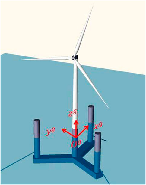
FIGURE 1. Schematic of 10 MW semisubmersible FOWT system (Zhao et al., 2019).
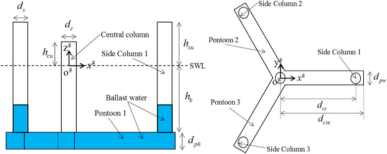
FIGURE 2. Layout of the 10 MW semisubmersible platform.
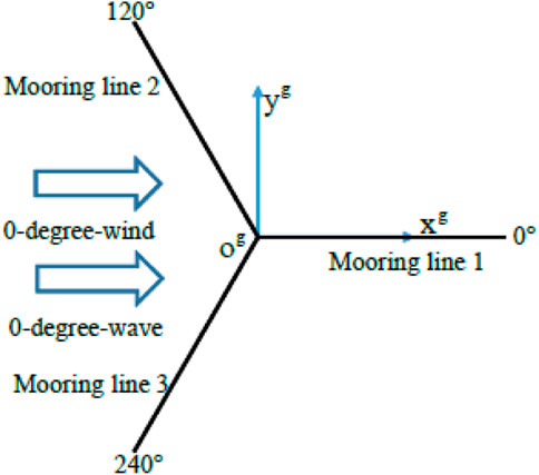
FIGURE 3. Arrangement of the mooring lines.
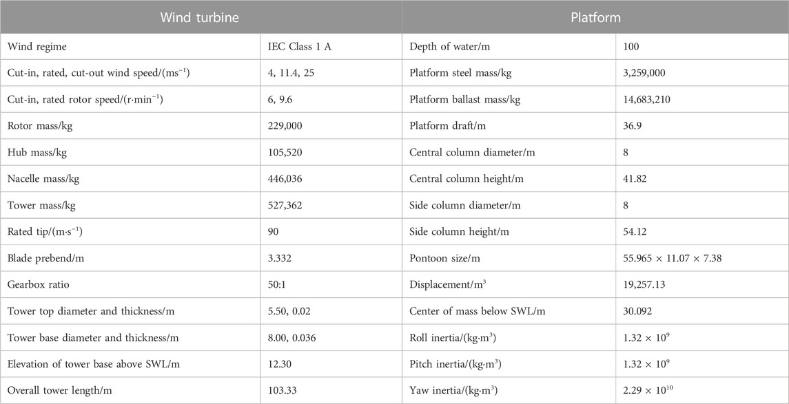
TABLE 1. Main design parameters of the 10 MW FOWT.
The wind turbine is DTU’s 10 MW reference wind turbine (RWT), which is designed by upscaling the National Renewable Energy Laboratory (NREL) 5 MW RWT. Compared with the NREL 5 MW RWT, the DTU 10 MW RWT has longer blades and a different drivetrain system to adapt to a medium speed. It is also a conventional three-blade upwind wind turbine. The servo control system is redesigned using the GSPI control method (Jonkman et al., 2009), which can realize the safe operation of a floating wind turbine. The detailed design process of the servo control system is presented in Section 3.2.
To adapt to the medium water depth (100 m), the mooring system was redesigned for the 10 MW FOWT. Three catenary mooring lines were adopted to fix the FOWT. The arrangement of the mooring system is shown in Figure 4, and its properties are listed in Table 2.
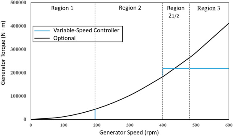
FIGURE 4. Torque-versus-speed response of the variable-speed controller.

TABLE 2. Properties of the mooring system.
The normal operation of a 10 MW FOWT cannot be separated from an effective servo control system. The 10 MW FOWT is a wind turbine with a variable speed and collective pitch control. Its control mode mainly includes torque control below the rated wind speed, and blade pitch control above the rated wind speed.
The generator torque is a tabulated function of the filtered generator speed composed of four control regions: 1, 2, 2 ^ 1/2, and 3 (Figure 4). In Region 1 of Figure 4, the torque of the generator is zero, no power is obtained from the wind, and the wind speed is used to start the wind turbine generator. In Region 2, the wind speed is captured to optimize the power, and the torque of the generator is proportional to the square of the filtered generator speed. Region 2^1/2 is the transition region between Regions 2 and 3. In Region 3, a constant torque is applied to avoid negative damping of the FOWT.
In Region 3, collective blade pitch control is implemented to ensure the safety of the FOWT. The design of the blade pitch controller adopts the gain scheduling proportional integral (GSPI) control method, which was the earliest used method to design the NREL 5 MW wind turbine by Jonkman (Jonkman et al., 2009). The PID controller is set by measuring the deviation between the current rotor speed and the base rotor speed to establish the relationship between the pitch angle and the rotation speed disturbance, and the corresponding motion in Eq. 8, is obtained. The motion equation is derived from Eqs 9, 10 as follows.
The idealized PID-controlled rotor speed error responding as a second-order system with natural frequency
where TAero denotes the aerodynamic torque, TGen denotes the generator torque, n denotes the high-speed to low-speed gearbox ratio, IRotor denotes the rotor inertia, IDrive denotes the drivetrain inertia,
The GSPI control method is adopted by ignoring the derivative gain and negative damping from the generator-torque controller.
Using the GSPI control method, the linear relationship between pitch sensitivity and blade pitch angle is used to realize the design of a variable-blade-pitch controller with unsteady PI gain. According to a linearization analysis in FAST using AeroDyn (Moriarty and Hansen, 2005), the sensitivity of the pitch angle at each wind speed can be obtained. To avoid the influence of the wind turbine wake on the calculation results, it is necessary to freeze the wake during the linearization procedure. The sensitivity of the aerodynamic power of the DTU 10 MW to the blade pitch is shown in Table 3. And the best-fit line of pitch sensitivity in Region 3 The least-square linear fitting for aerodynamic sensitivity of pitch angle is obtained as shown in Figure 5.

TABLE 3. Sensitivity of aerodynamic power to blade pitch in Region 3.
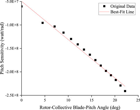
FIGURE 5. Best-fit line of pitch sensitivity in Region 3 The least-square linear fitting for aerodynamic sensitivity of pitch angle.
For 10 MW land-based and offshore bottom-fixed wind turbine, constant power control is adopted, for which the
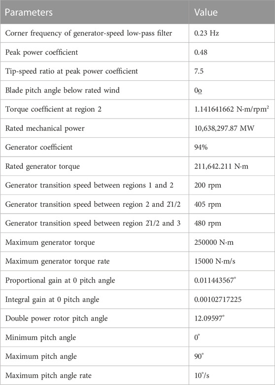
TABLE 4. 10 MW FOWT control system properties.
In this study, the numerical tool used to model the coupled behavior of the DTU 10 MW FOWT in the time domain is based on the hydrodynamic calculation program ANSYS/AQWA, the wind turbine load calculation program FAST, compiled MATLAB modules.
ANSYS/AQWA uses wave analysis methods based on diffraction theory and Morrison’s theory to calculate the frequency-domain hydrodynamic coefficients of the 10 MW FOWT braceless semi-submersible platform, including added mass, potential damping, and first-order wave exciting forces. These hydrodynamic coefficients and wave transfer functions must be converted to the WAMIT (Lee, 1995) format using the MATLAB program, which can be recognized by FAST for full coupling analysis in the time domain. In the study, the coupled numerical model of the 10 MW FOWT is established in FAST, which was a coupled aero-hydro-servo-elastic simulation tool developed by NREL. In the coupled analysis, the elastic deformations of the rotor blades of 10 MW FOWT were analyzed using multi-body dynamics theories in ElastoDyn module in FAST, and the corresponding aerodynamic loads were calculated in AeroDyn module according to blade element momentum theory. The mooring line was modeled and solved in MoorDyn module. According to the servo control system designed in the previous section, the controller model was built in ServoDyn module.
To analyze the coupling of the entire motion under the combined action of wind and waves, the free decay motion test of the entire DTU 10 MW FOWT must first be carried out using FAST. This test primarily considers the motion direction of the surge, pitch, and heave, which are important for the motions of a semi-submersible FOWT. The natural frequency of these motions can be obtained using the Fourier transform of the time histories of the free-decay motion test, as shown in Figure 6 and listed in Table 5.
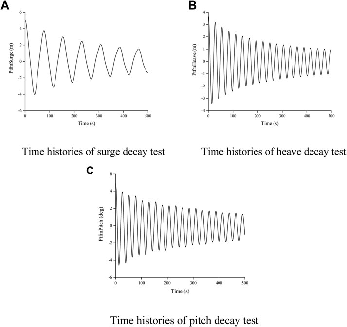
FIGURE 6. Free decay motion simulations. (A) Time histories of surge decay test; (B) Time histories of heave decay test; (C) Time histories of pitch decay test.
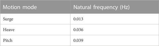
TABLE 5. Natural frequencies of 10 MW FOWT.
Six environmental conditions (ECs) are defined to study the coupled dynamic response characteristics of the 10 MW FOWT system (including the servo control system) under turbulent winds and irregular waves, as listed in Table 6. EC3–4 are used to consider the dynamic response characteristics of the 10 MW FOWT under the excitation of turbulent wind and irregular waves; EC4 is an operation with a normal wind profile (NWP) without turbulence, which is used to analyze the excitation of irregular waves on FOWT motion and to contrast with EC3. EC1 is an operation below the rated wind speed, EC2 is an operation above the rated wind speed, and EC5 is a storm condition in which the wind turbine remains idle. EC3–6 are used to study the performance of the 10 MW FOWT over the entire range of wind speeds. The turbulence wind is generated by TurbSim (Moriarty and Hansen, 2005; Jonkman, 2009) based on the Kaimal spectrum for IEC Class A, as suggested in (International Electrotechnical Commission, 2005), with a normal turbulence model (NTW) and the power law with an exponent of 0.14 (International Electrotechnical Commission, 2009), which is used in a wind shear model. The wind speed region is 200 × 200 m with a vertical plane of 67 × 67 points, and the time step generated by the three-dimensional turbulent wind fields is 0.05 s. The wave spectrum adopts the Jonswap spectrum, which includes two main parameters: the peak period (Hs) and significant wave height (Tp). The wind and waves are in the same direction, heading in the positive direction of the X-axis.
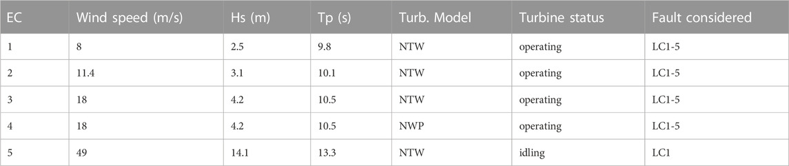
TABLE 6. Definitions of the environmental and fault conditions.
The five faults are defined as follows.
LC1: Fault-free condition.
LC2: Blade 1 pitch actuator is stuck at 1,500 s, blades 2, and 3 continue to operate.
LC3: Blade 1 pitch actuator is stuck at 1,500 s, and the controller reacted after 0.1 s. Blades 2 and 3 are feathering to shut down the FOWT with grid loss.
LC4: Blade 1 pitch actuator runaway at 1,500 s and feather to 90°, blades, 2 and 3 continue to operate.
LC5: The grid is disconnected at 1,500 s and all three blades feather to 90 to shut down the FOWT.
LC1 represents the normal operating state. LC2–3 represent a faulty operating condition in which a blade seizes. LC4 represents the fault condition in which blade runaway occurs. LC5 represents the fault condition in which grid loss occurs.
To analyze the excitation law of turbulent wind and irregular waves on the 10 MW FOWT, a time-domain simulation is performed for the surge, heave, pitch, generator power, and blade pitch angle of the FOWT under the action of turbulent wind (EC3) and constant wind (EC4) with an irregular wave. The duration of each simulation was 2,500 s. To avoid the influence of the transient response caused by the initial condition setting, the last simulation duration of 500 s is taken.
As shown in Figure 7, the turbulent wind greatly affects the surge and pitch platform motion, the heave platform motion is affected by the turbulent wind to a certain extent, and the turbulent wind drives the blade pitch controller to change the blade pitch angle because the constant torque control mode is adopted; the generator power fluctuates around the rated power. Based on the time history of the pitch, surge, and heave motions, they are effectively controlled. To further analyze the excitation law of turbulent wind and irregular waves on the 10 MW FOWT under the servo control system, a frequency domain analysis is conducted.
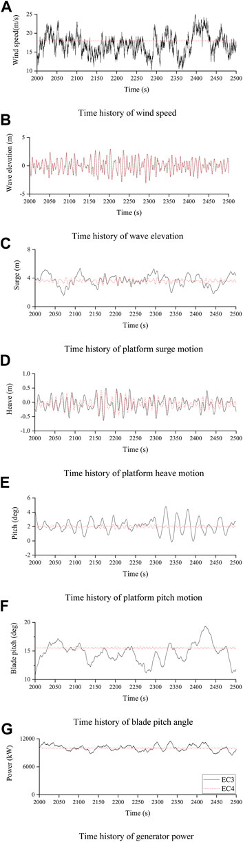
FIGURE 7. Time domain response of main parameters of 10 MW FOWT. (A) Time history of wind speed; (B) Time history of wave elevation; (C) Time history of platform surge motion; (D) Time history of platform heave motion; (E) Time history of platform pitch motion; (F) Time history of blade pitch angle. (G) Time history of generator power.
According to the motion in the direction of the surge, pitch, and heave analyzed by the power spectrum as shown in Figure 8, the surge, pitch, and heave motion resonance frequencies increase under the influence of turbulent wind. Wave frequency motion is not affected because the energy of the turbulence wind is mainly concentrated in the low-frequency area, which shows that the low-frequency surge, pitch, and heave motion of the 10 MW FOWT are mainly excited by the turbulence wind. Wave excitation wave frequency surge, pitch, and heave motion, in which the surge and pitch motions are dominated by low frequency, and the heave motion is affected by turbulence wind and irregular waves. Simultaneously, considering the large structure size at the surface line of the ultra-large semi-submersible platform, the natural period of the heave motion is closer to the high-energy region of the wave spectrum, and the heave response may be greatly excited by the wave load. To avoid the occurrence of this adverse phenomenon, measures such as increasing the draft of the semi-submersible platform of the ultra-large FOWT, setting up the structure of the pendant plate, or setting up the fast mass on the mooring can be considered to improve the heave motion performance of the platform. There is an obvious coupling relationship between the pitch motion and surge motion, but there is no obvious coupling relationship between the heave motion and other motions.
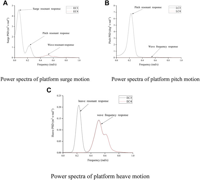
FIGURE 8. Power spectra of motions of 10 MW FOWT. (A) Power spectra of platform surge motion; (B) Power spectra of platform pitch motion; (C) Power spectra of platform heave motion.
Structural load is very important for the safety of the FOWT. The structural response mainly considers the fore-aft tower top bending moment and the fore-aft tower base bending moment. According to the analysis of the time-domain simulation results as shown in Figure 9, it can be seen that the tower top bending moments are more sensitive to turbulence wind load than to irregular wave load, which is mainly affected by turbulent wind. Meanwhile, the tower base bending moments are affected by both turbulence wind and irregular wave loads. These results are closely related to the location of the tower structure.

FIGURE 9. Time domain response of structural loads of 10 MW FOWT. (A) Time history of tower top bending moment; (B) Time history of tower base bending moment.
According to the mooring line distribution, mooring #1 is arranged along the positive X direction, which leads to a minimum mooring tension, and mooring #2 and mooring #3 are arranged symmetrically about the x-axis. The simulation results of the three mooring lines are compared. Mooring #1 has a minimum tension force because of the thrust of the rotor, and is greatly affected by turbulent wind. The tension forces on moorings #2 and #3 are evidently different because of the influence of the gyro effect on aerodynamics; mooring #3, which is arranged to the right of the wind direction, is more susceptible to turbulent winds. Power spectrums of surge motion and mooring lines #1, #2, and #3 are shown in Figure 10. The similar trend indicates that the mooring line tension is directly influenced by the surge motion and is mainly excited by the low-frequency turbulent wind during operation.
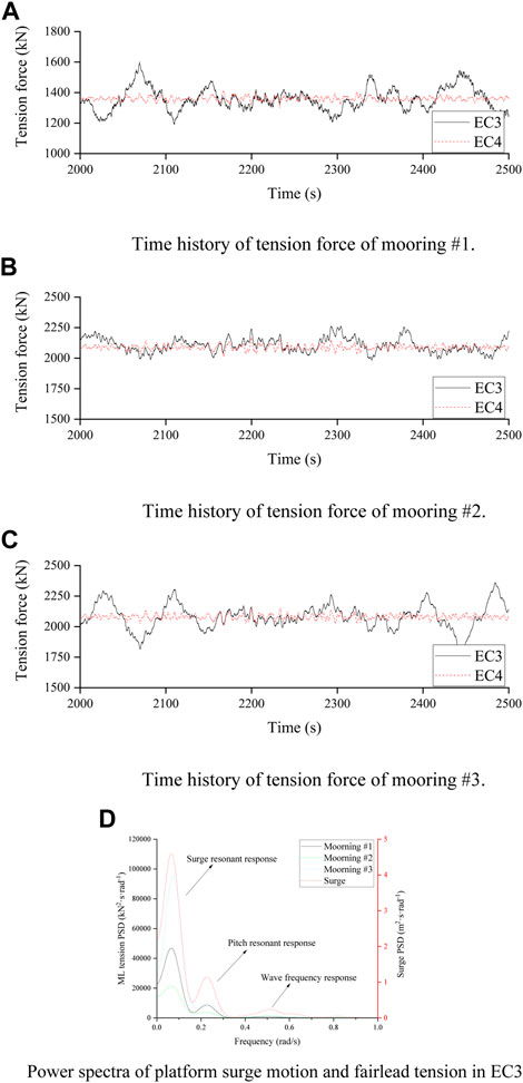
FIGURE 10. Time domain response of mooring line of 10 MW FOWT. (A) Time history of tension force of mooring #1. (B) Time history of tension force of mooring #2. (C) Time history of tension force of mooring #3. (D) Power spectra of platform surge motion and fairlead tension in EC3.
A statistical analysis of the 10 MW FOWT under different combined wind and wave environmental conditions was performed. The results are shown in Figure 11. According to the results, platform surge and pitch exhibit similar patterns. The maximum surge and pitch motions both occur at the rated wind speed. At the rated wind speed, the FOWT receives the maximum aerodynamic thrust, which results in the largest mean surge and pitch. In the EC5 case, the blades feather and the FOWT is mainly excited by irregular waves. The surge and pitch motions are relatively small, whereas the heave motion is the highest. It is shown that the surge and pitch motions are mainly stimulated by turbulent wind but less by irregular waves, whereas the heave motion is mainly influenced by irregular waves but less by turbulent wind. The mooring line tension force follows the same pattern as the surge motion, and the top bending and base bending moments have a similar pattern to the surge and pitch motions, which illustrates that the FOWT structural load is closely related to the platform motion.
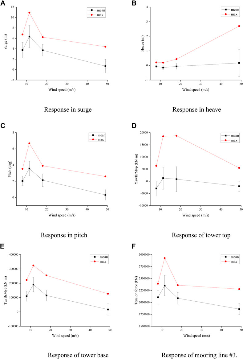
FIGURE 11. Time statistical analysis of 10 MW FOWT. (A) Response in surge; (B) Response in heave; (C) Response in pitch; (D) Response of tower top; (E) Response of tower base; (F) Response of mooring line #3.
To analyze the dynamic response of the 10 MW FOWT under fault conditions, a time-domain simulation was performed for different fault conditions. Because the occurrence of the fault condition in FOWT is random, the offshore wind turbine standards suggest that 12 simulations with different wind and wave profiles with a 10-min duration must be carried out to observe power production and fault cases (Lee, 1995). The duration of each simulation was 2,500 s. To avoid the influence of the transient response caused by the initial condition setting, the last simulation duration of 1,500 s was taken.
When the FOWT experiences a fault and emergency shutdown, the blade pitch rate (Pr) has a significant influence on the aerodynamic load on the blade and rotor speed. Therefore, it is necessary to further discuss the velocity of the 10 MW FOWT under fault conditions.
For a comprehensive analysis of the effect of blade pitch rate during emergency shutdown for 10 MW FOWT, the pitch rate range is defined as [2°/s, 14°/s]. The maximum rotor speed during the downtime caused by the fault and the duration of the FOWT shutdown state (which is observed when the FOWT rotor speed is reduced to less than 3 rpm) are the main indicators to be considered. The maximum rotor speed and shutdown duration of EC4-LC3 and LC5 under the action of uniformly distributed blade pitch rates of 2, 4, 6, 8, 10, 12, and 14°/s were compared, as shown in Figure 12 in the updated manuscript.
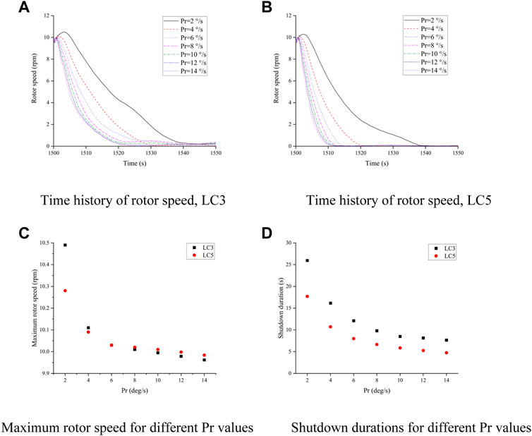
FIGURE 12. Maximum rotor speed and shutdown duration. (A) Time history of rotor speed, LC3; (B) Time history of rotor speed, LC5; (C) Maximum rotor speed for different Pr values; (D) Shutdown durations for different Pr values.
LC3 and LC4 are both shutdown conditions under the fault FOWT. The difference is that blade #2 cannot pitch normally because its pitch actuator is blocked. The FOWT can only rely on the remaining blades to achieve aerodynamic breaking in the LC3 case, while the FOWT can maximize aerodynamic braking by feathering three blades in the LC4 case; therefore, the aerodynamic braking effect of LC4 is the best and the shutdown duration is relatively short. The shutdown duration and maximum rotor speed under both fault conditions decrease with an increasing in the pitch rate, and the shutdown duration is very sensitive to the pitch rate. The shutdown duration under 2°/s is about 3.7 times that under 14°/s. Therefore, to effectively avoid the adverse effect of rotor overs peed and shut down the FOWT as quickly as possible, a larger pitch rate is recommended. For the 10 MW FOWT, the maximum pitch rate is designated as 10°/s (BAK et al., 2012).
As a transient response, the response caused by the fault condition of the 10 MW FOWT may exceed the response amplitude under normal or extreme sea conditions and become the control load that determines the safety of the structure. Therefore, it is necessary to conduct statistics on the responses under different fault conditions and compare them with the results under different sea conditions.
Because the response under some fault conditions (particularly LC3 and LC4) is random and closely related to the value of the pitch angle when the fault occurs, it is necessary to choose an appropriate analysis method. In this study, 30 groups with different wind and wave seeds for 1,000-s simulation are selected, and the average value of the maximum absolute value in each simulation is calculated to determine the condition where the maximum value occurred.
According to the statistical results of response amplitude listed in Table 7, it can be concluded that.
(1) The 10 MW semi-submersible FOWT has the maximum surge and pitch in the LC2 case for the rated wind speed. Compared with the studies of Reference (Bachynski et al., 2013), the 5 MW semi-submersible FOWT has the maximum surge and pitch in the extreme wave condition. The difference in dynamic response is mainly because the 10 MW FOWT has lower motion and structure natural frequency; therefore, in addition to heave response, the turbulent wind excitation of a 10 MW FOWT is much greater than that of the wave excitation. The heave motion mainly reaches the response amplitude under the condition of wind turbine idling under extreme waves, indicating that the heave motion is greatly affected by wave excitation.
(2) The amplitude of the mooring tension occurs in the LC2 case at the rated wind speed owing to the surge motion.
(3) The tower top bending moments are most sensitive to LC5 under EC2 and reach the amplitude, while the tower base bending moments reaches a maximum in the LC2 case at the rated wind speed. The tower top bending moment can represent the shaft loading to a certain extent, which shows that the it is very sensitive to the imbalance of the aerodynamic load.
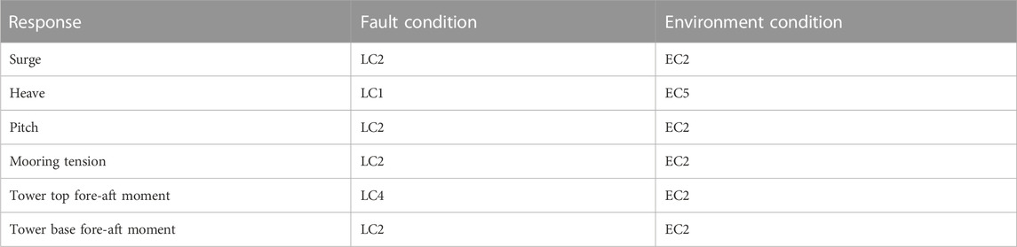
TABLE 7. 10 MW FOWT fault events statistical.
It can be seen that the overall maximum motion, mooring tension, and structural load of the 10 MW semi-submersible FOWT are not only affected by the wind and wave conditions during operation but are also affected by some fault conditions.
The fault condition is essentially a transient process in the time-domain. Therefore, the motion and structural responses caused by faults must be analyzed in the time domain. EC3 is selected as the environmental condition for the simulation when a fault condition occurs. The motion and structural responses of the DTU 10 MW FOWT are different for different fault conditions. The fault conditions are further divided into three categories: stuck pitch actuator (LC2–LC3), pitch actuator runaway (LC4), and grid loss (LC5). For each fault condition category, the 2,500 s simulation is carried out and compared with the normal operating conditions (LC1). The surge, heave, and pitch motions, fore-aft tower top bending moment, fore-aft tower base bending moment, and mooring tension of the 10 MW FOWT are studied, and mooring line #3 is selected because the tension for this mooring line is the maximum of all three mooring lines.
When a blade pitch actuator is stuck, the different actions of the other two blades cause different motions and structural responses. In the LC2 case, the other two blades continue to operate. Although the surge, heave, and pitch motions, tower base bending moment, and mooring tension are not affected, the tower top bending moment becomes much larger than that in normal operation. This phenomenon occurs because of the imbalance of aerodynamic load by the blade seize, which is unfavorable for the safety of the 10 MW FOWT. In the LC3 case, the other two blades feather to shut down the FOWT with grid loss, and the pitch rate is chosen to be 10°/s. As shown in Figure 15. The emergency shutdown of the FOWT causes the thrust on the rotor to decrease suddenly to a negative value. As a result, the FOWT moves along the negative x-axis, causing surge and pitch motion decrease, tower base bending moment decrease, the mooring #2 and #3 tension decrease, and the mooring #1 tension increase. Subsequently, as the thrust decreases, these responses gradually decay to zero. The tower top bending moment produces a very large negative load, which is approximately twice the maximum value during normal operation. By comparing with Figure 13. It is obvious that the shock load on the top of the tower is mainly caused by an imbalance in the aerodynamic load due to the blade seize. The impact of the heave response under LC2 and LC3 is very small and depends mainly on the wave excitation.
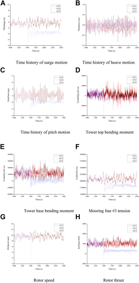
FIGURE 13. Pitch actuator stuck fault condition. (A) Time history of surge motion; (B) Time history of heave motion; (C) Time history of pitch motion; (D) Tower top bending moment; (E) Tower base bending moment; (F) Mooring line #3 tension; (G) Rotor speed; (H) Rotor thrust.
In addition, by combining the statistics of the response maxima in the previous section, it can be seen that the angle at which the blade seize occurs has a significant effect on the motion and structural response. When the stock angle is smaller, the stuck blade is subjected to more aerodynamic loads, which makes the rotor more imbalanced.
When a blade pitch actuator runaway occurs, the rotor speed gradually decreases to zero because of the loss of aerodynamic torque, as shown in Figure 14. When this type of fault occurs, the pitch angle of the fault blade feathers to 90°, which makes the other two normal blades pitch to 0° to try to restore the aerodynamic torque; however, the aerodynamic torque on the blade is still unable to drive the rotor rotation, and as a result, the FOWT finally shuts down. In this fault condition, the surge, heave, and pitch motions, tower base bending moment, and the mooring tension of the FOWT decrease with the reduction in rotor thrust; however, owing to the imbalance of aerodynamic loads on the rotor, the tower top bending moment produces a very large positive value and a negative value, which is approximately twice the maximum during normal operation. If the FOWT is operated under such conditions, the safety of the structure is significantly affected, especially the tower top bending moment. The heave motion of the FOWT is less affected by this fault condition.
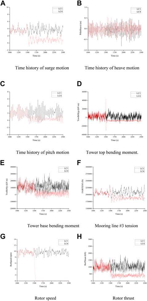
FIGURE 14. Pitch actuator runaway fault condition. (A) Time history of surge motion; (B) Time history of heave motion; (C) Time history of pitch motion; (D) Tower top bending moment; (E) Tower base bending moment; (F) Mooring line #3 tension; (G) Rotor speed; (H) Rotor thrust.
This fault condition considers the accidental loss of the power grid at a certain time. The FOWT is shut down after detecting the signal of grid loss, and the three blades feather to 90° for aerodynamic torque braking. The pitch rate is chosen to be 10°/s. As shown in Figure 15. The emergency shutdown of the FOWT causes the thrust on the rotor to suddenly decrease to a negative value, as in the LC3 case. However, in this case, the aerodynamic load of the rotor is distributed over three blades on average. As a result, there is no imbalance in the aerodynamic loads on the rotor and a large shock load on the top of the tower. The surge, heave and pitch motion, tower base bending moment, and mooring tension of the FOWT decrease with the reduction in rotor thrust, and the heave motion of the FOWT is largely unaffected by this fault.
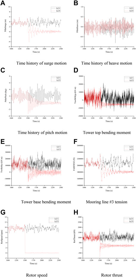
FIGURE 15. Grid loss fault condition. (A) Time history of surge motion; (B) Time history of heave motion; (C) Time history of pitch motion; (D) Tower top bending moment; (E) Tower base bending moment; (F) Mooring line #3 tension; (G) Rotor speed; (H) Rotor thrust.
In this study, a tower, semi-submersible platform, mooring line system, and servo control system were designed for the DTU 10 MW RWT to investigate the coupling dynamic response characteristics under the combined action of wind and waves. Based on the programs ANSYS/AQWA, FAST, and MATLAB/Simulink, a numerical tool for a fully coupled dynamic response analysis of a 10 MW FOWT was developed. To better understand the response characteristics and laws of the 10 MW FOWT under various conditions, different conditions were discussed, including operational, extreme, and fault situations, and the following conclusions could be drawn from this study.
(1) During normal operation of the 10 MW FOWT, the turbulent wind stimulates low-frequency surge, pitch, and heave motion, while an irregular wave stimulates wave-frequency surge, pitch, and heave motion. The surge and pitch motions are dominated by low-frequency excitation, whereas the heave motion is dominated by wave-frequency excitation. Therefore, the surge and pitch motions are significantly affected by turbulent wind, whereas the heave motion is mainly affected by irregular waves. There is an evident coupling relationship between the surge and pitch motions, whereas there is no coupling relationship between the heave and other motions.
(2) The tower top bending moment reflects both aerodynamic loads and loads caused by rotor inertia and is mainly affected by turbulent wind. The tower base bending moment is mainly caused by the thrust on the rotor and the wave excitation force on the platform. Therefore, the tower base bending moment is affected by both turbulence wind and irregular waves.
(3) The mooring line tension is directly influenced by the surge motion and is mainly excited by low-frequency turbulent winds during operation. Because of the influence of the gyro effect of aerodynamic loads, the mooring line arranged to the right of the wind direction is more susceptible to turbulent winds.
(4) According to the statistical analysis under the combined action of different winds and waves of the 10 MW FOWT, the mean value and amplitude of the surge and pitch motions, the tower base bending moment, and mooring tension reach their maximum values under the rated wind speed and exhibit maximum fluctuation. The mean value and amplitude of the heave motion reach a maximum under storm conditions where the wind turbine is idling.
(5) To effectively avoid the adverse effect of rotor overspeed on the 10 MW FOWT and shut down the FOWT as quickly as possible, a maximum pitch rate of 10°/s should be selected during an emergency shutdown caused by a fault.
(6) Different fault conditions can cause different motions and structural responses, and the tower top bending moment is significantly affected by the imbalance in the aerodynamic load, which produces a very large shock load when the blade actuator is stuck and when runaway occurs. The surge and pitch motions, tower base bending moment, and mooring tension of the FOWT are affected by different fault conditions to varying degrees. The heave motion is generally barely affected by the fault conditions.
In general, we studied the response characteristics and laws of a semi-submersible-type 10 MW FOWT under operational, extreme, and fault situations, which can provide a reference for the design and analysis of ultra-large FOWTs in the future. The analysis of the dynamic characteristics under different conditions can effectively guide the operation safety of the 10 MW FOWT over its entire lifetime. However, there are still many issues to be studied in the future. For example, a simple and constant blade pitch rate was adopted for the emergency shutdown in this study. Complex and multi-stage emergency shutdown strategy may be more advantageous for motion and structural loads of 10 MW FOWT. The fault dynamic characteristics of wind-wave misalignment should be analyzed further. The imbalance in aerodynamic loads caused by the blade actuator stuck and runaway has a significant effect on the transmission shaft, and the dynamic response of the transmission system in the fault condition must be studied by establishing a more accurate transmission shaft model. Moreover, owing to the simplifications of pitch actuators in the established coupled numerical model of FOWT, the limitations on the investigation of pitch actuator performance should be pointed out. In further studies, the coupled numerical model shall be developed by introducing additional pitch actuators degrees of freedom, and the influence of pitch actuators shall be investigated.
The raw data supporting the conclusion of this article will be made available by the authors, without undue reservation.
Conceptualization: DH. Methodology: DH and YL. Investigation: BW. Writing—first draft preparation, writing, review and editing: DH, WW, XL, and XS. Visualization: WW, XL, and XS. Supervision and funding acquisition: WW and XL. WW, XL, and XS set the objectives of the research, provided guidance for the research, and revised the paper. All authors contributed to the article and approved the submitted version.
The authors acknowledge support from the Open Fund of Key Laboratory of Far-shore Wind Power Technology of Zhejiang Province (ZOE2020004), and the National Natural Science Foundation of China (Grant Nos. 52071301, 52001052).
Authors YL and BW were employed by the company Power China Huadong Engineering Corporation Limited.
The remaining authors declare that the research was conducted in the absence of any commercial or financial relationships that could be construed as a potential conflict of interest.
All claims expressed in this article are solely those of the authors and do not necessarily represent those of their affiliated organizations, or those of the publisher, the editors and the reviewers. Any product that may be evaluated in this article, or claim that may be made by its manufacturer, is not guaranteed or endorsed by the publisher.
Bachynski, E. E., Etemaddar, M., Kvittem, M. I., Luan, C., and Moan, T. (2013). “Dynamic analysis of floating wind turbines during pitch actuator fault, grid loss, and shutdown,” in 10th deep sea offshore wind R&D conference, Trondheim, Feb 2013.
Bak, C., Bitsche, R., and Yde, A. (2012). Light rotor: The 10-MW reference wind turbine//EWEA 2012-European. Copenhagen, Denmark: Wind Energy Conference & Exhibition.
Cai, Y., Zhao, H., Li, X., and Liu, Y. (2023). Effects of yawed inflow and blade-tower interaction on the aerodynamic and wake characteristics of a horizontal-axis wind turbine. Energy 264, 126246. doi:10.1016/j.energy.2022.126246
Chaaban, R., Ginsberg, D., and Fritzen, C. P. (2014). “Structural load analysis of floating wind turbines under blade pitch system faults,” in Wind turbine control and monitoring. Advances in industrial control. Editors N. Luo, Y. Vidal, and L. Acho (Cham: Springer).
Etemaddar, M., Gao, Z., and Moan, T. (2012). “Structural load analysis of a wind turbine under pitch actuator and controller faults,” in The science of making torque from wind (Oldenburg, Germany: IAEA).
Han, Y., Le, C., Ding, H., Cheng, Z., and Zhang, P. (2017). Stability and dynamic response analysis of a submerged tension leg platform for offshore wind turbines. Ocean. Eng. 129, 68–82. doi:10.1016/j.oceaneng.2016.10.048
Hansen, M. H., and Henriksen, L. C. (2013). Basic DTU wind energy controller. Denmark: DTU Wind Energy E.
International Electrotechnical Commission (2005). Wind turbines: Part 1: Design requirements. Switzerland: International Electrotechnical Commission. IEC61400-1.
International Electrotechnical Commission (2009). Wind turbines: Part 3: Design requirements for offshore wind turbines. Switzerland: International Electrotechnical Commission. IEC61400-3.
Islam, M. T. (2016). Design, numerical modelling and analysis of a semi-submersible floater supporting the DTU 10 MW wind turbine/. Norway: Norwegian University of Science and Technology.
Jiang, Z., Karimirad, M., and Moan, T. (2014). Dynamic response analysis of wind turbines under blade pitch system fault, grid loss and shut down events. Wind Energy 17 (9), 1309–1409.
Jonkman, B. J. (2009). TurbSim user’s guide: Version 1.50. Colorado: National Renewable Energy Laboratory. NREL/TP-500-46198.
Jonkman, J., Butterfield, S., Musial, W., and Scott, G. (2009). Definition of a 5-MW ReferenceWind turbine for offshore system development. Colorado: National Renewable Energy Laboratory. NREL/TP-500-38060.
Jonkman, J. M. (2007). “Dynamics modeling and loads analysis of an offshore floating wind turbine,”. Technical Report.
Jonkman, J. M., and Buhl, M. L. (2005). FAST user’s guide. Colorado: National Renewable Energy Laboratory. NREL/EL-500-38230.
Karimirad, M., and Michailides, C. (2019). Fault condition effects on the dynamic response of V-shaped offshore wind turbine. J. Mar. Sci. Technol. 24 (1), 34–45. doi:10.1007/s00773-018-0529-3
Larsen, T. J., and Hanson, T. D. (2007). A method to avoid negative damped low frequent tower vibrations for a floating, pitch controlled wind turbine. J. Phys. Conf. Ser. 75, 012073. The Second Conference on The Science of Making Torque from Wind. doi:10.1088/1742-6596/75/1/012073
Lee, C. H. (1995). WAMIT theory manual. Cambridge: Massachusetts Institute of Technology, Department of Ocean Engineering.
Luan, C. (2018). Design and analysis for a steel braceless semi-submersible hull for supporting a 5-MW horizontal axis wind turbine. Washington: ASME.
Moriarty, P. J., and Hansen, A. C. (2005). AeroDyn theory manual. Golden, CO (US): National Renewable Energy Lab.
Shi, W., Zhang, L., Karimirad, M., Michailides, C., Jiang, Z., and Li, X. (2023). Combined effects of aerodynamic and second-order hydrodynamic loads for floating wind turbines at different water depths. Appl. Ocean Res. 130, 103416. doi:10.1016/j.apor.2022.103416
Tian, X. S. (2016). Design, numerical modelling and analysis of a TLP floater supporting the DTU 10 MW wind turbine. Norway: Norwegian University of Science and Technology.
Wilkinson, M., and Hendriks, B. (2011). “Reliability focused research on optimizing wind energy systems design, operation and maintenance: Tools, proof of concepts, guidelines & methodologies for a new generation,” Tech rep, Reliawind.
Xue, W. F. (2016). Design, numerical modelling and analysis of a spar floater supporting the DTU 10 MW wind turbine. Norway: Norwegian University of Science and Technology.
Zhang, L., Shi, W., Zeng, Y., Michailides, C., Zheng, S., and Li, Y. (2023). Experimental investigation on the hydrodynamic effects of heave plates used in floating offshore wind turbines. Ocean. Eng. 267, 113103. doi:10.1016/j.oceaneng.2022.113103
Zhao, Z., Li, X., Wang, W., and Shi, W. (2019). Analysis of dynamic characteristics of an ultra-large semi-submersible floating wind turbine[J]. J. Mar. Sci. 7(6), 169.
Zhao, Z., Shi, W., Wang, W., Qi, S., and Li, X. (2021). Dynamic analysis of a novel semi-submersible platform for a 10 MW wind turbine in intermediate water depth. Ocean. Eng. 237, 109688. doi:10.1016/j.oceaneng.2021.109688
Keywords: floating wind turbine, torque control, pitch control, fully coupled analysis, fault conditions
Citation: Li Y, Han D, Wang B, Wang W, Li X and Su X (2023) Coupled dynamic characteristics of 10 MW semi-submersible offshore wind turbine under typical operation, extreme, and fault conditions. Front. Energy Res. 11:1140792. doi: 10.3389/fenrg.2023.1140792
Received: 09 January 2023; Accepted: 11 April 2023;
Published: 09 May 2023.
Edited by:
Radu Saulescu, Transilvania University of Brașov, RomaniaReviewed by:
Bofeng Xu, Hohai University, ChinaCopyright © 2023 Li, Han, Wang, Wang, Li and Su. This is an open-access article distributed under the terms of the Creative Commons Attribution License (CC BY). The use, distribution or reproduction in other forums is permitted, provided the original author(s) and the copyright owner(s) are credited and that the original publication in this journal is cited, in accordance with accepted academic practice. No use, distribution or reproduction is permitted which does not comply with these terms.
*Correspondence: Dongdong Han, aGFuZGRAbWFpbC5kbHV0LmVkdS5jbg==
Disclaimer: All claims expressed in this article are solely those of the authors and do not necessarily represent those of their affiliated organizations, or those of the publisher, the editors and the reviewers. Any product that may be evaluated in this article or claim that may be made by its manufacturer is not guaranteed or endorsed by the publisher.
Research integrity at Frontiers
Learn more about the work of our research integrity team to safeguard the quality of each article we publish.