 Chang Zhou
 Yingqi Liao3
 Kaifeng Zhang
- 1Key Laboratory of Measurement and Control of CSE, School of Automation, Southeast University, Nanjing, Jiangsu, China
- 2Renewable Energy Research Center, State Key Laboratory of Operation and Control of Renewable Energy and Storage Systems, China Electric Power Research Institute, Nanjing, Jiangsu, China
- 3State Grid Nanjing Power Supply Company, Nanjing, Jiangsu, China
The virtual inertia technology of DGs (Distributed Generations) can provide inertia and damping support for the power system by imitating the traditional synchronous machine. However, the inherent delay problems around the communication and process links of the virtual inertia control will make an impact on the fast support effect. In this paper, the virtual inertia based hierarchical control scheme considering communication delay for distributed generations integration systems is proposed. The hierarchical control architecture including the PQ primary control and the virtual inertia based secondary control method which can realize the optimal power utilization and certain frequency support under the situation of communication signal delay at the same time. Firstly, the basic hierarchical control scheme for distributed generations and corresponding small signal modeling considering communication delay are presented. Then to enhance the inertia support ability of the distributed generation integration system, an improved hierarchical control strategy considering communication delay is designed based on the robust passivity method to compensate the equivalent delay disturbance. Finally, the effectiveness verification of the proposed control is carried out with the simulation cases in PSCAD platform.
1 Introduction
With the rapid development of distributed generations (DGs) such as wind and photovoltaic, the inertia level of power system is greatly reduced, which seriously weakens the inertia support and frequency stabilization ability of the system. Nevertheless, the frequency stability of power system with high proportion DG integration can be significantly improved by making full use of the flexible adjustment ability of large-scale DGs (Liu et al., 2019; Razavi et al., 2019; Quan et al., 2020). As the energy storage system has the characteristics of stable performance, flexible control and fast response, some studies have used the energy storage system to assist the frequency regulation process, but the high cost and low life of the energy storage system are its main shortcomings (Guan, 2022; Guo et al., 2023). Besides, the DGs can participate in the frequency modulation of power grid through the direct control of the DG output power (Zhang et al., 2021), which directly controls the DGs to respond when the frequency is adjusted. This method makes the DGs unable to work at its optimal power point, which is equivalent to increasing the investment of distributed power supply.
In order to improve the stability of DG integration system, researchers are trying to find a suitable control method of power electronic converter to improve the stability of power system. It is a promising method to control the power electronic converter to have the dynamic characteristics of the traditional synchronous machine, which is called the virtual inertia technology (Beck and Hesse, 2007; Zhong and Weiss, 2011). The virtual inertia technology uses the mathematical model of the traditional synchronous machine to calculate the reference value of the inverter current and then controls the output current. The DG integration system under this control method can provide virtual inertia and damping for the power system by imitating the traditional synchronous machine. In (Kheshti et al., 2022), a novel Gaussian distribution-based inertial control scheme that can improve the frequency nadir without rotor speed over-deceleration is proposed. In (Guo et al., 2022), an inertial phase-locked loop is proposed for grid-connected converter to achieve fast frequency support which is analogous to the motion equation of synchronous generator. In (Yang et al., 2022), a fast frequency response strategy of a DFIG is proposed based on variable power point tracking control to boost the frequency support capability with grid-friendly rotor speed recovery. In (Xiong et al., 2021), a frequency trajectory planning based strategy is developed to improve frequency stability of droop-controlled inverter-based standalone power systems. To remain the basic structure of the DG control system, the power tracking scheme is adopted in this paper, which introduces the rate of change of frequency to the active power control loop of DG to provide inertia support by adjusting the active power command when the system frequency changes (Meng et al., 2019; Sun et al., 2020).
However, the virtual inertia control technology is realized by using digital control technology which includes the instruction generation and control realization processes. Hence the inherent delay problems around the communication and process links will make an impact on the fast frequency support effect (Liu et al., 2015; Yuan et al., 2022). According to (Vafamand et al., 2019; Lian et al., 2021), the time delays in digital signal may compromise the integrity and timeliness of the inertial support of the DGs and can be up to hundreds of milliseconds. From the point of view of synchronizing machine simulation, the time delay in the virtual inertia control is expected to be as small as possible. And too much large control delay may even make the system becomes unstable in severe cases (Nan et al., 2018). To handle this problem, the Rekasius substitution is used in (Suud et al., 2022) to compute the stability delay margin of an islanded micro-grid with virtual inertia and constant communication delay. Reference (Yang et al., 2019a) intends to reveal that the effects of delay, which are caused by frequency measurements and DC-link voltage regulation during the inertia emulation, are non-negligible in small-scale low inertia power systems with virtual inertia control implementations. In (Yang et al., 2019b), a detailed analysis of the effect of time-delays on virtual inertia control is presented which reveals that instability will happen when the virtual inertia is greater than the existing power system inertia regardless of time-delays. In (Haldar et al., 2022), a delay based control strategy for emulation of virtual inertia in inverters operating in islanded operation mode is presented. Most of the existing literature relies on classical control theory to analyze the delay problem of a certain part of the control system, but there is a lack of delay modeling and suppression techniques including the control link of the system. Since the virtual inertia control requires fast frequency recovery ability, this paper focuses on the control system modeling and time delay compensation to eliminate the communication signal time-delay influence.
In this paper, the virtual inertia based hierarchical control scheme considering communication delay for DGs integration systems is proposed. The main contributions of the paper can be given as following:
(1) The hierarchical control architecture including the PQ primary control and the virtual inertia based secondary control method is presented which can realize the optimal power utilization and certain frequency support under the situation of communication signal delay at the same time.
(2) To enhance the inertia support ability of the DG integration system with communication delay, the small signal modeling for DGs considering communication delay is presented. Then an improved hierarchical control strategy is designed based on the robust passivity method, which can compensate the equivalent delay disturbance with fast response speed and superior robustness.
The effectiveness verification of the proposed control is carried out with the simulation cases in PSCAD platform, which shows that the proposed virtual inertia control can track the equivalent disturbance caused by time delay and compensate for the delay with superior dynamic response.
2 System structure and hierarchical control architecture for DGs
The systems structure and hierarchical control architecture for DGs are shown in Figure 1. The hierarchical control architecture including the PQ primary control and the virtual inertia based secondary control method is proposed in this paper for DGs. For the DGs, the PQ control mode is adopted in the primary control layer for the optimal utilization efficiency of DGs. In order to make full use of the flexible regulation ability of DGs, the additional virtual inertia control is implemented in the secondary control layer for frequency support of the utility grid. According to the rate of change of frequency, the additional control command can be generated and attached to the active power control loop of DG in the primary PQ control layer to provide inertia support. In the practical operation, due to the communication transmission from the secondary control layer to the controller of each DG unit, the time delay in the hierarchical control scheme is inevitable. Since the secondary virtual inertia control is implemented for fast frequency recovery of the utility grid, the control performance would be significantly impacted by the communication delay, which may bring serious disturbance and reduce the system stability. To eliminate the communication signal time-delay influence, the improved hierarchical control strategy based on virtual inertial considering communication delay is proposed in the following section.
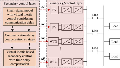
FIGURE 1. Schematic diagram of DG integration system.
3 Hierarchical control strategy for DGs
3.1 Primary PQ control layer
The topology structure of the grid-connected inverter is shown in Figure 2 where C is the DC filter capacitor, Udc is the DC voltage, Lf is the filter inductance of inverter, Lg is the grid inductance, Ut and Ug are rms values of the grid voltages.
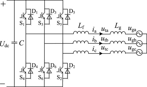
FIGURE 2. Topology of the grid-connected inverter.
From Figure 2, the mathematical model is shown in Eq. 1
The inverter generally adopts the vector control strategy based on grid voltage orientation, as shown in Figure 3. The power outer loop control generates d axis and q axis current command values respectively according to the demand of active and reactive power, and regulates the active and reactive power injected into the grid by adjusting the current values of d axis and q axis. In Figure 3, Pref and P are the reference and actual values of the active power respectively; Qref and Q are the reference value and actual value of reactive power respectively; idref and iqref are the reference values of d axis current and q axis current, respectively; id and iq are the d axis and q axis components of the inverter output current, respectively; Ud and Uq are the d axis and q axis components of the modulated voltage output by the current controller.
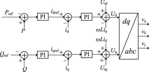
FIGURE 3. The vector control based on grid voltage orientation of the inverter.
3.2 Virtual inertia based secondary control method of DGs
In the DG grid connection inverter, the phase-locked loop (PLL) is needed to generate the reference phase of the power grid. The PLL usually uses the q-axis component generated by coordinate transformation and obtains the reference phase by controlling the q-axis voltage to zero (Nabil et al., 2022). The PLL adopted in the grid-connected inverter is given in Figure 4 where Utq is the q-axis component of the voltage vector at the grid-connection point. The working principle is that the instantaneous value of grid voltage is transformed to generate Utq. Through the PI controller and coefficient KV, the angular frequency difference Δω can be obtained. Then the angular frequency ωtra is obtained by adding Δω to the rated angular frequency ω0, and the measured value angle θtra of the phase is obtained by the integration process.
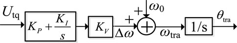
FIGURE 4. The PLL control strategy.
According to Figure 4, the power grid frequency f obtained from the PLL is given as
where KP and KI are the proportional and integral coefficients; KV is the gain coefficient. By taking the derivative of Eq. 2, the frequency change rate df/dt of the power grid is obtained as
Then the active power increment ΔPinertia is further obtained as
where Hinertia is the virtual inertia time constant. Therefore, the virtual inertia control of DGs based on the PLL control of the grid-side inverter is realized.
The above virtual inertia based secondary control method for DGs actively participating in power grid frequency regulation is shown in Figure 5.
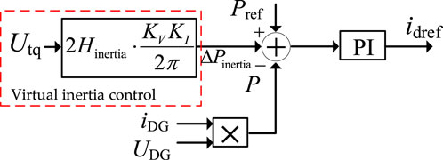
FIGURE 5. The virtual inertia based secondary control method for DGs.
4 Hierarchical control strategy for DGs considering communication delay
4.1 Small signal modeling of DGs with the hierarchical control strategy considering communication delay
The system small-signal model of hierarchical control scheme is firstly established in this part. The mathematical model of the grid-connected inverter in the synchronous rotating d-q reference frame is given as
From the primary PQ control in Section 3.1, the inverter current id and iq are controlled to follow the current references idref and iqref through the PI controller, and it yields
where KPId and KIId, KPIq and KIIq are the proportional and integral parameters of the PI controllers. The outer power loop controls are also based on the PI controllers which has
where KPP and KIP, KPQ and KIQ are the proportional and integral parameters of the power loop PI controllers. Then the following differential and algebraic equations can be obtained as
and
where xP, xQ, xid and xiq are the intermediate state variables. Based on the above derivation, the small signal model of the grid-connected inverter with primary PQ control is formulated as
where
Besides the primary PQ control, the virtual inertia based secondary control method of DGs is carried out for the fast frequency enhancement. Once receiving the measurements sent from the inverters, the secondary controller generates the supplementary power signal for frequency regulation. According to (4), the power reference command with the virtual inertia based secondary control is given as
where Pn is the power reference command from primary PQ control. Defining the control input as
Then the Small signal modeling of DGs with the hierarchical control strategy is
where the control input u = usec, and the matrix B is given as
However, the unavoidable time delay in signal sampling, measurement and execution may reduce the fast control performance of the virtual inertia based secondary control. The control structure diagram and tested time delay of some practical DGs integration system can be seen in Figure 6, which shows that the total time delay in the signal communication can be up to tens to hundreds of milliseconds. That is to say, the problems caused by the time delay may make the virtual inertia based secondary controller not only unable to achieve the expected control objectives, but also may lead to the deterioration or even instability of the dynamic performance of the inverter systems.
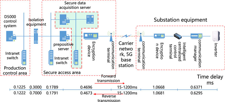
FIGURE 6. The control structure diagram and tested time delay of some practical DGs integration system.
Considering the time delay, the system model can be written as
The equivalent delays τ1 and τ2 contain both transmission delays of state variables and control inputs and satisfy
where τmax is a positive constant. It can be seen from Eq. 13 that the system stability under the control input u can be guaranteed with the small disturbance analysis method. However, the existing of delays τ1 and τ2 in Eq. 14 may destroy the system stability and make the stability condition no longer satisfied. Therefore, the effects of time delays in system state transmission and control inputs are simultaneously considered in the model and corresponding improved control is proposed in the next section.
4.2 Improved hierarchical control strategy based on virtual inertial considering communication delay
In this section, an improved hierarchical control strategy considering communication delay is designed based on the robust passivity method to compensate the equivalent delay disturbance. The main problem to design the improved control is how to deal with the time delay term both in state variable and control input properly. To handle this, the system dynamic equation is transformed in the following form.
where the equivalent delay disturbance is defined as
Since the equivalent delay time τ1 and τ2 are time-varying, the high-order polynomial with respect to time t can be used to express the equivalent delay disturbance D(t), which is given as
where ai (i = 0,…) is the constant coefficient of the polynomial. Considering that the noise becomes serious and the structure becomes complicated in the controller design, the high order dynamic behavior of the delay disturbance is ignored and it has
Then the robust passivity method to compensate the equivalent delay disturbance is proposed in this paper. For the system dynamic model (15), take the following variable transformation
where
where
If the actual control law
where
Then the system Lyapunov function with equivalent time delay is chosen as
where Qx and QD are the positive coefficient matrix. Together with Eq. 23, the derivative of the Lyapunov function
From Eq. 18 it is seen that the equivalent delay disturbance is assumed to be first-order. Thus it yields
If the adaptive law is designed as
then the derivative of the Lyapunov function
To ensure the system Lyapunov function
5 Case study
To verify the validation of the proposed control strategy, the DG integration system shown in Figure 7 is established in PSCAD platform. The capacity of each DG unit in the simulation model is 40 kW and use the hierarchical scheme based on virtual inertia control strategy proposed in this paper. The rated ac frequency is 50 Hz and the ac voltage is 380 V. Two cases including the load power fluctuation and the single-phase ground fault are conducted in this section to verify the validation of the proposed control strategy under common disturbances.
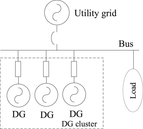
FIGURE 7. Simulation System topology of DGs.
5.1 Case 1
In this case, the initial active load in the system is 40 kW. At time 3 s, the load power increases to 60 kW. Besides, there exists time delay in the communication of the virtual inertia based secondary controller. The system simulation results with and without the proposed improved control are shown in Figures 8–10.

FIGURE 8. The simulation results with no time delay. (A) ac frequency, (B) ac voltage.
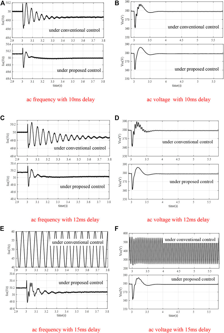
FIGURE 9. The simulation results with different time delays. (A) ac frequency with 10 ms delay, (B) ac voltage with 10 ms delay, (C) ac frequency with 12 ms delay, (D) ac voltage with 12 ms delay, (E) ac frequency with 15 ms delay, (F) ac voltage with 15 ms delay.
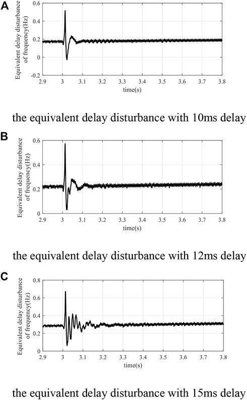
FIGURE 10. The simulation results of the equivalent delay disturbance of frequency. (A) the equivalent delay disturbance with 10 ms delay, (B) the equivalent delay disturbance with 12 ms delay, (C) the equivalent delay disturbance with 15 ms delay.
The system simulation results in Figures 8, 9 show the ac frequency and voltage response of the DG integration system during the load fluctuation in different situations. In Figure 8, the conventional virtual inertia control without any time delay compensation is adopted with no time delay in the signal communication. It can be seen that the system frequency and voltage can transition to a new steady state after the load increase at 3 s. However, when there exists time delay in the signal communication of the virtual inertia based secondary controller, the system response gets worse and even becomes unstable. From the system response under conventional control in Figure 9, it is seen that when the time delay is 10 ms, the system frequency is oscillating and the oscillation continues to 3.4 s. When the time delay increases to 12 ms, the dynamic response of system frequency and voltage gets larger oscillation with the conventional virtual inertia control. More serious is that the system loses stability when the time delay is 15 ms from Figures 9E, F with the conventional virtual inertial control. The simulation results under proposed robust passivity control method in Figure 9 show the ac frequency and voltage with different time delays to compensate the equivalent delay disturbance. It is seen that the ac frequency and voltage all respond satisfactorily no matter how much the communication time delay is. Figure 10 gives the simulation results of the equivalent delay disturbance of frequency, which indicates that the proposed control can track the equivalent disturbance caused by time delay and then compensate for the delay.
5.2 Case 2
In this case, the active load in the system is still 40 kW. At time 3 s, a single-phase ground fault occurs and lasts for 10 ms. It is also assumed that there exists different time delay in the communication of the virtual inertia based secondary controller. The system simulation results with and without the proposed control are shown in Figure 11. Besides, the system performance is also compared with the time delay compensation control in the existing literature (Natoriand and Ohnishi, 2008).
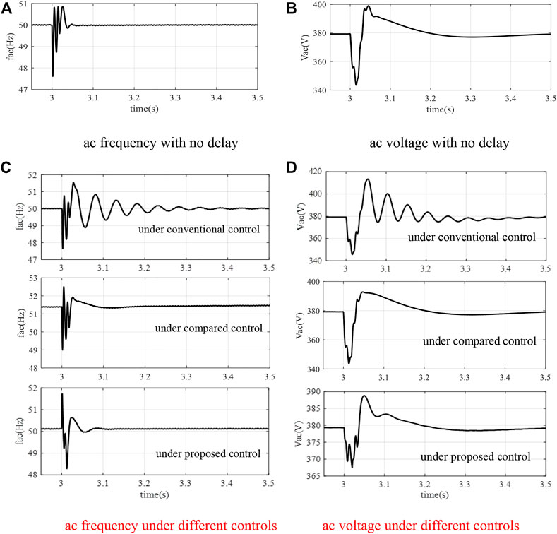
FIGURE 11. The simulation results with 10 ms delay of case 2. (A) ac frequency with no delay, (B) ac voltage with no delay, (C) ac frequency under different controls, (D) ac voltage under different controls.
The simulation results show that during the single-phase ground fault, the transient process is deteriorated when there exist time delays in the signal communication with the conventional virtual inertia control. However, when the proposed robust passivity method works to compensate the equivalent delay disturbance, the oscillations of ac frequency and voltage can still be decreased and the impact of time delay can be well suppressed. The system response is also compared with the time delay compensation control in (Natoriand and Ohnishi, 2008), which shows that although the oscillations can be suppressed, large overshoots still exist. It can be concluded from the above cases that even the system suffers large disturbances, the improved hierarchical control strategy based on the robust passivity method can significantly enhance the robustness of the DG integration system for superior dynamic response when there exists time delay in the communication channel.
6 Conclusion
As the rapid development of DGs and the development of virtual inertia control, the inherent communication delay problems around the control link makes an impact on the fast support effect which cannot be ignored. This paper proposes the virtual inertia based hierarchical control scheme for DGs considering communication delay, which includes the PQ primary control and the virtual inertia based secondary control method. To enhance the inertia support ability of the DG integration system, an improved hierarchical control strategy considering communication delay is designed based on the robust passivity method to compensate the equivalent delay disturbance. The effectiveness verification of the proposed control is then carried out with the simulation cases in PSCAD platform. In further research, it is necessary to conduct the inertia enhancement method study of multiply distribution systems with DGs on a broader level to comprehensively improve the stability of the distribution power system.
Data availability statement
The raw data supporting the conclusion of this article will be made available by the authors, without undue reservation.
Author contributions
CZ: Conceptualization, methodology, validation, writing–original draft. YL: Data curation, writing–original draft. KZ: Methodology, conceptualization, writing–review and editing. XX: Methodology, validation. JL: Writing–review and editing.
Funding
This work was supported by National Key Research and Development Program of China (2021YFB2501602).
Conflict of interest
Author YL was employed by State Grid Nanjing Power Supply Company.
The remaining authors declare that the research was conducted in the absence of any commercial or financial relationships that could be construed as a potential conflict of interest.
Publisher’s note
All claims expressed in this article are solely those of the authors and do not necessarily represent those of their affiliated organizations, or those of the publisher, the editors and the reviewers. Any product that may be evaluated in this article, or claim that may be made by its manufacturer, is not guaranteed or endorsed by the publisher.
References
Beck, H. P., and Hesse, R. (2007). Virtual synchronous machine[C]//2007 9th international conference on electrical power quality and utilization(EPQU). Spain: IEEE, 1–6.
Guan, M. Y. (2022). Scheduled power control and autonomous energy control of grid-connected energy storage system (ESS) with virtual synchronous generator and primary frequency regulation capabilities. IEEE Trans. Power Syst. 37 (2), 942–954. doi:10.1109/tpwrs.2021.3105940
Guo, M. L., Zheng, J. Y., Mei, F., Sha, H., Gao, A., and Xie, Y. (2023). Double-layer AGC frequency regulation control method considering operating economic cost and energy storage SOC consistency. Int. J. Electr. Power and Energy Syst. 145, 108704. doi:10.1016/j.ijepes.2022.108704
Guo, X., Zhu, D., and Hu, J. (2022). Inertial PLL of grid-connected converter for fast frequency support[J]. CSEE J. Power Energy Syst. early access.
Haldar, A., Khatua, R., and Malkhandi, A. (2022). Delay based virtual inertia emulation for a grid forming system[C]//2022 IEEE Power and Energy Conference at Illinois (PECI). IL, USA: Champaign, 10–11.
Kheshti, M., Lin, S., Zhao, X., Ding, L., Yin, M., and Terzija, V. (2022). Gaussian distribution-based inertial control of wind turbine generators for fast frequency response in low inertia systems. IEEE Trans. Sustain. Energy 13 (3), 1641–1653. doi:10.1109/tste.2022.3168778
Lian, Z., Deng, C., Wen, C., Guo, F., Lin, P., and Jiang, W. (2021). Distributed event-triggered control for frequency restoration and active power allocation in microgrids with varying communication time delays. IEEE Trans. Industrial Electron. 68 (9), 8367–8378. doi:10.1109/tie.2020.3016272
Liu, S. C., Wang, X. Y., and Liu, P. X. (2015). Impact of communication delays on secondary frequency control in an islanded microgrid. IEEE Trans. Industrial Electron. 62 (4), 2021–2031. doi:10.1109/tie.2014.2367456
Liu, Z. W., Miao, S. H., Fan, Z. H., Liu, J., and Tu, Q. (2019). Improved power flow control strategy of the hybrid AC/DC microgrid based on VSM. Transm. Distribution 13 (1), 81–91. doi:10.1049/iet-gtd.2018.5839
Meng, X., Liu, J., and Liu, Z. (2019). A generalized droop control for grid-supporting inverter based on comparison between traditional droop control and virtual synchronous generator control. IEEE Trans. Power Electron. 34 (6), 5416–5438. doi:10.1109/tpel.2018.2868722
Nabil, M., Zhou, W., and Behrooz, B. (2022). Comparison of PLL-based and PLL-less control strategies for grid-following inverters considering time and frequency domain analysis. IEEE Access 10, 80518–80538. doi:10.1109/access.2022.3195494
Nan, C., Tingcun, W., Ke, S., and Wang, R. (2018). Digital controller based on delta operator for high-frequency DC–DC switching converters. IET Power Electron. 11 (7), 1224–1230. doi:10.1049/iet-pel.2017.0556
Natoriand, K., and Ohnishi, K. (2008). A design method of communication disturbance observer for time-delay compensation, taking the dynamic property of network disturbance into account. IEEE Trans. Industrial Electron. 55 (5), 2152–2168. doi:10.1109/tie.2008.918635
Quan, X., Yu, R., Zhao, X., Lei, Y., Chen, T., Li, C., et al. (2020). Photovoltaic synchronous generator: Architecture and control strategy for a grid-forming PV energy system. J]. IEEE J. Emerg. Sel. Top. Power Electron. 08 (2), 936–948. doi:10.1109/jestpe.2019.2953178
Razavi, S. E., Rahimi, E., Javadi, M. S., Nezhad, A. E., Lotfi, M., Shafie-khah, M., et al. (2019). Impact of distributed generation on protection and voltage regulation of distribution systems: A review. Renew. Sustain. Energy Rev. 105, 157–167. doi:10.1016/j.rser.2019.01.050
Sun, D., Liu, H., Gao, S., Wu, L., Song, P., and Wang, X. (2020). Comparison of different virtual inertia control methods for inverter-based generators. J. Mod. Power Syst. Clean Energy 8 (4), 768–777. doi:10.35833/mpce.2019.000330
Suud, A. H., Şahin, S., and Saffet, A. (2022). Impact of virtual inertia on stability delay margins of micro grids with communication time delay[C]//2022 4th Global Power, Energy and Communication Conference (GPECOM). Turkey: Nevsehir, 14–17.
Vafamand, N., Khooban, M. H., Dragičević, T., Boudjadar, J., and Asemani, M. H. (2019). Time-delayed stabilizing secondary load frequency control of shipboard microgrids. IEEE Syst. J. 13 (3), 3233–3241. doi:10.1109/jsyst.2019.2892528
Xiong, L., Liu, L., Liu, X., and Liu, Y. (2021). Frequency trajectory planning based strategy for improving frequency stability of droop-controlled inverter based standalone power systems. IEEE J. Emerg. Sel. Top. Circuits Syst. 11 (1), 176–187. doi:10.1109/jetcas.2021.3052006
Yang, D., Yan, G., Zheng, T., Zhang, X., and Hua, L. (2022). Fast frequency response of a DFIG based on variable power point tracking control. IEEE Trans. Industry Appl. 58 (4), 5127–5135. doi:10.1109/tia.2022.3177590
Yang, H. X., Fang, J. Y., and Tang, Y. (2019). Exploration of time-delay effect on the stability of grid-connected power converters with virtual inertia[C]//2019 10th International Conference on Power Electronics and ECCE Asia (ICPE 2019 - ECCE Asia). Busan, Korea (South), 27–30.
Yang, H. X., Fang, J. Y., and Yi, T. (2019). On the stability of virtual inertia control implemented by grid-connected power converters with delay effects [C]//2019 IEEE Energy Conversion Congress and Exposition (ECCE). MD, USA: Baltimore.
Yuan, Z-L., Zhang, C-K., Shangguan, X-C., Jin, L., Xu, D., and He, Y. (2022). Stability analysis of load frequency control for shipboard microgrids with occasional large delays. IEEE Trans. Circuits Syst. II Express Briefs 69 (4), 2161–2165. doi:10.1109/tcsii.2021.3135962
Zhang, H., Xiang, W., Lin, W., and Wen, J. (2021). Grid forming converters in renewable energy sources dominated power grid: Control strategy, stability, application, and challenges. J. Mod. Power Syst. Clean Energy 09 (6), 1239–1256. doi:10.35833/mpce.2021.000257
Keywords: distributed generations, hierarchical scheme, virtual inertia, frequency support, communication delay
Citation: Zhou C, Liao Y, Zhang K, Xu X and Liao J (2023) Virtual inertia based hierarchical control scheme for distributed generations considering communication delay. Front. Energy Res. 11:1135038. doi: 10.3389/fenrg.2023.1135038
Received: 31 December 2022; Accepted: 15 February 2023;
Published: 01 March 2023.
Edited by:
Xue Lyu, Pacific Northwest National Laboratory (DOE), United StatesReviewed by:
Dejian Yang, Northeast Electric Power University, ChinaLi He, The University of Texas at Dallas, United States
Copyright © 2023 Zhou, Liao, Zhang, Xu and Liao. This is an open-access article distributed under the terms of the Creative Commons Attribution License (CC BY). The use, distribution or reproduction in other forums is permitted, provided the original author(s) and the copyright owner(s) are credited and that the original publication in this journal is cited, in accordance with accepted academic practice. No use, distribution or reproduction is permitted which does not comply with these terms.
*Correspondence: Kaifeng Zhang, a2FpZmVuZ3poYW5nQHNldS5lZHUuY24=