 Wei Zhou
 Yonghui Sun
 Xuanjun Zong2
94% of researchers rate our articles as excellent or good
Learn more about the work of our research integrity team to safeguard the quality of each article we publish.
Find out more
ORIGINAL RESEARCH article
Front. Energy Res., 09 March 2023
Sec. Smart Grids
Volume 11 - 2023 | https://doi.org/10.3389/fenrg.2023.1134221
This article is part of the Research TopicHydrogen Technologies Integrated into Smart GridsView all 5 articles
Under the theme of low carbon, in order to improve the economy of integrated energy system (IES), optimize the operational flexibility of equipment and further reduce the carbon emission level of IES, a low-carbon economy operation strategy of the IES is proposed. First, the IES is considered to participate in the carbon trading market, and the carbon trading mechanism is introduced to control the carbon emissions of the system. Second, on the basis of the working characteristics of liquid air energy storage (LAES), organic Rankine cycle (ORC), and combined heat and power (CHP), the LAES-ORC-CHP system is established in the IES to achieve flexible supply of heat and power. Then, aiming at minimizing the sum of system operation costs and carbon transaction costs, the low-carbon economy optimal dispatch model of IES is proposed. Finally, the effectiveness of the proposed model is verified by setting multiple operation scenarios. Simulation results show that the proposed model can fully consider and balance the economy and low carbon level of the system and provide a reference for the low-carbon economic dispatch operation of the IES.
All countries in the world are in consensus to promote the close coupling of multi-energy systems, reduce the consumption of fossil fuels, and improve the access ratio of clean energy (Kong et al., 2016; Alabi et al., 2022a). Multi-energy complementation, integration, and optimization have become an important breakthrough in global energy revolution and the direction of future energy development and transformation (Wu et al., 2016). The integrated energy system characterized by the coordinated and efficient utilization of conventional energy and new energy is an important part (Lin and Bie, 2016; Kang et al., 2022; Shen et al., 2022). The IES is widely used because it is internally coupled with a variety of energy conversion equipment, which can realize the complementary advantages between different energy sources (Gao et al., 2022). In order to achieve the goal of low carbon, the optimization research of the IES has also begun to transform from traditional economic dispatch to low-carbon economic dispatch (Wang et al., 2022a; Liu et al., 2022; Lyu et al., 2023; Xu et al., 2023).
The carbon trading mechanism is considered an effective means to reduce carbon emissions in energy systems (Lu et al., 2023a; Lu et al., 2023b). After years of development, the global carbon trading market has grown gradually with a huge development potential. It is a mechanism that uses carbon emissions as a commodity for circulation and trading in the market and uses market means to control regional carbon emissions (Alabi et al., 2022b; Wang et al., 2022b). Cheng et al. (2020) studied the low-carbon operation of multiple energy systems by coordinating the transmission and distribution layer through the comprehensive price of energy carbon, and a carbon emission flow model was used to uniformly price carbon emissions of different energy systems according to the actual emission contribution of consumers. In Guo et al. (2022), the carbon trading costs were calculated on the basis of the carbon emission range, and a low-carbon operation model of the IES was proposed with the goal of minimizing the sum of power generation cost and carbon dioxide trading cost. In Li et al. (2022), the carbon trading mechanism was introduced into the IES and a new low-carbon scheduling method was proposed, which has had good economic and low-carbon environmental benefits. Guo and Xu (2022) elaborated the relationship between carbon emissions and carbon trading prices in the carbon trading mechanism and analyzed the mechanism of demand–response participating in low-carbon economic dispatch of the IES. Simulation results have shown that the proposed method is effective in reducing carbon emissions and operating costs. Xiang et al. (2021) established a low-carbon scheduling model for the integrated power and natural gas energy system under the carbon trading mechanism and proposed a fast solution strategy considering the granularity of the time period, which could effectively reduce carbon emissions and improve the convergence speed. In Chen et al. (2022), a multi–micro energy grid–distributed optimal scheduling method considering the demand side of the carbon trading mechanism was proposed, and the hierarchical distributed solution was carried out on the basis of the goal cascade technology. While protecting the information privacy of each micro energy grid, the low-carbon economic operation of the multi–micro energy grid–integrated energy system is realized. In Wang et al. (2022c), the carbon emission coefficient and ladder-type carbon trading mechanism were used to calculate the carbon trading costs, and the economic benefits of carbon capture power plants were evaluated. The simulation results showed that carbon emissions of the proposed model were greatly reduced but the total costs were slightly increased. In Yang et al. (2023), an operation strategy of carbon capture devices was proposed on the basis of stepped carbon punishment response to solve the conflict between carbon capture and profitability caused by the establishment of the carbon market, which was applied to the improved IES. The low-carbon nature of the IES is mainly improved through external means such as the carbon trading mechanism in the abovementioned low-carbon economic dispatch research. However, in the existing results, the potential flexible resources based on low-carbon equipment are rarely considered in IES.
Liquid air energy storage is a renewable energy technology to achieve energy conservation and emission reduction. When compared with other energy storage technologies, LAES can not only effectively store intermittent renewable energy but also have the advantages of no geographical restrictions, low investment costs, and large energy storage densities (Ding et al., 2022). When used in combination with clean energy (such as wind energy and light energy), the LAES system can be completely green, which not only saves the cost of the entire energy storage system but also protects the ecological environment (Da et al., 2022). In Fan et al. (2023), a coupling system combining the thermal power plant and LAES was proposed, and technical and economic analyses were carried out to obtain the optimal configuration of the integrated system and verify its economic benefits. Liu et al. (2023) studied the performance of independent LAES systems with different compression and expansion stages and used the particle swarm optimization (PSO) algorithm to optimize all cases. In Mousavi et al. (2022), a subcritical LAES system was designed and a comprehensive study on energy, environment, economy, and consumption economy was carried out; this design aimed to minimize the number of LAES equipment to reduce its structural complexity, increase its application, and improve its performance. In Kim et al. (2022), the thermal energy storage unit in LAES was parameterized, which improved the effectiveness of the thermal energy storage unit. On the basis of the benchmark LAES (BLAES) system, Li and Duan (2022) designed a new solar-assisted LAES system and introduced an organic Rankine cycle device to improve the round-trip efficiency of the entire system. The abovementioned references have studied the energy storage characteristics of LAES but few have introduced it into the IES to explore its low-carbon characteristics.
Liquid air energy storage can store electric energy through liquefying air, which is not limited by terrain. At the same time, the system efficiency is improved due to the recovery of compressed heat. However, due to the fact that the air cannot be completely liquefied, about 15%–45% of the compression heat generated by LAES in the compressed air link cannot be used in the discharge link. In order to make full use of this part of waste heat, an LAES-ORC system is established by coupling ORC in LAES. At the same time, the constant thermoelectric ratio output of the gas turbine (GT) can often not achieve the optimal energy supply ratio of the thermal and electrical loads, while the ORC can cooperate with the GT and waste heat boiler (WHB) to form CHP with flexible thermal and electrical outputs. Therefore, the LAES-ORC-CHP system is proposed in this study to realize the flexible supply of thermoelectric power in the IES.
Based on the abovementioned discussions, the impact of the carbon trading market and LAES, ORC, and CHP cooperative operation strategy on the operating cost and carbon emissions of the IES are comprehensively studied to propose an IES optimization scheduling model, considering the ladder-type carbon trading mechanism and LAES-ORC-CHP system. First, a ladder-type carbon trading mechanism is introduced and the market means is developed to control the carbon emissions of the IES. Then, the input and output characteristics of LAES, ORC, and CHP are analyzed, and a LAES-ORC-CHP system is proposed to realize the flexible supply of heat and electricity and then play a role in low-carbon economy by cooperating with the carbon trading mechanism from the supply side of the IES. Finally, the effectiveness and rationality of the proposed model are verified by setting up multiple scenes for comparison.
The IES studied in this article is a multi-input and multi-output system, which is internally coupled with multiple types of energy conversion and storage equipment and can meet various load requirements (Xiong et al., 2022). The specific structure of the IES is shown in Figure 1. The energy input terminals include natural gas, power purchase, wind power, and photovoltaic (PV). Energy conversion equipment include the gas turbine, gas boiler (GB), waste heat boiler, electric boiler (EB), absorption chiller (AC), electric chiller (EC), and organic Rankine cycle (ORC). The GT and WHB constitute the combined heat and power. The energy storage equipment include LAES, heat storage tank, gas storage tank, and cold storage tank. The energy output terminals include electrical load, thermal load, gas load, and cooling load.
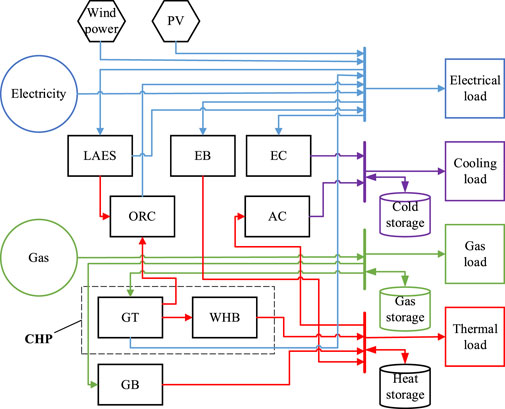
FIGURE 1. Internal structure diagram of IES.
The carbon trading mechanism aims to control carbon emissions by establishing legal carbon emission rights and allowing producers to trade carbon emission rights in the market. The carbon emission right quota for each carbon emission source is allocated by the regulatory authority, and the reasonable production and emission based on its own quota are conducted by the manufacturer. If the actual carbon emission is lower than the allocated quota, the remaining quota is involved in the carbon trading market for trading. Otherwise, the carbon emission right quota has to be purchased. The ladder-type carbon trading mechanism model mainly includes the carbon emission right quota model, actual carbon emission model, and the ladder-type carbon trading cost calculation model.
There are three types of carbon emission sources in the IES that include electricity purchasing, GB, and GT. At the same time, it is assumed that electricity purchasing is from coal-fired units. The time period covered by the carbon emission right quota for each carbon emission source is daily. The carbon emission quota for the whole day is calculated. The regulatory authority will notify the allocated quota 1 day in advance. It is not necessary to predict the allocated quota, and the corresponding carbon emission right quota will be calculated according to the output of the equipment on the day ahead of dispatch. It follows from Chen et al. (2021) that the carbon emission right quota model is given by
where
The actual carbon emission model in this study has been established according to Lu et al. (2023a) and Chen et al. (2021). According to them, the calculation of carbon emission adopts a quadratic function.
where
Therefore, the carbon emissions of the IES participating in carbon trading are calculated as follows:
where
The traditional carbon trading mechanism model is given by
where
Based on the allocated free carbon emissions, the number of emission intervals is specified; the higher the emission interval, the higher is the carbon trading price. The ladder-type carbon trading cost calculation model is given by
where
LAES is mainly composed of three stages: the charging stage, storage stage, and discharge stage. First, the energy of surplus wind power and photovoltaic is used by LAES to compress the air through multi-stage compressors, and the waste heat in the compression process is recovered to improve the subsequent expansion capability. Second, air enters the liquefaction subsystem, where it is liquefied and stored. Third, the liquid air changes into high-pressure air after passing through the gasification unit, and then expands and works through the multi-stage expander to release the stored electric energy. At the same time, the residual cooling in the expansion process is recovered to reduce the temperature of compressed air for the subsequent throttling liquefaction process. Because the compressed heat generated in the air liquefaction stage cannot be fully utilized in the discharge stage, the remaining compressed heat is input into the ORC for waste heat power generation. In addition, the CHP unit can also supply excess waste heat to the ORC for power generation. In order to show the internal structure and input–output relationship of the LAES-ORC-CHP system more clearly and concretely and to facilitate the next case study, the workflow of the LAES-ORC-CHP system is shown in Figure 2.
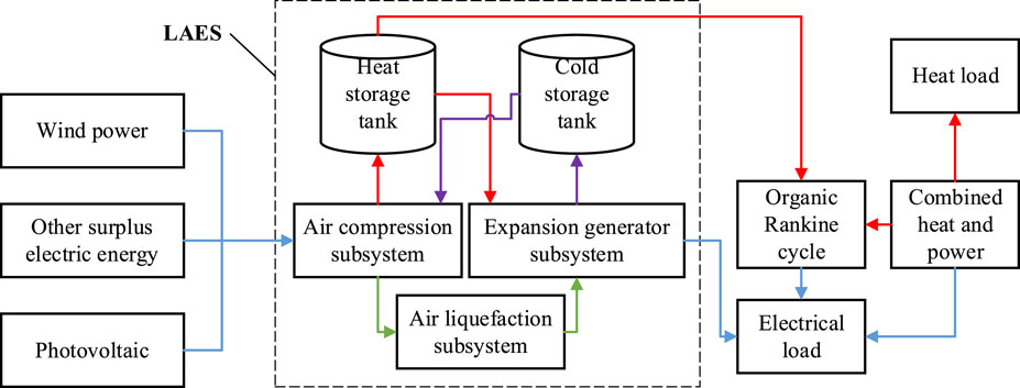
FIGURE 2. Workflow diagram of LAES-ORC-CHP system.
The liquefied air storage system model is given by
where
The CHP model is given by
where
The ORC model is given by
where
The output power of the LAES-ORC-CHP system is given by
where
The objective function includes system operation cost and carbon trading cost. At the same time, the system operation cost consists of energy purchase cost and equipment maintenance cost, which is given by
where
1) System operation cost
where
(2) Carbon trading cost
For details of the carbon trading cost, please see Eq. 4 when the traditional carbon trading mechanism is utilized and Eq. 5 when the ladder-type carbon trading mechanism is utilized.
1) Gas boiler
where
2) Electric boiler
where
3) Absorption chiller
where
4) Electric chiller
where
5) LAES-ORC-CHP system
For details on the LAES-ORC-CHP system, please refer Eqs 6–9.
6) Renewable energy
where
7) Energy storage equipment
The energy storage equipment model is established according to Chen et al. (2021) and Li et al. (2019).
In order to maintain the energy balance of the energy storage system, ensure normal operation of the energy storage system cycle and reduce the impact on the service life of the energy storage equipment; the stored energy at the end of the dispatch period is set to be the same as the stored energy at the beginning (Li et al., 2019).
where
8) Energy purchasing
where
9) Energy balance
where
In this study, the LAES-ORC-CHP system is proposed, which can not only effectively store renewable energy and other surplus electric energy but also flexibly supply electricity and heat according to the electrothermal load change. Since the energy that inputs to the LAES-ORC-CHP system mainly includes renewable energy and natural gas which are more low carbon and environmentally friendly, it can be optimized in coordination with the carbon trading mechanism to achieve low-carbon economic dispatch of the IES. The relationship of modeling and solution is shown in Figure 3.

FIGURE 3. Relationship of modeling and solving.
The proposed low-carbon economic optimal dispatch model of the IES in this article is non-linear. The non-linear part mainly includes Eqs 2 and 5. In the Gurobi solver, the quadratic function can be directly processed by calling the addConstr( ) and addConstrs( ) functions, and the piecewise function can be processed by calling the addGenConstrPWL( ) function.
In this article, the typical IES in North Jiangsu which contains electricity, heat, gas, and cold is selected as the simulation object to verify the effectiveness of the proposed optimization model. The optimal dispatch is carried out during a period of 24 h. The prediction curves of various loads and wind power and photovoltaic output in the IES are shown in Figure 4. Time-sharing electricity price is adopted, as shown in Figure 5. The parameters of each energy conversion equipment in the IES are shown in Table 1. The parameters of LAES are shown in Table 2. According to Wang (2019) and Ma (2021), when the compression stage is determined, the expansion unit will do the most work when the stage is equal to the compression stage. According to the analysis of the calculation results of the compressor units and expansion units of different stages, the four-stage compressor unit and the four-stage expansion unit are more suitable for the LAES system and ensure a higher cycle efficiency of the system. The carbon emission calculation coefficient values are shown in Table 3.
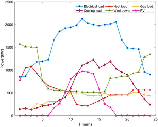
FIGURE 4. Prediction curve of wind power, photovoltaic, and multi-load in IES.
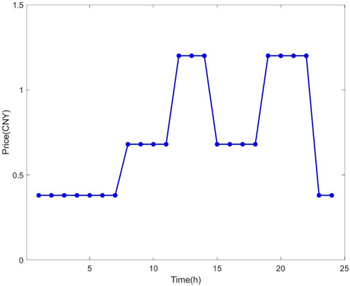
FIGURE 5. Time-sharing electricity price.
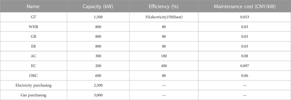
TABLE 1. Parameters of equipment.
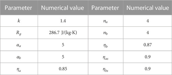
TABLE 2. Parameter information of LAES.
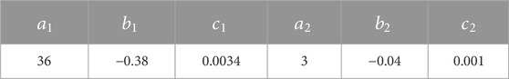
TABLE 3. Calculation coefficients of carbon emission.
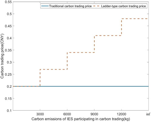
FIGURE 6. Traditional carbon trading price and ladder-type carbon trading price.
The following five scenarios are set for comparison and analysis:
• Scenario 1: under the ladder-type carbon trading mechanism, the carbon trading costs are not considered in the optimization goal.
• Scenario 2: under the traditional carbon trading mechanism, the carbon trading costs are considered in the optimization goal.
• Scenario 3: under the ladder-type carbon trading mechanism, the carbon trading costs are considered in the optimization goal.
• Scenario 4: on the basis of scenario 3, the LAES system is considered.
• Scenario 5: on the basis of scenario 3, the LAES-ORC-CHP system is considered.
The economy and carbon emission of the IES in the five scenarios are shown in Table 4.
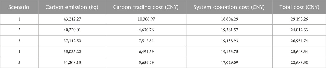
TABLE 4. Optimal dispatch results of IES in different scenarios.
Scenarios 1, 2, and 3 are used to compare and analyze the effectiveness of considering the carbon trading mechanism in the IES.
It can be seen from Table 4 that compared with scenarios 2 and 3, the objective function of scenario 1 without considering carbon trading cost results in the highest carbon emission of scenario 1. Although the system operation cost of scenario 1 is the lowest, its total cost is the highest because of its very high carbon trading cost. The traditional carbon trading mechanism is considered in scenario 2. When compared with scenario 1, its carbon emissions are decreased by 2,992.26 kg or 6.92%. When compared with scenario 1, the system operation costs of scenario 2 are increased by 577.28 CNY or 2.98%, but the total costs are decreased by 17.75%. It is shown that the traditional carbon trading mechanism can limit the carbon emissions of the IES to a certain extent, while considering the economy of the system.
The ladder-type carbon trading mechanism is considered in scenario 3. When compared with scenarios 1 and 2, the carbon emissions in scenario 3 are decreased by 14.12% and 7.73%, respectively. It is shown that when compared with the traditional carbon trading mechanism, the ladder-type carbon trading mechanism is stricter in limiting the carbon emissions of the IES, which is more conducive for the realization of the low-carbon goal of the IES. The total costs of scenario 3 are increased by 2,939.41 CNY when compared with those of scenario 2, but they are decreased by 2,241.52 CNY when compared with those of scenario 1. Because the ladder-type price is used in the ladder-type carbon trading mechanism, the higher the carbon trading price is, corresponding to the range with larger carbon emissions, the carbon trading costs in scenario 3 are higher than those in scenario 2. This is the main reason why the total costs of scenario 3 are higher than those of scenario 2.
Scenarios 3, 4, and 5 are set to compare and analyze the effectiveness of considering the LAES-ORC-CHP system in the IES.
It can be seen from Table 4 that the ladder-type carbon trading mechanism and the LAES system are considered in scenario 4, while the ORC is not considered. In terms of carbon emission, the carbon emissions of scenario 4 are decreased by 2,077.28 kg or 5.60%, when compared with those of scenario 3. In terms of economy, when compared with those of scenario 3, the carbon trading costs in scenario 4 are decreased by 1,018.22 CNY, the system operation costs are decreased by 285.18 CNY, and the total costs are decreased by 1,303.40 CNY. It is shown that adding the LAES system to the IES is beneficial in improving the economy and low carbon of the system.
The ladder-type carbon trading mechanism and the LAES-ORC-CHP system are considered in scenario 5, which is the proposed dispatch model in this work. Compared with those of scenarios 3 and 4, the carbon emissions of scenario 5 are decreased by 5,904.37 kg and 3,827.09 kg, respectively. The carbon trading costs in scenario 5 are 1,853.52 CNY lower than those of scenario 3 and 835.30 CNY lower than those of scenario 4. When compared with those of scenarios 3 and 4, the system operation costs of scenario 5 are reduced by 2,409.84 CNY and 2,124.66 CNY, respectively. The total costs of scenario 5 are 4,263.36 CNY lower than those of scenario 3 and 2,959.96 CNY lower than those of scenario 4, respectively. Combining LAES with ORC and CHP to develop the LAES-ORC-CHP system can further reduce the economic costs of the IES when compared with a single LAES, and further reduce the carbon emissions of the IES in coordination with the carbon trading mechanism.
The flow directions of heat generated by GT are shown in Figure 7. The sources of heat used by the ORC to generate electricity are shown in Figure 8. The input and output of the LAES-ORC-CHP system are shown in Figure 9. Figures 7–9 are presented to analyze the energy flow inside the LAES-ORC-CHP system.

FIGURE 7. Flow direction of thermal power generated by GT.

FIGURE 8. Heat source input into ORC.
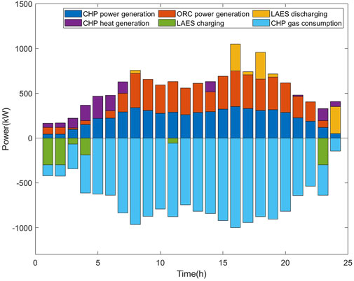
FIGURE 9. Input and output of LAES-ORC-CHP system.
CHP is composed of the GT and WHB. It can be seen from Figure 7 that a part of the heat generated by the GT flows into the ORC and a part into the WHB. At night, due to high heat load and low electrical load, most of the heat generated by the GT flows to the WHB for heating and during the daytime, due to the high electrical load and low heat load, most of the heat generated by the GT flows to the ORC for power generation.
It can be seen from Figure 8 that the heat input into the ORC is mainly from LAES and CHP, and the proportion of CHP is higher. This is because most of the heat in LAES is used for its own discharge phase, and only a small part of heat is input into the ORC, while the heat generated by CHP is fully be input into the ORC. Figure 9 shows that the LAES-ORC-CHP system can store electric energy during the period of abundant wind power, and photovoltaic resources can supply heat during the period with high heat load, while supplying electricity in the period with high electrical load. Simultaneously, the electric energy generated by CHP and the ORC are the main sources of output electric energy in the LAES-ORC-CHP system. LAES can increase the consumption rate of renewable energy and further improve the economy and low carbon of the IES operation.
According to the abovementioned analysis, the LAES-ORC-CHP system mainly outputs two kinds of energy, namely, electric energy and thermal energy. Figure 10 and Figure 11 reflect the balance of electric power and thermal power in scenario 5, respectively. From the perspective of power balance, the reasons why the LAES-ORC-CHP system can reduce system carbon emissions and improve economy in IES optimal dispatch are analyzed.
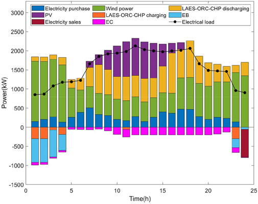
FIGURE 10. Electric power balance of scenario 5.
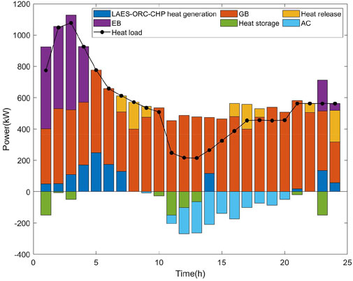
FIGURE 11. Heat power balance of scenario 5.
It can be seen from Figure 10 that during night time, the wind resources are abundant, and the LAES in the LAES-ORC-CHP system is in the charging state, which improves the consumption rate of wind power. During the period of high electricity price and load in the daytime, the LAES-ORC-CHP system releases a large amount of electric energy to meet user demands and reduce the purchased electricity of the IES. It follows from Figure 1 that the stored electricity in LAES comes from renewable energy, while CHP generates electricity by consuming natural gas. On one hand, in the period of high electricity price, it is cheaper to use natural gas to generate electricity than to purchase electricity, and renewable energy is not included in the cost here. Therefore, the high output state of the LAES-ORC-CHP system is conducive in reducing the economic cost. On the other hand, the carbon emission coefficient of natural gas is lower than that of coal power generation units, and wind power has no carbon emissions, so the LAES-ORC-CHP system is conducive in improving the low-carbon nature of IES.
It can be derived from Figure 11 that the proportion of heat generated by the LAES-ORC-CHP system in the heating system is not high because the heat generation efficiency of the GB and EB is much higher than that of CHP. The use of GB and EB for heat supply is more in line with the pursuit of economic goals of the IES. At the same time, when compared with the EB, the output power of the GB is greater. This is because although the heat production efficiency of EB is similar to that of GB, EB consumes electric energy, while GB consumes natural gas, and the carbon emission coefficient of natural gas is lower. Therefore, increasing the proportion of output power of the GB in the heating system is more consistent with the low-carbon goal of the IES.
In order to significantly reduce the carbon emissions of the IES and further achieve the goal of low-carbon economic operation of the system, an IES optimal dispatch strategy considering the ladder-type carbon trading mechanism and the LAES-ORC-CHP system have been proposed in this article. First, the carbon trading mechanism was introduced into the IES to control the carbon emissions of the system by market means. Second, the flexibility and low-carbon energy supply of some equipment in the IES were deeply explored. Based on the working characteristics of LAES, ORC, and CHP, the LAES-ORC-CHP system that can realize the flexible supply of heat and power was established. Then, the LAES-ORC-CHP system and ladder-type carbon trading mechanism were jointly optimized, and the IES low-carbon economy dispatch model was established with the goal of minimizing the total cost. Finally, the simulation analysis and verification showed that when compared with the IES optimization model without considering carbon trading mechanism and the LAES-ORC-CHP system, the carbon emissions of the model proposed in this article are reduced by 12,004.14 kg, the carbon trading cost reduced by 4,729.68 CNY, and the total cost reduced by 6,504.88 CNY, that effectively improved the economy and low carbon of the operation of the IES.
In this article, the optimal dispatch of the IES stays at the level of the steady state analysis, while the natural gas system and thermal system are different from the power system, which have the characteristics of management and storage. The existing unified time scale model cannot reflect the transient and time-delay characteristics of the IES in essence. Therefore, how to establish an optimization model of the IES considering the dynamic characteristics is worthy of further study.
The original contributions presented in the study are included in the article/Supplementary Material; further inquiries can be directed to the corresponding author.
All authors listed have made a substantial, direct, and intellectual contribution to the work and approved it for publication.
This work is supported by the National Natural Science Foundation of China (No. 62073121).
The authors would also like to acknowledge reviewers for their constructive comments and careful revision of this article.
Authors XZ, HZ, and SZ were employed by the company Economic Research Institute, State Grid Jiangsu Electric Power Co, Ltd.
The remaining authors declare that the research was conducted in the absence of any commercial or financial relationships that could be construed as a potential conflict of interest.
All claims expressed in this article are solely those of the authors and do not necessarily represent those of their affiliated organizations, or those of the publisher, editors, and reviewers. Any product that may be evaluated in this article, or claim that may be made by its manufacturer, is not guaranteed or endorsed by the publisher.
Alabi, T. M., Agbajor, F. D., Yang, Z., Lu, L., and Ogungbile, J. A. (2022). Strategic potential of multi-energy system towards carbon neutrality: A forward-looking overview. Chengdu: Energy and Built Environment. doi:10.1016/j.enbenv.2022.06.007
Alabi, T. M., Aghimien, E. I., Agbajor, F. D., Yang, Z., Lu, L., Adeoye, A. R., et al. (2022). A review on the integrated optimization techniques and machine learning approaches for modeling, prediction, and decision making on integrated energy systems. Renew. Energ 194, 822–849. doi:10.1016/j.renene.2022.05.123
Chen, J., Hu, Z., Chen, J., Chen, Y., Gao, M., and Lin, M. (2021). Optimal dispatch of integrated energy system considering ladder-type carbon trading and flexible double response of supply and demand. High. Volt. Eng. 47, 3094–3106. doi:10.13336/j.1003-6520.hve.20211094
Chen, J., Jia, Y., Han, X., Ren, H., and Ge, H. (2022). Distributed coordinated optimal scheduling of multi-micro integrated energy systems considering demand-side carbon trading mechanism. Power Syst. Technol., 1–10. doi:10.13335/j.1000-3673.pst.2022.1461
Cheng, Y., Zhang, N., Zhang, B., Kang, C., Xi, W., and Feng, M. (2020). Low-carbon operation of multiple energy systems based on energy-carbon integrated prices. IEEE Trans. Smart Grid 11, 1307–1318. doi:10.1109/tsg.2019.2935736
Da, L., Duan, L., and Ding, X. (2022). New regulation strategies study of solar aided liquid air energy storage system under off-design conditions. Energ Convers. Manage 270, 116287. doi:10.1016/j.enconman.2022.116287
Ding, X., Duan, L., Zhou, Y., Gao, C., and Bao, Y. (2022). Energy, exergy, and economic analyses of a new liquid air energy storage system coupled with solar heat and organic Rankine cycle. Energ Convers. Manage 266, 115828. doi:10.1016/j.enconman.2022.115828
Fan, X., Ji, W., Guo, L., Gao, Z., Chen, L., and Wang, J. (2023). Thermo-economic analysis of the integrated system of thermal power plant and liquid air energy storage. J. Energy Storage 57, 106233. doi:10.1016/j.est.2022.106233
Gao, C., Lin, J., Zeng, J., and Han, F. (2022). Wind-photovoltaic co-generation prediction and energy scheduling of low-carbon complex regional integrated energy system with hydrogen industry chain based on copula-MILP. Appl. Energ 328, 120205. doi:10.1016/j.apenergy.2022.120205
Guo, R., Ye, H., and Zhao, Y. (2022). Low carbon dispatch of electricity-gas-thermal-storage integrated energy system based on stepped carbon trading. Energy Rep. 8, 449–455. doi:10.1016/j.egyr.2022.09.198
Guo, W., and Xu, X. (2022). Comprehensive energy demand response optimization dispatch method based on carbon trading. Energies 15, 3128. doi:10.3390/en15093128
Kang, L., Wu, X., Yuan, X., and Wang, Y. (2022). Performance indices review of the current integrated energy system: From history and projects in China. Sustain Energy Techn 53, 102785. doi:10.1016/j.seta.2022.102785
Kim, K. J., Kim, B., Byeona, B., Jeong, S., Lee, J. I., Park, J., et al. (2022). Thermal energy storage unit (TESU) design for high round-trip efficiency of liquid air energy storage (LAES). Cryogenics 128, 103570. doi:10.1016/j.cryogenics.2022.103570
Kong, X., Bai, L., Hu, Q., Li, F., and Wang, C. (2016). Day-ahead optimal scheduling method for grid-connected microgrid based on energy storage control strategy. J. Mod. Power Syst. Cle 4, 648–658. doi:10.1007/s40565-016-0245-0
Li, D., and Duan, L. (2022). Design and analysis of flexible integration of solar aided liquid air energy storage system. Energy 259, 125004. doi:10.1016/j.energy.2022.125004
Li, Y., Bu, F., Gao, J., and Li, G. (2022). Optimal dispatch of low-carbon integrated energy system considering nuclear heating and carbon trading. J. Clean. Prod. 378, 134540. doi:10.1016/j.jclepro.2022.134540
Li, Y., Yang, Z., Li, G., Zhao, D., and Tian, W. (2019). Optimal scheduling of an isolated microgrid with battery storage considering load and renewable generation uncertainties. IEEE Trans. Ind. Electron. 66, 1565–1575. doi:10.1109/TIE.2018.2840498
Lin, Y., and Bie, Z. (2016). Study on the resilience of the integrated energy system. Energy Procedia 103, 171–176. doi:10.1016/j.egypro.2016.11.268
Liu, Z., Kim, D., and Gundersen, T. (2023). Optimization and analysis of different liquid air energy storage configurations. Comput. Chem. Eng. 169, 108087. doi:10.1016/j.compchemeng.2022.108087
Liu, Z., Xing, H., Luo, Y., Ye, Y., and Shi, Y. (2022). Low-carbon economic dispatch of an integrated energy system based on carbon emission flow theory. J. Electr. Eng. Technol. 1–12. doi:10.1007/s42835-022-01298-7
Lu, Q., Guo, Q., and Zeng, W. (2023). Optimal dispatch of community integrated energy system based on Stackelberg game and integrated demand response under carbon trading mechanism. Appl. Therm. Eng. 219, 119508. doi:10.1016/j.applthermaleng.2022.119508
Lu, Z., Bai, L., Wang, J., Wei, J., Xiao, Y., and Chen, Y. (2023). Peer-to-peer joint electricity and carbon trading based on carbon-aware distribution locational marginal pricing. IEEE Trans. Power Syst. 38, 835–852. doi:10.1109/tpwrs.2022.3167780
Lyu, X., Liu, T., Liu, X., He, C., Nan, L., and Zeng, H. (2023). Low-carbon robust economic dispatch of park-level integrated energy system considering price-based demand response and vehicle-to-grid. Energy 263, 125739. doi:10.1016/j.energy.2022.125739
Ma, X. (2021). Design and analysis of liquefied air energy storage system. Beijing: North China Electric Power University. doi:10.27140/d.cnki.ghbbu.2021.001479
Mousavi, S. B., Nabat, M. H., Razmic, A. R., and Ahmadi, P. (2022). A comprehensive study and multi-criteria optimization of a novel sub-critical liquid air energy storage (SC-LAES). Energ Convers. Manage 258, 115549. doi:10.1016/j.enconman.2022.115549
Shen, H., Zhang, H., Xu, Y., Chen, H., Zhu, Y., Zhang, Z., et al. (2022). Multi-objective capacity configuration optimization of an integrated energy system considering economy and environment with harvest heat. Energ Convers Manage 269, 116116. doi:10.1016/j.enconman.2022.116116
Wang, H., Fang, Y., Zhang, X., Dong, Z., and Yu, X. (2022). Robust dispatching of integrated energy system considering economic operation domain and low carbon emission. Energy Rep. 8, 252–264. doi:10.1016/j.egyr.2022.10.289
Wang, L., Dong, H., Lin, J., and Zeng, M. (2022). Multi-objective optimal scheduling model with IGDT method of integrated energy system considering ladder-type carbon trading mechanism. Int. J. Elec Power 143, 108386. doi:10.1016/j.ijepes.2022.108386
Wang, L. (2019). Thermodynamic analysis and optimization of liquefied air energy storage system. Beijing: North China Electric Power University. doi:10.27140/d.cnki.ghbbu.2019.001622
Wang, R., Wen, X., Wang, X., Fu, Y., and Zhang, Y. (2022). Low carbon optimal operation of integrated energy system based on carbon capture technology, LCA carbon emissions and ladder-type carbon trading. Appl. Energy 311, 118664. doi:10.1016/j.apenergy.2022.118664
Wu, J., Yan, J., Jia, H., Hatziargyriou, N., Djilali, N., and Sun, H. (2016). Integrated energy systems. Appl. Energ 167, 155–157. doi:10.1016/j.apenergy.2016.02.075
Xiang, Y., Wu, G., Shen, X., Ma, Y., Guo, J., Xu, W., et al. (2021). Low-carbon economic dispatch of electricity-gas systems. Energy 226, 120267. doi:10.1016/j.energy.2021.120267
Xiong, J., Sun, Y., Wang, J., Li, Z., Xu, Z., and Zhai, S. (2022). Multi-stage equipment optimal configuration of park-level integrated energy system considering flexible loads. Int. J. Elec Power 140, 108050. doi:10.1016/j.ijepes.2022.108050
Xu, Y., Song, Y., Deng, Y., Liu, Z., Guo, X., and Zhao, D. (2023). Low-carbon economic dispatch of integrated energy system considering the uncertainty of energy efficiency. Energy Rep. 9, 1003–1010. doi:10.1016/j.egyr.2022.11.102
Keywords: integrated energy system, carbon trading mechanism, LAES-ORC-CHP system, optimal dispatch, low-carbon economy
Citation: Zhou W, Sun Y, Zong X, Zhou H and Zou S (2023) Low-carbon economic dispatch of integrated energy system considering carbon trading mechanism and LAES-ORC-CHP system. Front. Energy Res. 11:1134221. doi: 10.3389/fenrg.2023.1134221
Received: 30 December 2022; Accepted: 20 February 2023;
Published: 09 March 2023.
Edited by:
Jun Liu, Xi’an Jiaotong University, ChinaReviewed by:
Xiaoyu Cao, Xi’an Jiaotong University, ChinaCopyright © 2023 Zhou, Sun, Zong, Zhou and Zou. This is an open-access article distributed under the terms of the Creative Commons Attribution License (CC BY). The use, distribution or reproduction in other forums is permitted, provided the original author(s) and the copyright owner(s) are credited and that the original publication in this journal is cited, in accordance with accepted academic practice. No use, distribution or reproduction is permitted which does not comply with these terms.
*Correspondence: Yonghui Sun, c3VueW9uZ2h1aTE2OEBnbWFpbC5jb20=
Disclaimer: All claims expressed in this article are solely those of the authors and do not necessarily represent those of their affiliated organizations, or those of the publisher, the editors and the reviewers. Any product that may be evaluated in this article or claim that may be made by its manufacturer is not guaranteed or endorsed by the publisher.
Research integrity at Frontiers
Learn more about the work of our research integrity team to safeguard the quality of each article we publish.