 Shaoxuan Zhong
 Weijian Yuan
- MEMS Center, Harbin Institute of Technology, Harbin, China
This article presents an output power regulation system for micro fuel cells to help enhance the stability of the fuel cell in a portable micro power system. The structure of an MCU-controlled DC-DC converter is proposed. Then, the output characteristics of a selected fuel cell stack and the DC-DC converter’s power control functions are estimated by a system-level model. Based on the simulation results, the model provides a power regulation system which is implemented, and the test shows that it fulfills its intended function and the output power is regulated to a fixed level of 5 W–40 W with good efficiency.
1 Introduction
As the development of traditional fossil energy gradually encounters bottlenecks, fuel cells, especially hydrogen fuel cells are considered the promising new energy source. Due to their high energy density and no moving parts, hydrogen fuel cells not only draw attention to new energy vehicles (Fu et al., 2019) but also have broad prospects in portable applications. Such applications require the power system to integrate micro fuel power generation, hydrogen generation, and the related functions into a compact whole system. Considerable thermal–chemical effects are coupled to each other in a small space. Therefore, a major challenge is the system control of a fuel cell–based system, which includes fuel storage or generation, hydrogen fuel flow, and stack status (Minas and Asme, 2008).
Generally speaking, the main targets of controlling the operation conditions of a fuel cell stack are the working temperature, hydrogen fuel pressure, fuel flow rate, and other conditions to maintain the chemical reactions on each fuel cell’s interface. In recent works, the hydrogen generation procedure or hydrogen storage control has been seen as the main issue that determines the safety of the stack. The hydrogen production rate of the reactor is strictly controlled, or in other cases, the flow rate from the hydrogen storage tank is monitored and controlled in real time. Other issues such as the health of the micro fuel cell stack, unsuitable humidity, temperature, and air velocity can all affect the stack’s performance. Many means of maintaining the fuel cell stack’s working conditions have been discussed (Houwing et al., 2009; Lee and Kim, 2012).
However, due to the constraints of the system's size, the controlling mechanisms of micro fuel cell systems encounter more difficulties than those of larger systems. In portable systems, these control parts are strictly constrained by their small size and weight—the sensors and valves must be simplified and control units consume as least power as possible. Therefore, these controlling mechanisms can barely make adjustments to complicated situations (Xie et al., 2002). In most research studies and applications, the output current or the output power of a fuel cell is not seen as the control target, leaving them free to form a balance with the power load. This works well when the system is precisely under control. But with the controlling mechanisms under limits, the output power of the fuel cell stack will in turn affect the operation conditions in many aspects (Zenith and Skogestad, 2007), adding to the great difficulties of simplifying the control components and algorithms. For example, an unstable power output will cause uncertain fuel consumption that will add difficulties to fuel flow control, and changes in hydrogen pressure will also negatively affect stack life; also, power changes will affect the heat dissipation process of the stack. Furthermore, changes in the fuel cell efficiency (Barbir and Gomez, 1996) will aggravate this effect, challenging the temperature control performances of the system in complex temperature environments. In order to reduce the difficulty of stack control, the quantitative control of the fuel cell power output and customization of the stack control according to this power are necessary.
Though similar concepts have been applied to vehicle hybrid power systems (Fu et al., 2019), controlling the fuel cell stack’s output power is rarely introduced in micro-sized and low-voltage systems. Works in hybrid power systems combine electric power storage with fuel cell stacks, usually focusing on tracking the fuel cell’s maximum power (Ramos et al., 2007; Karami et al., 2012) to fit the system’s fuel flow (Matsuo et al., 2006) or maintain the fuel cell stack in a high-efficiency zone (Hsu et al., 2012). These works have achieved success in fuel cell power control, but recent works have usually focused on control algorithms, while few works have focused on actual system implementation. The system proposed in this article does not work to control the fuel flow rate, but by using a buck circuit to adjust the fuel cell stack’s operation point, the output power is controlled and the parameters of the whole fuel cell system are constrained to a relatively stable range (Liang et al., 2007). In this way, the whole micro fuel cell stack can be kept in a relatively defined condition, such that the control mechanisms of other subsystems can be greatly simplified to fit this condition. As a result, the overall size occupancy and stability of the portable fuel cell power system can be further optimized.
For the above reasons, in order to control the micro fuel cell’s power output at a constrained level, the basic structure of the power regulation system is proposed and its relationship with the fuel cell stack is discussed. Then, a mathematical model of the fuel cell stack with the regulation of a buck converter is built to simulate their performances. Also, taking these as the basis, system-level actions are estimated. Finally, these structures and the control logic are verified on an actual example of the power regulation system. The function and effectiveness of output power regulation have been proven to be effective in controlling the output power of the fuel cell stack to a user-defined value, by which the total operation conditions of the micro fuel cell stack are stabilized. This greatly enhances the stability and ease of control in fuel cell power generation systems.
2 Basic structure of the system
The power regulation system introduced in this article is designed for a micro-sized portable fuel cell power system. Its connection with other subsystems in the power system is shown in Figure 1. Generally speaking, a fuel cell power system has a micro fuel cell stack as its central part. Reaction processes such as hydrogen fuel supply, air supply, and exhaust gas emissions are monitored and controlled. Parts to control these processes form the different subsystems. Two major issues are the pressure inside the fuel cell channels and the temperature at the fuel cell interface, requiring two subsystems that cannot be neglected, namely, the hydrogen fuel supply subsystem and temperature control subsystem. In the micro-sized scope, these subsystems can only be implemented by simple valve combinations, heat sinks, etc. Their poor adjustment ability becomes a major issue in micro fuel cell systems.
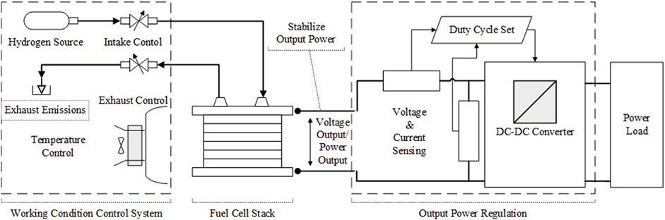
FIGURE 1. Structure of portable fuel cell power system.
With these subsystems checked, the introduced power regulation system is directly connected to the positive and negative output terminals of the stack. The output regulation system includes a fuel cell stack output current/voltage sensor, Micro Controller Unit (MCU), and a buck-based converter circuit. The MCU calculates and sets the duty cycle and changes the equivalent I-V characteristics of the DC-DC circuit.
When compared with dedicated ICs, MCUs and related buck circuits consume more power and have less stability. However, a programmable control unit provides more adjustable space to help the power control rates fit to front-end devices. Moreover, the increased power consumption is not comparable to the output power of the 50 W level. Thus, the fuel cell stack’s output is set and controlled. Additional current and voltage sensors are introduced to carry out circuit function verification and error detection.
Direct connection to the stack terminals can prevent changes in output current from causing a rapid change in hydrogen pressure, which not only causes damage to fuel cell stack’s sealing tightness but also causes difficulties in pressure and temperature stabilizing. Though matching to load is discarded in this structure, the whole structure can be seen as a stable unit. All parts and control logic only respond to its front-end environments. When a change in power load emerges, the power regulation system prioritizes protecting the stack over meeting the load demands. Mismatches in power demand can be compensated through other channels such as energy storage batteries. This greatly improves the safety of the operation of the micro-sized power system.
3 Modeling of system components and control process
The working procedure of the fuel cell output power regulation system is shown in Figure 2. First, according to the user-defined P-set value, an estimated output power value of the fuel cell stack is set. Then, a P-I control algorithm is applied to confirm the duty cycle of the DC-DC circuit, corresponding to the equivalent resistance that will change the fuel cell stack’s output working point in an instant. Therefore, the output current and output power are under control. Finally, this output power flow will go through the DC-DC converter and supply the power load as an actual system power output, with a certain conversion loss.
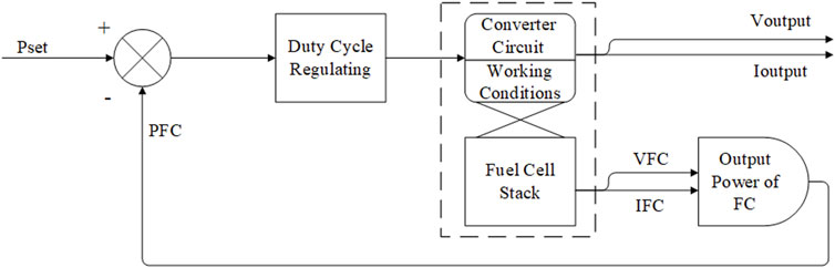
FIGURE 2. Working procedure of fuel cell output power regulation system.
Different from the other power management systems, the whole power regulation system aims at the output power port of the fuel cell stack, where the control variable is the output power value on this port only, therefore some common concepts on power management systems are no longer applicable. Components directly related to the output port have to be modeled and control methods have to be designed according to the characteristics of the fuel cell.
3.1 Modeling of fuel cell stack
The proton exchange membrane fuel cell (PEMFC) is composed of a proton exchange membrane placed between two electrodes coated with the platinum catalyst. The hydrogen and oxygen gases are supplied at the anode and cathode sides, respectively. As the only power generation component, the PEMFC stack is considered the central part of the fuel cell power system, and its output performance determines the output capacity of the system. Generally speaking, the PEMFC could be described as a steady-state model or dynamic model. The steady-state model reflects the relationship between the voltage and current and can be obtained using both analytical and experimental approaches (Arjanaki et al., 2022). The dynamic fuel cell models show the transient performance of the fuel cell by using electrochemical reaction and thermal dynamic equations.
In this article, a simplified PEMFC stack model is presented. The model is based on the steady-state PEMFC model. Usually, the following assumptions can be made (Jia et al., 2009; Puranik et al., 2010):
All stacks are well designed and produced, such that the stack is viewed as a simple superposition of basic units.
The supplied oxygen and hydrogen fuels are pure and their relative humidity is 100% such that the membrane is fully hydrated.
As described in Section 2, in a portable fuel cell power system, the fuel supply and stack temperature are controlled by other control units, so the following assumptions are added:
The cathode and anode temperatures are the same and stable in any unit.
All gases are evenly distributed, and the pressure is stabilized.
Species transport and current transfer across the membrane are stable.
With these assumptions, several factors that usually affect the operation of fuel cells can be simplified. The output electric characteristics can be regarded as an I-V characteristic curve, which corresponds to the output characteristics of an actual cell under control. In model building, some model parameters are built with commonly used theoretical models, while some parameters are based on the actual fuel cell stack, such that the model obtains a better correspondence with the real object. The parameters used in fuel cell model building are listed in Table 1.
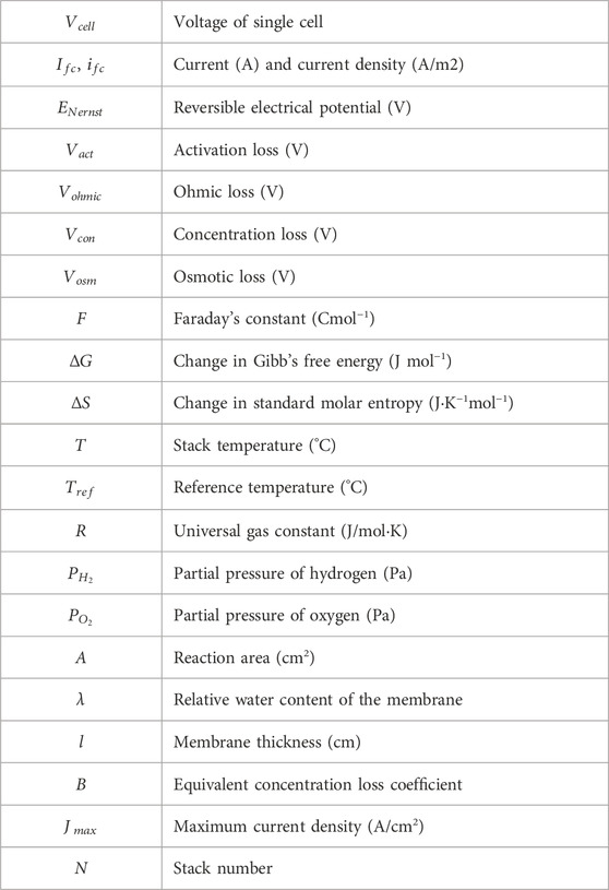
TABLE 1. Fuel cell model parameters.
The voltage of a PEMFC can be described as follows (Pukrushpan et al., 2002; Jia et al., 2009; Kong and Khambadkone, 2009; Puranik et al., 2010):
Subject to the equation above, the output voltage of a single fuel cell could be described as a combination of reversible potential and four voltage losses, which are activation loss, ohmic loss, concentration loss, and osmotic loss.
The reversible electrical potential, also known as Nernst voltage, is theoretically the highest voltage achievable by a single fuel cell. It is determined by the reactions occurring in the cell. The Nernst voltage can be calculated as follows:
The first type of loss in the PEMFC is caused by the slow kinetics of the reaction at the surface of the membrane. The activation loss can be simplified as
where the concentration of oxygen at the cathodic catalytic interface is
Parameters
With all correlation coefficients being stable, parameter
The second type of loss in the PEMFC goes from the voltage drop caused by the equivalent membrane impedance
where the equivalent membrane impedance is
The impedance of the Nafion photon exchange membrane can be calculated by
where the relative water content of the membrane λ is an adjustable parameter.
The third type of loss in the PEMFC is caused by mass transmission. At high current densities, the transmission on the membrane interface becomes the major limit variable. The concentration loss can be described by
The osmotic loss is a type of loss that is usually omitted in a single fuel cell, but in fuel cell stacks, the hydrogen diffused from the other units can reach the cathode interface, causing a voltage loss in the open circuit state. As time goes, the tightness of the fuel cell sealing gradually fails, and this is the main factor of fuel cell stack’s performance degradation.
According to assumptions, a stack is seen as identical cells connected in series. So, the output voltage of a stack is
3.2 Modeling of DC-DC converter
DC-DC converters are widely applied in various power systems. In hybrid power systems, buck or buck–boost converters are used to form standard power rails (Li et al., 2021). By converting the voltage of different power harvesters or generators to the same level, power management strategies can be applied. In these applications, voltage tracking and ripple level at the converter’s output port draws attention (Fekri et al., 2017; Zhu et al., 2017); however, in this power regulation system, the current and voltage properties at the input port affect the fuel cell stack. At the system modeling level, it is the input current variable that interacts with the model of the PEMFC stack. Therefore, the model of the DC-DC converter should be reconstructed into a duty cycle vs. input current model.
The model represents a basic buck converter in the continuous conduction mode. To simulate and estimate the current and voltage changes, an additional set of inductors and capacitors is applied, the topology is shown in Figure 3, where R is the external load and
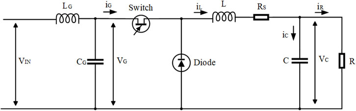
FIGURE 3. Topology of buck converter.
In a working cycle, the circuit, as shown in Figure 3, has two phases: an on phase (0-DTS) and off phase (DTS-TS) (Tan et al., 2005). According to Kirchhoff’s law, the equations in the two phases are as listed below
Regarding all voltage variables being continuous and all current variables can be credited, these variables can be represented using an average during a cycle, with a constant duty cycle:
Combining equations around the input and output ports, we get
A model of the buck converter can be built into a duty cycle vs. input current type.
The model takes in
3.3 System level modeling
With the output characteristics of the PEMFC stack and the conversion function of the DC-DC converter modeled, a comprehensive estimate of the power regulation system can be made. The presented system-level model consists of the PEMFC stack model and DC-DC converter model, which was previously established. A control unit model and power load model are added to simulate the system working procedure. The data connections of each module are shown in Figure 4.
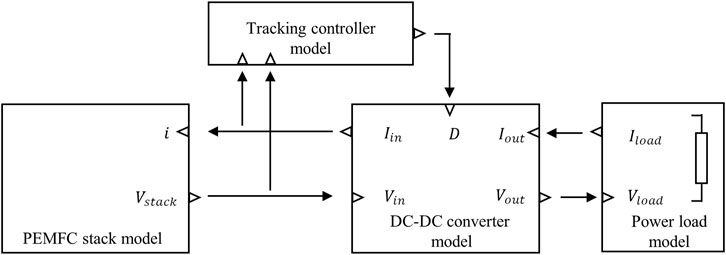
FIGURE 4. Structure of the system-level model.
As shown in Figure 4, the PEMFC stack module has no environment parameters to adjust because all external environments are assumed stable. The only input variable is the stack’s current, which is the current at the input port of the DC-DC converter. This value is gained by the converter module. Likewise, the input voltage of the DC-DC converter is supplied by the PEMFC stack module. The power load module is responsible for generating the energy consumption requirements, loading the multiple load current demands, and including the step signals, periodic signals, continuous growth signals, and voltage linear signals (simulate a purely resistive load). The power tracking controller module simulates the function of sensors and MCUs, a user-defined P-set value is presented, and the model automatically compares the power value with the P-set and calculates the corresponding duty cycle value via a time-separate PI algorithm, to drive the converter module.
4 Simulation results and analysis
The system-level model tests the matching of components and adjustment performance of the PI control, which provides guidance for the actual circuit design. Therefore, the estimation of parameters is closer to the physical needs and is carried out together with the actual circuit design.
In this session, a commercial 100-W proton exchange membrane hydrogen fuel cell stack provided by BCH corporation is selected. This fuel cell stack has a compact appearance, with the output voltage ranging from 22 to 12 V and the output power ranging from 50 to 100 W, which is suitable for portable applications. A self-built hydrogen fuel cell system platform is adjusted to fit this stack. This platform consists of a hydrogen pressure control subsystem and a temperature control system. All parts and control logic are minimized to fit the size and weight constraints. Hydrogen fuel is produced by a electrolyzed-water hydrogen generator instead of a portable hydrogen source, and the pressure at the outlet side of the stack is controlled to about 30–35 kPa by a set of valves. The temperature is controlled to about 35°C–40°C by a single fan.
Driven by this platform, the output characteristics of the fuel cell stack can be tested by changing its output current. The total output current is controlled from 0 A to 6 A, and at each step, 5 min are spent to achieve heat balance. It can be observed that in cycling tests, when the balance is reached at each current, the output characteristics keep fluctuating near a single I-V polarization curve, and we choose test results in the last cycle as the reference for parameter estimation and simulation.
Comprehensively considering the actual test results and widely used theoretical model, the value of the parameters used in the PEMFC stack model is as listed in Table 2.
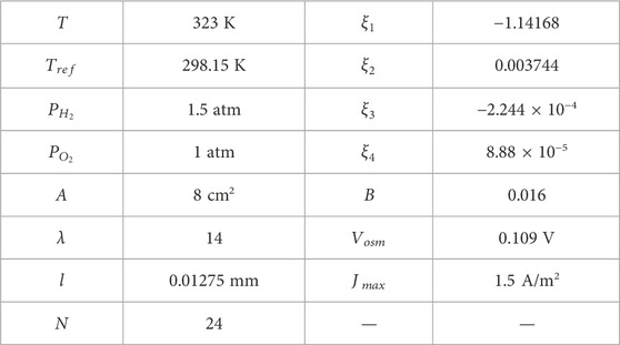
TABLE 2. Parameters used in PEMFC stack model.
Figure 5A shows the polarization curve obtained from simulation and test results. Also, Figure 5B demonstrates the output power vs. output current of the fuel cell stack. It indicates that the simulated curve fits well with the test data at the range 0–5 V, especially at the 3 A current point, where the fuel cell achieves an output power of 45–50 W. In portable applications, such an output power is most widely demanded. Figure 5B also illustrates a monotonous increasing trend of current vs. output power. In the limited output power range, the output power conditions exactly react to the modulation function of the output current.
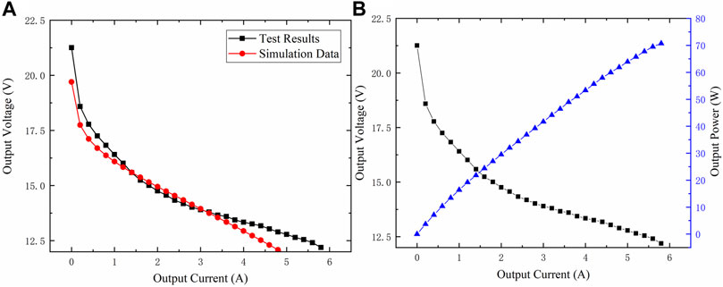
FIGURE 5. Simulation results of fuel cell module and comparison with test results. (A) Polarization curve of simulation and polarization curve of test results. (B) Fuel cell’s output voltage and output power trends.
The module parameters of the DC-DC converter have correspondence with circuit components; parameters L and C are identical to the actual circuit design; and
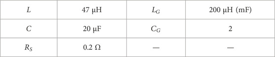
TABLE 3. Parameters used in DC-DC converter model.
The simulation results of the system-level model provide the basis for P-I parameter tuning of the controller. By engineering the tuning method, the system reaches a stable state when the value of parameter P is 0.0036 and I is 0.76, and the control cycle is designed as 1 ms. When the target power level is set to 50 W and variable current and power demands are applied to the load module, the system reacts as follows:
Figure 6A illustrates the power and voltage changes at the fuel cell stack’s output port when the output current demand increases, and Figure 6B shows the change at the converter’s output port. The comparison of powers is shown in Figure 6C. It is proved that the proposed structure achieves its intended function and regulates the fuel cell power to 50 W as the current demands grow. The system fails in the low current environment, which is because the power demand is too low and goes beyond the theoretical matching level. The converter forms direct conduction. This situation is not included in the working range. It is also observed that as the current demands grow, the output voltage at the system output port falls and the power value suffers a decrease as the result of conversion losses. Figure 6D demonstrates a more detailed view: when a step increase occurs at the output power demand (corresponding to a sudden startup of the load), the controller reacts to it and adjusts the duty cycle, and reestablishes a balance in no more than 0.2 s. The simulation results validate the system function and provide guidance for designing the hardware.
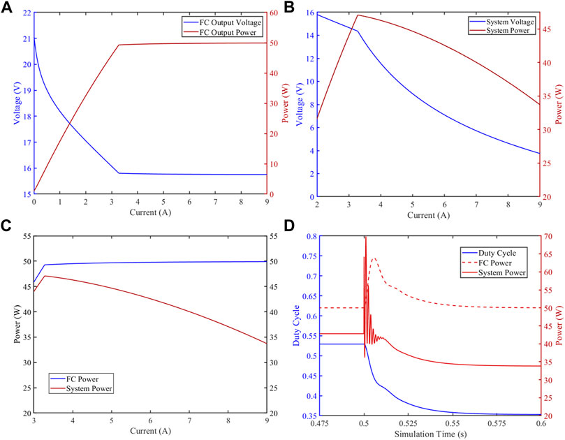
FIGURE 6. Simulation results of the system-level model. (A) Power and voltage changes at the fuel cell stack’s output port. (B) Power and voltage changes at the converter’s output port. (C) Comparison of powers of fuel cell and system output. (D) Transient response of the system.
5 System implementation and test results
Based on the guidance of component selection and tuning of control parameters, a fuel cell power regulation system is designed and implemented. As demonstrated in Section 2, the system takes an MCU as the core, takes a sampling voltage and current, and controls a buck circuit. The output level of the BCH fuel cell stack goes from 18 V to 12 V when the output power is within an expected range, and the converted output voltage of this system is approximately 9–5 V, suitable for mobile phones or other handheld devices.
The structure of the implemented power regulation system is shown in Figure 7 and the actual product is shown in Figure 8. The STM32 MCU is selected and powered by an independent battery. This is for safety reasons. The MAX9923 high-precision side current detection amplifier is applied to gain more accurate current sampling results, voltage, and current levels of the fuel cell stack connection port, and the output port are converted by an ADS8866 ADC, and then sent to the MCU. The MCU generates a 0.2-MHz PWM signal, which controls a Gate Driver IC DGD0506. This IC drives two MOS transistors to control a buck circuit. The inductor and capacitor are 47 μH and 20 μF, respectively; the same as they were in the system-level model. The system is equipped with a communication port with a PC. Additional designs are made to prevent surge currents from damaging the system or fuel cell.
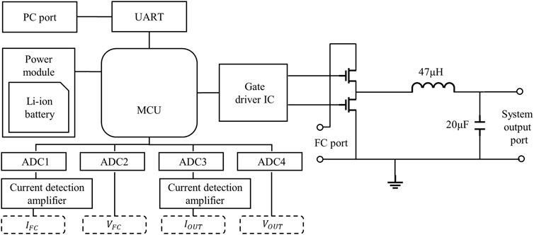
FIGURE 7. Structure of implemented power regulation system.
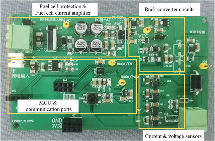
FIGURE 8. Photo of power regulation system.
On the software side, the MCU continuously acquires the current and voltage data at the fuel cell port and runs the PI control process every 1 ms. The calculated duty cycle D has a limit to 95% and is then transmitted to the PWM generator. Voltages and currents at the output port are also monitored, and once an abnormal reading emerges, the system goes into the shutdown mode, and D is set to zero.
To verify that the system circuit board implemented in this article can stabilize the output current and voltage of the fuel cell, the system is connected to a running fuel cell stack and an adjustable electronic power load. The load is set to constant current mode with the current demand near 5 A and then reduces the load current sequentially in steps of 0.2 A to test the output power when the system is set to eight modes, that is, 5 W–40 W power regulation targets. The output power vs. output current test results are shown in Figure 9. The system’s output powers are represented by marked lines and the controlled powers of the stacks are represented by dashed lines. It is observed that the power regulation system board works as the model predicts: the system regulates the output power of the fuel cell stack to a designated value in each active zone and the final output suffers some conversion losses. The average efficiency at 35 W goes up to 85%. The system is competent in regulating the output power of the fuel cells in portable applications, with relatively high efficiency.
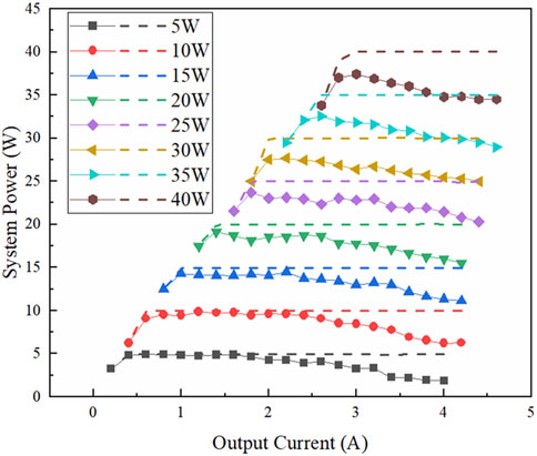
FIGURE 9. System function test results.
6 Conclusion
Creating a quantitative and controlled energy output of the fuel cell stack is a feasible way of reducing complexity and improving safety of a portable micro fuel cell power system. For this purpose, a micro power regulation system is proposed. The system contains a microcontroller, sensors of current and voltage signals, and a controlled DC-DC converter. By sensing and calculating via the microcontroller, the DC-DC converter regulates power through the system. Then, in order to match the selected fuel cell stack, a PEMFC stack model is constructed. This model presents the output electrical characteristics of a fuel cell stack’s standard operation. Besides, an average current and voltage model of the DC-DC converter is constructed to estimate the power regulation function. Furthermore, these models are combined into a system-level model of the whole power regulation system, which can predict the system’s actions. With this, the PI control parameters can be tuned and circuit design references provided. Finally, a board-level power regulation system is implemented on the basis of the abovementioned structures and methods. The system works at a 100-W level compact fuel cell stack to regulate the stack voltage around 18–12 V and provides a 9–5 V voltage output. The performance of this system has been tested, and it was observed that the system fulfills its intended function and regulated the output power to a fixed level of 5 W–40 W, depending on the preset conditions, and achieves good efficiency.
Data availability statement
The raw data supporting the conclusions of this article will be made available by the authors, without undue reservation.
Author contributions
SZ: conceptualization, methodology, software, formal analysis, and writing—original draft. WY: visualization, investigation, and writing—review and editing. XL: methodology, software, and validation. JC: resources, supervision, and funding acquisition. YZ: conceptualization, funding acquisition, resources, supervision, and writing—review and editing.
Funding
This work was supported by the Natural Science Foundation of Heilongjiang Province (No. LH2020F013).
Conflict of interest
The authors declare that the research was conducted in the absence of any commercial or financial relationships that could be construed as a potential conflict of interest.
Publisher’s note
All claims expressed in this article are solely those of the authors and do not necessarily represent those of their affiliated organizations, or those of the publisher, editors, and reviewers. Any product that may be evaluated in this article, or claim that may be made by its manufacturer, is not guaranteed or endorsed by the publisher.
References
Arjanaki, A. A., Kolagar, A. D., and Pahlavani, M. R. A. (2022). A two-level power management strategy in a DC-coupled hybrid microgrid powered by fuel cell and energy storage systems with model predictive controlled interface converter. J. Energy Storage 52, 104861. doi:10.1016/j.est.2022.104861
Barbir, F., and Gomez, T. (1996). Efficiency and economics of proton exchange membrane (PEM) fuel cells. Int. J. Hydrogen Energy 21, 891–901. doi:10.1016/0360-3199(96)00030-4
Fekri, M., Molavi, N., Adib, E., and Farzanehfard, H. (2017). High voltage gain interleaved DC–DC converter with minimum current ripple. IET Power Electron. 10, 1924–1931. doi:10.1049/iet-pel.2016.0675
Fu, Z. M., Li, Z. H., Si, P. J., and Tao, F. Z. (2019). A hierarchical energy management strategy for fuel cell/battery/supercapacitor hybrid electric vehicles. Int. J. Hydrogen Energy 44, 22146–22159. doi:10.1016/j.ijhydene.2019.06.158
Houwing, M., Negenborn, R. R., Ilic, M. D., and De Schutter, B.IEEE (2009). “Model predictive control of fuel cell micro cogeneration systems,” in International Conference on Networking, Sensing and Control, Okayama, JAPAN. NEW YORK, Mar 26-29 2009.
Hsu, S. C., and Liang, S. F.IEEE (2012). “Optimal efficiency of fuel cell/battery hybrid power management,” in 2012 International Conference on Control, Automation and Information Sciences (ICCAIS), Saigon, Vietnam, Nov 26-29 2012, 231–235.
Jia, J., Li, Q., Wang, Y., Cham, Y. T., and Han, M. (2009). Modeling and dynamic characteristic simulation of a proton exchange membrane fuel cell. Ieee Trans. Energy Convers. 24, 283–291. doi:10.1109/tec.2008.2011837
Karami, N., Outbib, R., and Moubayed, N.IEEE (2012). “Fuel flow control of a PEM fuel cell with MPPT,” in IEEE International Conference on Control Applications (CCA) Part of 6th IEEE Multi-Conference on Systems and Control (IEEE MSC), Dubrovnik, CROATIA, Oct 03-05 2012, 289–294.
Kong, X., and Khambadkone, A. M. (2009). Modeling of a PEM fuel-cell stack for dynamic and steady-state operation using ANN-based submodels. Ieee Trans. Industrial Electron. 56, 4903–4914. doi:10.1109/tie.2009.2026768
Lee, J., and Kim, T. (2012). Micro PEM fuel cell system with NaBH4 hydrogen generator. Sensors Actuators a-Physical 177, 54–59. doi:10.1016/j.sna.2011.08.004
Li, M. X., Deng, H. C., Zhang, Y. F., and Hou, C. J. (2021). A small hybrid power system of photovoltaic cell and sodium borohydride hydrolysis-based fuel cell. Micromachines 12, 278. doi:10.3390/mi12030278
Liang, J., and Feng, C. M.IEEE (2007). “Stability improvement of micro-grids with coordinate control of fuel cell and ultracapacitor,” in 38th IEEE Power Electronic Specialists Conference (PESC 07), Orlando, FL. NEW YORK, Jun 17-21 2007, 2472–2477. Ieee, Electron Devices Soc & Reliability Group.
Matsuo, O., Matsuo, H., Tuji, M., Kobayashi, K., and Sekine, Y.IEEE (2006). “A hybrid type DC-DC converter with new control strategy for a micro-fuel cell power supply system,” in 28th International Telecommunications Energy Conference, Providence, RI. NEW YORK, Sep 10-14 2006. Ieee, 1-+.
Minas, C.ASME (2008). “Structural and thermal design challenges of portable micro fuel cell systems,” in ASME International Mechanical Engineering Congress and Exposition, Boston, MA. NEW YORK, Oct 31-Nov 06 2008, 751–756. Amer Soc Mechanical Engineers.
Pukrushpan, J. T., Stefanopoulou, A. G., and Peng, H.ACC & ACC. (2002). “Modeling and control for PEM Fuel Cell stack system,” in 20th Annual American Control Conference (ACC), Anchorage, Ak. NEW YORK, May 08-10 2002, 3117–3122.
Puranik, S. V., Keyhani, A., and Khorrami, F. (2010). State-space modeling of proton exchange membrane fuel cell. Ieee Trans. Energy Convers. 25, 804–813. doi:10.1109/tec.2010.2047725
Ramos, C. A., Romero, A., Giral, R., and Martinez-Salamero, L.IEEE (2007). “Maximum power point tracking strategy for fuel cell power systems,” in 2007 IEEE International Symposium on Industrial Electronics, Vigo, SPAIN, Jun 04-07 2007, 2613–2618.
Tan, S. C., Lai, Y. M., Cheung, M. K. H., and Tse, C. K. (2005). On the practical design of a sliding mode voltage controlled buck converter. Ieee Trans. Power Electron. 20, 425–437. doi:10.1109/tpel.2004.842977
Xie, C. G., Pavio, J., Hallmark, J., Bostaph, J., and Fisher, A. (2002). “Key requirements of micro fuel cell system for portable electronics,” in 37th Intersociety Energy Conversion Engineering Conference (IECEC), Washington, DC, Jul 29-31 2002, 603–606.
Zenith, F., and Skogestad, S. (2007). Control of fuel cell power output. J. Process Control 17, 333–347. doi:10.1016/j.jprocont.2006.10.004
Keywords: micro fuel cell, micro power system, power control, fuel cell stability, DC-DC converter
Citation: Zhong S, Yuan W, Liu X, Cao J and Zhang Y (2023) Output power regulation system for portable micro fuel cell systems. Front. Energy Res. 11:1118743. doi: 10.3389/fenrg.2023.1118743
Received: 07 December 2022; Accepted: 13 February 2023;
Published: 07 March 2023.
Edited by:
Fanglin (Frank) Chen, University of South Carolina, United StatesReviewed by:
Shubin Zhang, Jiangnan University, ChinaLonglu Wang, Nanjing University of Posts and Telecommunications, China
Yuewu Huang, Harbin University of Science and Technology, China
Copyright © 2023 Zhong, Yuan, Liu, Cao and Zhang. This is an open-access article distributed under the terms of the Creative Commons Attribution License (CC BY). The use, distribution or reproduction in other forums is permitted, provided the original author(s) and the copyright owner(s) are credited and that the original publication in this journal is cited, in accordance with accepted academic practice. No use, distribution or reproduction is permitted which does not comply with these terms.
*Correspondence: Yufeng Zhang, eXVmZW5nX3poYW5nQGhpdC5lZHUuY24=