 Rui He
 Yanan Wu
 Jing Lu
 Jun Li1
 Junmin Zhang
95% of researchers rate our articles as excellent or good
Learn more about the work of our research integrity team to safeguard the quality of each article we publish.
Find out more
ORIGINAL RESEARCH article
Front. Energy Res. , 16 February 2023
Sec. Process and Energy Systems Engineering
Volume 11 - 2023 | https://doi.org/10.3389/fenrg.2023.1112210
This article is part of the Research Topic Planning and Operation of Hybrid Renewable Energy Systems, Volume II View all 12 articles
Tokamak is a promising device for using nuclear fusion energy, and the triggering of Tokamak power supply has the characteristics of extreme asymmetry and drastic instantaneous change, which bring spectrum-rich harmonics to the DC side of the power supply, threatening the operational safety of the device. Although the harmonic analysis method of the DC side already exists, however, it still has the problem of cumbersome and inaccurate calculation when it is oriented to fusion power systems with complex operation modes. Based on the three-phase unified switching function, this paper introduces delay factor, and establishes a non-linear function model of converter suitable for the case of asymmetrical triggering. According to the principle of the switching function method, the frequency domain equation of the proposed model is obtained, then combined with power grid parameters, the harmonic analysis of the DC side can be derived. The correctness of the theoretical analysis is verified by comparing the calculation results with the harmonic frequency spectrum data obtained by direct Fourier decomposition of the DC side voltage.
Fusion energy could be the ultimate solution to the world energy crisis. Tokamak is the most promising magnetic confinement fusion device that has been adopted worldwide. Superconducting magnet is one of the most complex and important core components of the Tokamak device, and quench phenomenon can easily lead to the burning of the magnet, resulting in tens of millions of economic losses (Wang K et al., 2020; Lopes et al., 2021; Gorit et al., 2022). Accurate and effective quench detection is an important prerequisite for quench protection, which is crucial to the long-term safe and stable operation of the Tokamak device (Wang et al., 2018; Risse et al., 2019). To respond to the requirements of plasma millisecond-level fast control and variable magnetic field, the trigger control mode of converter of the Tokamak power supply exhibits the characteristic of extreme asymmetry and drastic instantaneous change (Xiong et al., 2021; Liu et al., 2022). This will bring a large number of sidelobe-rich, fast-changing non-characteristic harmonics on the superconducting magnet, which will drown the real quench signal, increase the risk of false alarms in quench detection, and affect the safe and stable operation of the Tokamak device (Lu et al., 2018; Wang Z M et al., 2020). In addition, the resonance phenomenon of the harmonics on the DC side will induce an inhomogeneous voltage distribution. It might even produce voltages high enough to damage the insulation between the superconducting magnet (Meguro et al., 2020; Sonoda et al., 2022).
At present, the generation and distribution of voltage harmonics in DC side of the Tokamak power supply are rarely studied. Hu and Yacamini (2016) first established the switching function, and analyzed the generation and conversion principle of 6kth harmonics on the DC side based on Fourier decomposition of the switching function, but did not analyze the non-characteristic subharmonics in the case of the asymmetrical triggering; Yang et al. (2009) uses the switching function method to analyze the voltage harmonics of DC side in the case of the asymmetrical triggering, but the function model used is relatively ideal, and the commutation overlap angle is not taken into account; Chen et al. (2022) improved the switching function, considered the commutation process, and proposed a more accurate three-phase unified switching function, but lacked further research on the trigger offset. Compared with direct Fourier decomposition of DC side voltage, the switching function method used in the above paper can simplify the harmonic analysis process and reduce the calculation amount because it uses a simple triangular transformation to replace the piecewise integration, and is more suitable for the working condition of rapid harmonic change of fusion power supply (Hu and Morrison, 1997). However, none of the models used in the switching function method can accurately describe the commutation process of the converter under an asymmetrical triggering, so it is also difficult to complete the analysis of voltage harmonics on the DC side.
This paper is organized as follows. Section 2 describes the composition of the poloidal field power supply of the EAST (Experimental Advanced Superconducting Tokamak) and analyzes the relationship between its output and the three-phase full-bridge controlled rectifier circuit. Based on the three-phase unified switching function, section 3 considers the influence of the asymmetrical triggering, introduces the delay factor, and establishes the non-linear function model of the converter suitable for the case of the asymmetrical triggering. In section 4, the frequency domain equation of the non-linear function model of the converter is obtained, then combined with power grid parameters, the DC side harmonic under asymmetrical triggering is analyzed and the calculation formula is derived. In section 5, the correctness of the theoretical analysis of section 4 is verified by comparing the calculation results with the harmonic frequency spectrum data obtained by direct Fourier decomposition of the DC side voltage. Finally, some discussions and conclusions are summarized in sections 6 and 7. The flow chart of harmonic analysis on DC side is shown in Figure 1.
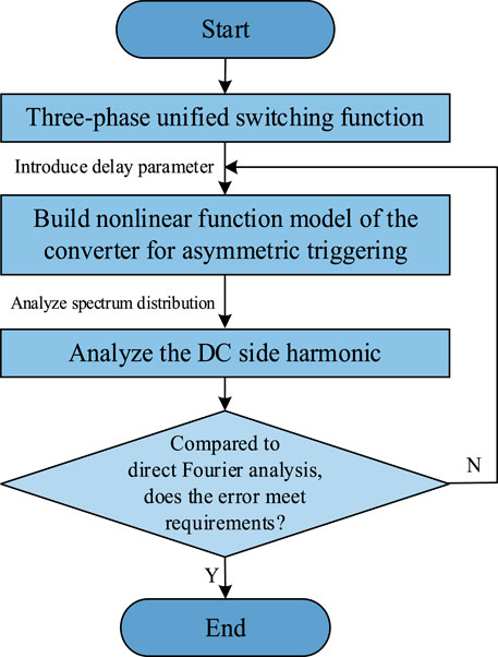
FIGURE 1. Flow chart of harmonic analysis on DC side.
This paper takes the Tokamak power supply as the research object. In the EAST device, the four-quadrant thyristor converter is used as the poloidal field power supply to provide ±15 kA DC current to the magnet (Chen et al., 2016), as shown in Figure 2.
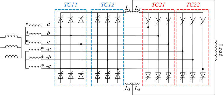
FIGURE 2. The four-quadrant thyristor converter in the EAST poloidal field.
Its basic unit is a three-phase full-bridge controlled rectifier circuit, as shown in Figure 3, in the figure: ua, ub, uc are three-phase voltages; ia, ib, ic are three-phase currents; ud and id are the voltage and current of the DC side. R is the equivalent resistance and L is the equivalent inductance.
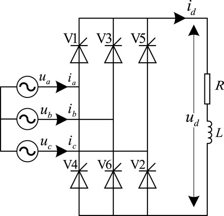
FIGURE 3. Three-phase full-bridge controlled rectifier circuit.
In an ideal situation, the AC(Alternating Current) power supply can be considered as a three-phase symmetrical industrial frequency sine wave voltage, and the harmonics of the power supply itself are ignored (Liu et al., 2020; Liu et al., 2022). When the device is in a stable working state, the three-phase phase voltage is expressed as in Equation 1.
where Um is the voltage amplitude, ω = 2π/T is the angular frequency, and T is the period.
In the EAST poloidal field four-quadrant thyristor converter, except PS(Power Supply)7, PS8 power supply, the difference between the two windings on the valve side of PS1, 2, 3, 4, 5, 6, 9, 10 and 11, 12 power supply is π rad. The forward converter is composed of TC(Thyristor Converter)11 and TC12 two groups of three-phase full-bridge controlled rectifier circuit, and the reverse converter is composed of TC21 and TC22, which are connected to the two valve side windings of the transformer respectively. The in-phase anti-parallel structure is formed during high current operation, and the DC side output of the superconducting magnet power supply for Tokamak is equivalent to the superposition of the outputs of two three-phase full-bridge controlled rectifier with a phase difference of π rad (Chen et al., 2016; Wang et al., 2019).
Next, we take the three-phase full-bridge controlled rectifier as an example to study, and then consider the phase relationship between the primary and secondary sides of the converter transformer and then superimpose it.
Since the commutation process cannot be completed instantaneously in the actual situation, Chen et al. (2022) further considers the commutation overlap angle γ on the basis of the traditional switching function, and obtains a three-phase unified switching function. On this basis, the natural commutation point is used as the starting point for calculating the firing angle α of each thyristor, and the expression of the non-linear function model of the converter fi (i = 1,2,3,4,5,6) of the rectifier circuit is obtained as Equation 3
Where
The time domain waveform diagram of the non-linear function model of the converter fi (i = 1,2,3,4,5,6) in the case of the asymmetrical triggering is shown in Figure 4.
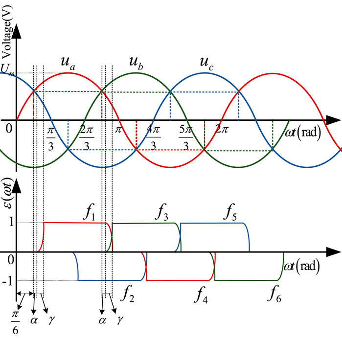
FIGURE 4. The time domain waveform diagram of three-phase voltage and the non-linear function model of converter under symmetrical triggering.
To meet the requirements of the current feedback control of the superconducting magnet, the fusion converter must be able to switch the angle quickly within the firing angle range, so the conduction time of each thyristor is different. When the firing angle of one of the six thyristors changes, only the non-linear function model of itself and its previous thyristor changes correspondingly, while the rest do not change. For example, the firing angle of a certain thyristor lags behind the normal firing angle of σ degrees. Affected by this, the non-linear function model of the previous thyristor will also change correspondingly, and its conduction time will be extended by the angle of σ. If the firing angle is ahead of the normal conduction angle, you can substitute -σ into the calculation, and other analysis procedures are the same.
Assuming that the conduction time of a thyristor will be shortened under the condition of the firing angle delay, the non-linear function model of the converter is fi-, and its expression is:
Where
Because of the triggering delay of the latter thyristor, the conduction time of the former thyristor will inevitably become longer. Let the non-linear function model of this thyristor be fi+, and its expression is:
Where
The time domain waveform diagram of the non-linear function model of the converter fi (i = 1,2,3,4,5,6) in the case of the asymmetrical triggering is shown in Figure 5.
FIGURE 5. The time domain waveform diagram of three-phase voltage and the non-linear function model of converter under asymmetrical triggering.
The general method to analyze the harmonic characteristics of a non-sinusoidal periodic voltage (or current) is to directly perform Fourier decomposition on it. But to integrate the voltage or current in a cycle to calculate the Fourier coefficient, the operation process is complicated and the amount of operation is large. Because the converter equipment has discrete sampling and modulation switching characteristics, the piecewise integration can be replaced by a simple triangular transformation, which can simplify the analysis process of the converter equipment related waveforms. This method of harmonic analysis for steady-state operation of converter equipment is called switching function method.
Fourier analysis of the non-linear function model of converter fi (i = 1,2,3,4,5,6) is performed according to the definition:
Among them, a0, an, bn are Fourier coefficients, and using the orthogonality of trigonometric functions, the calculation formulas of a0, an, bn can be obtained as:
The DC side voltage waveform of the converter is the result of modulating the AC voltage by the non-linear function model of the converter, During normal operation, each converter valve is triggered and turned on in turn at equal intervals, and the output DC voltage ud is formed by modulating the input three-phase AC voltages ua, ub, uc by the non-linear function models of converter f1∼f6:
Fourier decomposition is performed on the proposed model fi according to the principle of switching function method under the symmetrical triggering. a0, an, bn are calculated and substituted into Equation 6, and the sine and cosine terms of the same frequency are combined to obtain:
In the equation, Aj and φj (j = 1,2,3,4,5,6,7) are as follows, where A4 = -A3, A6 = -A5. when n is 1 in Equation 9, the denominator of A5 and A6 will be zero, the equation will become meaningless. At this time, only limit operation needs to be done, that is, use
Fourier decomposition is performed on fi- and fi+ in the same way under asymmetrical triggering.
Where Q1, Q2, Q3, Q4, Bj, Cj and θj, ηj (j = 1,2,3,4,5,6,7) are as follows, B2 = A2, θ2 = φ2, B4 = A4, θ4 = φ4, B6 = A6, θ6 = φ6, C1 = A1, η1 = θ1, C3 = A3, η3 = θ3, C5 = A5, η5 = θ5, η7 = θ7:
When n is 1 in Equation 10, the denominator of B5 and B6 will be zero, the equation will become meaningless. At this time, only limit operation needs to be done, that is, use
When n is 1 in Equation 11, the denominator of C5 and C6 will be zero, the equation will become meaningless. At this time, only limit operation needs to be done, that is, use
First, according to Equation 7, calculate the values of a0, a1, b1 when n is 1, and substitute them into Equation 6. Combined with Equation 8, it is found that the result of modulating the AC voltage by the fundamental component of the non-linear function model of the converter does not change with time, that is, the DC component in the output voltage, and its expression is Equation 12.
When n is a positive integer that is not equal to 1, combine Equation 2 to obtain f1-f4, f3-f6, f5-f2 and substitute them into Equation 8 to obtain:
When the harmonic order n of the non-linear function model of the converter is 5, 11, 17... 6k-1 (k = 1, 2, 3...) times, the DC side will generate n+1st harmonics:
When the harmonic order n of the non-linear function model of the converter is 7, 13, 19... 6k+1 (k = 1, 2, 3...) times, the DC side will generate n-1st harmonics:
In Equations (13) and (14) Dj = Aj Rj, where Rj, ϕj are as follows:
From Eqs. 13, 14, it can be known that the n = 6k±1st harmonic of the non-linear function model of the converter modulates the AC voltage so that the DC side only contains the 6kth characteristic harmonic component in addition to the DC component. Therefore any 6kth harmonics on the DC side can be regarded as the superposition of un+1 at n = 6k-1 and un-1 at n = 6k+1.
If σ = 0 in Eqs. 4, 5, it can be seen the expression is the same as that when the trigger signal is symmetrical, so the symmetrical triggering operation is regarded as a special case of the asymmetrical triggering operation. In the case of asymmetrical triggering, the non-linear function model of converter has changed greatly, and various harmonic components have appeared. At this time, the voltage on the AC side may be affected by this, and various non-characteristic subharmonics will be generated on the DC side.
Randomly select one of the thyristors for discussion. For example, the firing angle of thyristor 3 lags behind the normal firing angle σ degrees. Affected by this, the conduction time of thyristor 1 will be extended by σ angle. The time domain waveform diagram of the non-linear function model of converter fi (i = 1,2,3,4,5,6) in this case is shown in Figure 6.
FIGURE 6. The time domain waveform diagram of three-phase voltage and the non-linear function model of converter under thyristor 3 lags behind σ degrees.
According to the same principle of Equation 8, the expression of the output DC voltage ud’ during asymmetrical triggering is Equation 15:
ud’ can also be expressed as:
Where:
It can be seen that in the case of the asymmetrical triggering, the DC side voltage ud’ will still contain the harmonic components in the symmetrical case ud. Since the output voltage in the case of the symmetrical triggering has been analyzed before, we will only analyze the non-characteristic harmonics of the DC side Δud caused by the asymmetrical moment. The harmonics of the final output voltage can be summed up by the ud and Δud.
According to equation 9 and 11, f1+-f1 is obtained by calculation:
Where E, Sj and ζj (j = 1,2,3,4,5,6,7)are as follows:
According to equation 9 and 10, f3--f3 is obtained by calculation:
Where F, Tj and ξj (j = 1,2,3,4,5,6,7) are as follows:
Substitute f1+-f1, f3--f3 into Equation 16 to get:
Where
It can be seen from Equation 19 that when the harmonic order n of the non-linear function model of the converter is an even number of 2k (k = 1, 2, 3 … ), the DC side will generate 2k±1st odd order voltage harmonics; when n is an odd number of 2k+1 (k = 1, 2, 3 … ), the DC side will generate 2kth and 2k+2nd even order voltage harmonics. The calculation formula of DC side voltage harmonics can be derived as follows:`
In Equation 20, Δuz represents the DC component of the DC side voltage, which is formed by Δud3 when n = 1; Δu1 represents the fundamental component of the DC side voltage, which is formed by the superposition of Δud1 and Δud3 when n = 2; Δu2k represents the even-order harmonic component of the DC side voltage, which is formed by the superposition of Δud2 at n = 2k-1 and Δud3 at n = 2k+1; Δu2k+1 represents the odd-order harmonic component of the DC side voltage, which is formed by the superposition of Δud2 at n = 2k and Δud3 at n = 2k+2.
Substitute the circuit parameters of the power grid and the converter into the DC side harmonic calculation formula, and calculate the theoretical value of the harmonic frequency spectrum data in MATLAB. It is compared with the frequency spectrum data obtained by direct Fourier decomposition of the DC side voltage data to verify the accuracy of the harmonic analysis in this paper.
Taking the PS9 power supply of the poloidal field of the EAST device as an example, the effective value of the three-phase voltage input by the power grid is 259.3 V, the amplitude Um is 366.7 V, and the frequency is industrial frequency 50 Hz. Taking the power supply system under rapidly rising and changing current demands still operating in steady state as a reference, when the converter works in the inverter state, if the firing angle delay is too large, it will easily lead to commutation failure. Therefore, the range of firing angle α is generally between π/9 rad to 13π/18 rad. Correspondingly, the range of commutation overlap angle γ is generally between 8π/180 rad to π/10 rad, and the range of deviation angle σ is generally between 0 rad to 2π/9 rad (Wang Z M et al., 2020). As shown in Tab.1, select operating parameters at equal intervals according to the above range, and 8 cases are set to verify the harmonic analysis in this paper.
TABLE 1. Main parameters of the system.
Based on equations (13) and (14), the harmonic voltages on the DC side of the converter under symmetrical triggering conditions can be obtained. Table 2 and Figure 7 show the comparison of calculation results of the DC side harmonic formula (Method A) and the direct Fourier decomposition (Method B) under the conditions of Cases 1 to 4.
TABLE 2. Calculation results under the conditions of Cases 1 to 4.
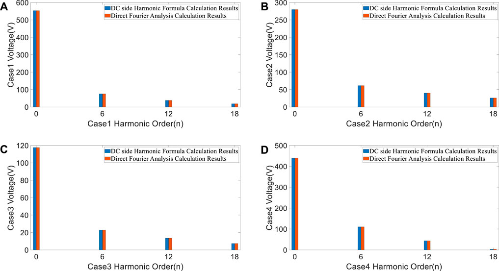
FIGURE 7. The comparison of calculation results of the DC side harmonic formula and the direct Fourier decomposition: (A) α = π/9, γ = 8π/180, σ = 0, ωt = 3π/5. (B) α = 57π/180, γ = 11π/180, σ = 0, ωt = 5π/5. (C) α = 94π/180, γ = π/12, σ = 0, ωt = 7π/5. (D) α = 13π/18, γ = π/10, σ = 0, ωt = 9π/5.
It can be seen from Table 2 and Figure 7 that the output voltage only contains 6kth characteristic harmonics under the symmetrical triggering condition, and the values of the voltage harmonics are equal.
Based on Equation 20, the harmonic voltages on the DC side of the converter under asymmetrical triggering conditions can be obtained. Table 3 and Figure 8 show the comparison of calculation results of the DC side harmonic formula (Method A) and the direct Fourier decomposition (Method B) under the conditions of Cases 5 to 8.
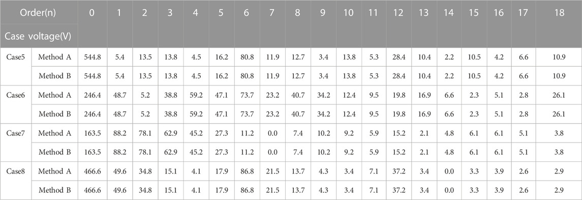
TABLE 3. Calculation results under the conditions of Cases 5 to 8.
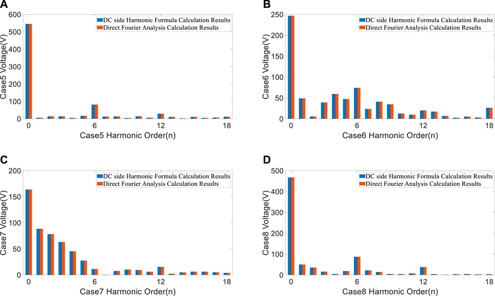
FIGURE 8. The comparison of calculation results of the DC side harmonic formula and the direct Fourier decomposition: (A) α = π/9, γ = 8π/180, σ = π/18, ωt = 3π/5. (B) α = 57π/180, γ = 11π/180, σ = π/9, ωt = 5π/5. (C) α = 94π/180, γ = π/12, σ = π/6, ωt = 7π/5. (D) α = 13π/18, γ = π/10, σ = 2π/9, ωt = 9π/5.
It can be seen from Table 3 and Figure 8 that the output voltage not only contains 6kth characteristic harmonics but also includes various non-characteristic harmonics under the asymmetrical triggering condition, and the values of the voltage harmonics are equal.
Direct Fourier decomposition of the DC side voltage is a traditional and common method for analyzing the spectrum distribution of the DC side, its calculation results are an important reference for verifying the correctness of the analysis. Table 2 and Table 3 shows that the calculation results of the two methods are consistent with each other under the symmetrical trigger condition and asymmetrical trigger condition. So, the proposed method can accurately calculate the harmonic components of the DC side voltage, which verifies the accuracy of the analysis. This paper provides a simple and accurate method for the analysis and calculation of DC side harmonics. Analysis results can provide theoretical guidance for targeted harmonic suppression. It is conducive to reduce the risk of false alarm of quench detection and malfunction of quench protection, and to support the stable operation of the Tokamak.
In this paper, a non-linear function model of converter suitable for the asymmetrical triggering is established, so that the switching function method, which has the advantages of simplifying the analysis process and reducing the amount of calculation, can complete the DC side harmonic analysis and calculation under the asymmetrical triggering of Tokamak power supply.
1) The harmonic relationship between the DC side voltage and the non-linear function model of the converter is clarified: in the case of the symmetrical triggering, the DC side only contains 6kth harmonics, which are superimposed by the 6k+1st and 6k-1st harmonics of the non-linear function model of converter. In the case of the asymmetrical triggering, the odd-order harmonics on the DC side are composed of the even-order harmonics of the non-linear function model of the converter, and the even-order harmonics on the DC side are composed of the odd-order harmonics of the non-linear function model of the converter;
2) The calculation formula of DC side voltage harmonics is deduced, and the quantitative relationship between each harmonic voltage value and AC side voltage value Um, firing angle α, commutation overlap angle γ and deviation angle σ is clarified. The calculation results of this formula are compared with the harmonic frequency spectrum data obtained by direct Fourier decomposition of the DC side voltage data, which verifies the accuracy of the harmonic analysis in this paper.
The original contributions presented in the study are included in the article/supplementary material, further inquiries can be directed to the corresponding author.
RH, project administration, formal analysis, validation, software, writing original draft. YW share first authorship: conceptualization, resources, methodology, funding acquisition. JLu is the corresponding author: investigation, formal analysis, data curation, funding acquisition. JLi, conceptualization, methodology, revision. JZ and YT and PW, software, revision, read. All authors agree to be accountable for the content of the work.
This work was supported by the NSFC (Natural Science Foundation of China) under Grant 52177165, NSFC under Grant 52007184, Youth Innovation Promotion Association of the Chinese Academy of Sciences under Grant 2020440, Natural Science Foundation of Anhui Province under Grant 2108085UD10, Comprehensive Research Facility for Fusion Technology Program of China under Contract No. 2018-000052-73-01-001228.
The authors declare that the research was conducted in the absence of any commercial or financial relationships that could be construed as a potential conflict of interest.
All claims expressed in this article are solely those of the authors and do not necessarily represent those of their affiliated organizations, or those of the publisher, the editors and the reviewers. Any product that may be evaluated in this article, or claim that may be made by its manufacturer, is not guaranteed or endorsed by the publisher.
Chen, X. J., Fu, P., Huang, L. S., Gao, G., and He, S. Y. (2016). Hardware-in-the-loop simulation of the EAST PF converter for PF control system upgrade. Fusion Eng. Des. 112, 57–66. doi:10.1016/j.fusengdes.2016.07.020
Chen, X., Ma, J. P., Wang, S. L., Liu, T. Q., Liu, D., and Zhu, T. Y. (2022). An accurate impedance model of line commutated converter with variable commutation overlap. Ieee Trans. Power Deliv. 37 (1), 562–572. doi:10.1109/Tpwrd.2021.3064985
Gorit, Q., Nicollet, S., Lacroix, B., Louzguiti, A., Topin, F., Torre, A., et al. (2022). Thermal hydraulic analysis of JT-60sa TFC02 complementary quench tests in CTF. Ieee Trans. Appl. Supercond. 32 (6), 1–5. doi:10.1109/Tasc.2022.3171738
Hu, L. H., and Morrison, R. E. (1997). The use of modulation theory to calculate the harmonic distortion in HVDC systems operating on an unbalanced supply. Ieee Trans. Power Syst. 12 (2), 973–980. doi:10.1109/59.589796
Hu, L. H., and Yacamini, R. (1992). Harmonic transfer through converters and HVDC links. Ieee Trans. Power Electron. 32 (3), 514–525. doi:10.1109/63.145139
Liu, X. K., Grassi, F., Spadacini, G., and Pignari, S. A. (2020). Physically based modeling of hand-assembled wire bundles for accurate EMC prediction. Ieee Trans. Electromagn. Compat. 62 (3), 914–922. doi:10.1109/Temc.2019.2922455
Liu, X. K., Wu, B. B., and Xiu, L. C. (2022). A fast positive-sequence component extraction method with multiple disturbances in unbalanced conditions. Ieee Trans. Power Electron. 37 (8), 8820–8824. doi:10.1109/Tpel.2022.3161734
Liu, X. K., Xiong, L. S., Wu, B. B., Qian, Y., and Liu, Y. H. (2022). Phase locked-loop with decaying DC transient removal for three-phase grids. Int. J. Electr. Power and Energy Syst. 143, 108508. doi:10.1016/j.ijepes.2022.108508
Lopes, C. R., Zito, P., Zignani, C. F., Messina, G., Morici, L., Tomassetti, G., et al. (2021). Design optimization for the quench protection of DTT's superconducting toroidal field magnets. Fusion Eng. Des. 172, 112748. doi:10.1016/j.fusengdes.2021.112748
Lu, J., Fu, P., Li, J., Mao, H. F., Shen, X. S., Xu, L. W., et al. (2018). A new hybrid filter based on differential current control method for low-order harmonic suppression in Tokamak power system. Int. J. Energy Res. 42 (1), 82–90. doi:10.1002/er.3829
Meguro, H., Nakamura, K., Shogo, S., Nasu, K., Murakami, H., and Kizu, K. (2020). Effects of resonance phenomenon caused by power supply on JT-60sa CS. Ieee Trans. Appl. Supercond. 30 (4), 1–5. doi:10.1109/Tasc.2020.2970392
Risse, K., Rummel, T., Monnich, T., Ftillenbach, F., Bosch, H. S., and Team, W.-X. (2019). Updates on protection system for Wendelstein 7-X superconducting magnets. Fusion Eng. Des. 146, 910–913. doi:10.1016/j.fusengdes.2019.01.111
Sonoda, S., Nakamura, K., Hirose, Y., Yuinawa, K., Murakami, H., Hamada, K., et al. (2022). Investigation of transient response caused by power supply on JT-60sa central solenoid. Ieee Trans. Appl. Supercond. 32 (6), 1–4. doi:10.1109/Tasc.2022.3151038
Wang, J. J., Huang, Y. Y., Fu, P., Wu, Y. A., and Shen, X. S. (2019). Stability analysis for the voltage of EAST loads based on the short circuit capacity. Fusion Eng. Des. 149, 111355. doi:10.1016/j.fusengdes.2019.111355
Wang, K., Song, Z. Q., Fu, P., Li, H., Tong, W., Wang, S. S., et al. (2020a). Analysis and design of fast discharge resistor system based on forced-air cooling method. Ieee Trans. Plasma Sci. 48 (2), 542–553. doi:10.1109/Tps.2019.2961095
Wang, T., Hu, Y. L., Liu, H. J., Wu, Y., Shi, Y., Pan, C., et al. (2018). Quench detection design for CFETR CSMC. Fusion Sci. Technol. 74 (3), 229–237. doi:10.1080/15361055.2017.1415613
Wang, Z. M., Fu, P., Hang, L. S., Song, Z. Q., Zhang, X. Q., Deng, T. B., et al. (2020b). Preliminary design of high power magnet converter for CRAFT. Plasma Sci. Technol. 22 (4), 045604. doi:10.1088/2058-6272/ab7472
Xiong, L. S., Liu, L., Liu, X. K., and Liu, Y. H. (2021). Frequency trajectory planning based strategy for improving frequency stability of droop-controlled inverter based standalone power systems. Ieee J. Emerg. Sel. Top. Circuits Syst. 11 (1), 176–187. doi:10.1109/Jetcas.2021.3052006
Keywords: fusion energy, tokamak, power supply, harmonic analysis, asymmetrical triggering
Citation: He R, Wu Y, Lu J, Li J, Zhang J, Tian Y and Wang P (2023) Harmonic analysis on direct-current side of tokamak power supply under asymmetrical triggering. Front. Energy Res. 11:1112210. doi: 10.3389/fenrg.2023.1112210
Received: 30 November 2022; Accepted: 16 January 2023;
Published: 16 February 2023.
Edited by:
Liansong Xiong, Xi’an Jiaotong University, ChinaReviewed by:
Haitao Li, Shandong University of Technology, ChinaCopyright © 2023 He, Wu, Lu, Li, Zhang, Tian and Wang. This is an open-access article distributed under the terms of the Creative Commons Attribution License (CC BY). The use, distribution or reproduction in other forums is permitted, provided the original author(s) and the copyright owner(s) are credited and that the original publication in this journal is cited, in accordance with accepted academic practice. No use, distribution or reproduction is permitted which does not comply with these terms.
*Correspondence: Jing Lu, bHVqaW5nQGlwcC5hYy5jbg==
Disclaimer: All claims expressed in this article are solely those of the authors and do not necessarily represent those of their affiliated organizations, or those of the publisher, the editors and the reviewers. Any product that may be evaluated in this article or claim that may be made by its manufacturer is not guaranteed or endorsed by the publisher.
Research integrity at Frontiers
Learn more about the work of our research integrity team to safeguard the quality of each article we publish.