 Xiuping Wang
 Wanming Liu
- School of Electric Power, Shenyang Institute of Engineering, Shenyang, China
Hybrid excitation primary permanent magnet linear motor has the dual advantages of high thrust density of primary permanent magnet linear motor and the flexibility on adjusting the air gap magnetic field of hybrid excitation motor. In this paper, two new 36/4 hybrid excitation primary permanent magnet linear motors with different secondary structures are proposed. Based on the detailed introduction of the motor topology and operation mechanism, the structural parameters are optimized, and the pole arc coefficient of the primary pole shoe and the secondary are finally determined to be 0.4. The secondary is magnetoresistive, and the final thrust adjustment range is about 16.8% under the conditions of optimal armature current and current lead angle. The temperature field of the motor in the magnetizing state is analyzed. The results show that the temperature of the motor decreases gradually from the center to both sides after 7200 s of operation of the new hybrid excitation structure, while the permanent magnet will not be demagnetized permanently. It shows an acceptable reliability.
1 Introduction
With the expansion and development of the central area of the city, under the requirements of a fast and comfortable riding environment, wheel rail trains such as subway vehicles using traditional rotating motors are always subject to physical adhesion restrictions, and have gradually failed to meet the new needs of urban rail transit (Lv, 2020). Primary permanent magnet linear motor (PPMLM) is a device that realizes electromechanical energy conversion based on the principle of magnetic field modulation (i.e., magnetic gear effect), and it benefits from the characteristics of high magnetic energy product and low energy loss of rare earth permanent magnets, which leads to the advantages of high power density and high efficiency (Zhou et al., 2021). Because of its simple structure, high efficiency and energy saving, fast dynamic response, it gains low speed and high thrust, and is particularly suitable for the field of urban rail transit (Shen and Lu, 2021). However, the air gap magnetic field of PPMLM is determined by the magnetic characteristics of the permanent magnet and magnetic circuit structure. There is only a single permanent magnet excitation source inside. As long as the structure is determined, the air gap magnetic field cannot be flexibly adjusted. Therefore, it is a common concern in the electrical field to explore a new high-performance motor system with high thrust density and wide thrust adjustment range. According to this situation, the primary hybrid excitation permanent magnet straight linear motor has attracted extensive attention of scholars at home and abroad in recent years because of its internal combination of permanent magnet and electric excitation of two excitation sources, which makes the air gap magnetic field be easy to adjust and gets a wider adjustment range of thrust.
The primary permanent magnet linear motor was modularized by professor Zhao Wenxiang of Jiangsu University, et al. With this structure, the back EMF of the motor is very sinusoidal and symmetrical, and the thrust fluctuation is quite small (Du et al., 2020). Besides, fault-tolerant teeth are also applied to the structure of the permanent magnet motor, which enhances the independence of each phase and improves the fault tolerance performance of the motor (Zhao et al., 2020). At the same time, the fault-tolerant control strategy when the motor fails are studied (Cheng et al., 2019).
Professor Lu Qinfen of Zhejiang University, et al., added the DC biased sinusoidal current to the armature current of the concentrated winding of the hybrid excitation double salient permanent magnet linear motor, which not only saved the space for adding the isolated DC excitation winding, but also revealed the thrust generation mechanism from the perspective of the magnetic field modulation theory, in which the air gap harmonics were analyzed and calculated. The proposed hybrid excitation permanent magnet linear motor is comprehensively studied (Shen et al., 2021). For polyphase structure, fault-tolerant teeth are introduced into the structure, a nine phase modular hybrid excitation linear motor is proposed, and its electromagnetic performance is analyzed (Zeng et al., 2017).
Qu Ronghai, professor of Huazhong University of Science and Technology, et al. proposed a new type of hybrid excitation flux reverse motor by introducing a DC excitation winding into the alternating pole flux reverse motor in order to adjust the excitation field more flexibly without reducing the torque (Gao et al., 2016). In addition, they proposed a hybrid-excited magnetic gear with eccentric magnet structure. This structure can not only improve the magnetic flux density waveform of the inner air gap but also reduce the harmonic distortion rate, which provides a method to improve the transmission stability torque density of magnetic gears (Jing et al., 2020).
The structure of linear motor and rotary motor are inseparable and mutually reinforcing. The arrangement of permanent magnet arrays and the topology of motor stator and rotor are diverse. The arrangement position of the excitation winding needs to be reasonably arranged according to the topology of the motor, so the arrangement position of the excitation winding is also diverse (Okada et al., 2019; Wu et al., 2021; Zhao et al., 2021). In the reference (Ullah et al., 2021), the author proposed a unyoked bilateral hybrid excitation permanent magnet linear motor, which reduces the volume of the motor and gets higher thrust. In the reference (Qasim et al., 2021), the rotor flux leakage is eliminated by placing a permanent magnet with a magnetization direction opposite to the leakage flux direction, which not only reduces the volume but also reduces the thrust fluctuation.
Based on the motor topology and magnetic circuit, this paper proposes two hybrid excitation primary permanent magnet linear motors with different secondaries. Assuming the same primary structure, the no-load back EMF, magnetic density and other characteristics are compared, and the thrust characteristics are compared through structure optimization. The advantages of the proposed hybrid excitation permanent magnet linear motor in performance and the range of thrust adjustment are obtained. Finally, the transient temperature of 7200 s is obtained by analyzing the temperature field.
2 Topology of the motor
Figure 1 shows the topological structure of a new primary fault-tolerant hybrid excitation permanent magnet vernier line with 18 primary poles and 20 secondary poles. The primary consists of primary core, armature winding, excitation winding and permanent magnet. The primary consists of 6 DC excitation coils and 6 armature coils. Each armature coil is wound with one fault-tolerant tooth interval. Each armature slot contains only one phase coil edge. The 6 coils can be divided into three groups, and each 2 coils form a phase in series. A fault-tolerant tooth is added between each phase winding to provide a path for the magnetic flux generated by the DC excitation winding, to reduce the asymmetry of three-phase flux linkage during DC excitation effectively, and to separate each electromagnetic coil to play the role of electromagnetic isolation and increase the fault tolerance. The permanent magnets adopt alternate pole arrangement, that is, the adjacent permanent magnets have the same polarity. In this way, the consumption of permanent magnet is reduced by half and the magnetic leakage between poles of permanent magnet is reduced. The secondary is an ordinary salient with simple structure.
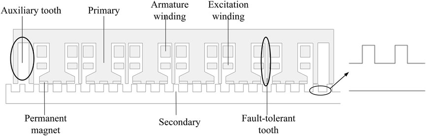
FIGURE 1. Topology of the motor.
Because the primary iron core of the primary permanent magnet linear motor is disconnected, the motor has edge effect, which is also the main reason for the motor thrust fluctuation. In order to reduce the thrust fluctuation by changing the structure, auxiliary teeth with two teeth structure are added at both ends of the primary. This is one of the predominant means to reduce the thrust fluctuation of permanent magnet linear motor.
Figure 2 shows the working state of the DC excitation winding of the motor. It can be seen that when the excitation winding plays the role of increasing flux, the permanent magnetic field has the same direction as the electric excitation field, and the magnetic field of the mixed excitation field is greatly enhanced compared with the pure permanent magnet field. This will inevitably increase the satiety of the primary iron core. However, due to the existence of fault-tolerant teeth, the magnetic flux will pass through the secondary to form a path along the fault-tolerant teeth, which will avoid passing through adjacent pole shoes. When the excitation winding is on the action of flux weakening, the direction of permanent magnetic field is opposite to that of electric excitation magnetic field. The two magnetic fields are in parallel, so they belong to parallel hybrid excitation. Compared with series excitation, the electric excitation magnetic path does not pass through the permanent magnet, so the magnetic resistance is small, and the risk of irreversible demagnetization of the permanent magnet is greatly reduced. This is also one of the advantages of alternating pole arrangement of permanent magnets.
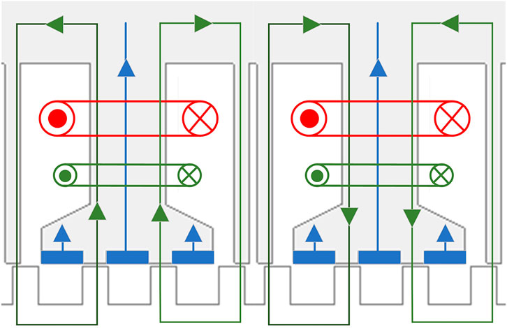
FIGURE 2. Flux-enhancing and flux-weakening condition.
In order to arrange the magnetic field distribution, improve the magnetic flux path, and further improve the no-load back EMF waveform, the secondary is added with a double-layer magnetic barrier. Because the addition of the magnetic barrier will not affect the armature winding current and other parameters of the motor, when optimizing the secondary structure, ordinary secondary can be used instead, only adding the magnetic barrier in the final result. The topology is shown in Figure 3.
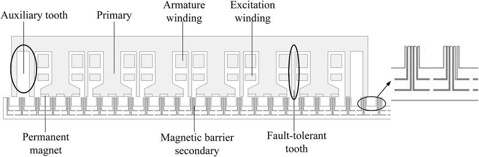
FIGURE 3. Topology of magnetic barrier motor.
Figure 4 shows the distribution of no-load magnetic field lines and magnetic density clouds of two structures of the motor in three typical states of weakened field, no electric excitation and increased field. It can be clearly seen that the saturation degree of the primary iron core in the two states of increasing and weakening magnetism is very different from that in the case of no electric excitation. This is a necessary and sufficient condition for thrust regulation and also meets the basic requirement of hybrid excitation motor. The auxiliary tooth can effectively retain part of the magnetic flux, rather than leaking through the end. Thus, the thrust fluctuation caused by the end effect is reduced.
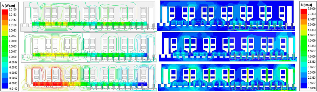
FIGURE 4. Open-circuit flux line distributions under different excitation levels.
3 Operating principle and electromagnetic analysis of the motor
3.1 Operating mechanism
The operating principle of hybrid excitation primary permanent magnet linear motor is similar to that of traditional primary permanent magnet linear motor, which also needs to meet the following requirements:
where
The running speed of the motor and the frequency of the sinusoidal current in the AC armature winding meet:
where
Using the mathematical model of primary permanent magnet linear motor for reference, regardless of the saturation of motor core, end effect and higher harmonics, it can be considered that the current flowing into the armature winding is three-phase sinusoidal alternating current. With the constant phase amplitude coordinate transformation, the flux linkage equation in dq coordinate system can be expressed as:
where
According to the flux linkage equation, the electromagnetic force equation can be obtained as follows:
The electromagnetic thrust of hybrid excitation permanent magnet linear motor contains two components. The first component is the magnetic resistance caused by the saliency effect of the magnetic pole. However, the difference with the primary permanent magnet linear motor lies in the second component. The second component is composed of permanent magnet and DC excitation force, so it is verified from the equation that for the hybrid excitation primary permanent magnet linear motor, the amplitude of electromagnetic thrust can be easily monitored by adjusting the DC excitation current.
3.2 Analysis of the motor’s electromagnetic performance
With the movement of the secondary, the variable reluctance effect of salient iron core makes the magnetic linkage of the turn chain in each coil of the armature winding change alternately. The advantage of the magnetic barrier secondary is to optimize the magnetic flux path along the regular path, thereby optimizing the back EMF, thrust, etc., which makes them more smooth. Figure 5 shows the comparison of no-load back EMF of ordinary secondary and magnetic barrier secondary. The back EMF of both structures is generally positive linear. The reason why the back EMF is irregular is that the structure is not optimized.
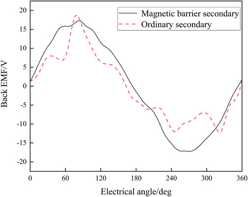
FIGURE 5. Comparison of back EMF.
Figure 6 shows the FFT factoring of the air gap flux density when the permanent magnet and the excitation winding act separately. It can be seen from the figure that the number of poles of the main magnetic field generated by the permanent magnet acting alone is 18, and its main working harmonic is the fundamental harmonic. The number of pole pairs of the main magnetic field produced by the excitation winding acting alone is 6, its third harmonic is 18, and the main working harmonic is the third harmonic. After the modulation of 20 teeth of the secondary, the two main magnetic fields produce two pairs of pole magnetic density. The frequency of back EMF induced by permanent magnet and excitation winding in armature winding is the same and there is no phase difference. Therefore, the final total back EMF generated in the armature winding is the scalar sum or scalar difference of the back EMF induced in the armature winding by the permanent magnet and the excitation winding acting separately.
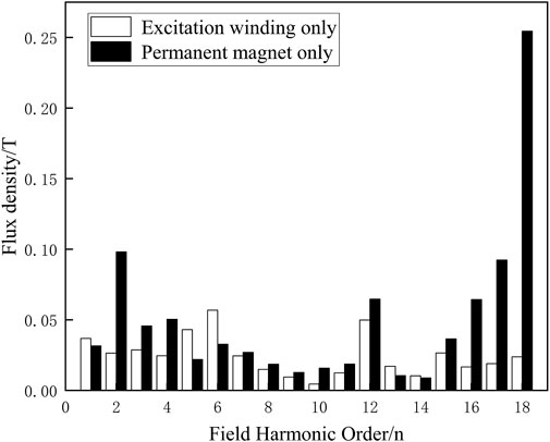
FIGURE 6. FFT factoring of the air gap flux density.
4 Structural optimization and loading analysis
4.1 Optimization of motor structure
According to the magnetic field modulation principle which mainly refers to magnetic gear effect (Cheng et al., 2021), the secondary, salient pole, of the primary permanent magnet linear motor acts as a modulator, and by using the alternating change of magnetic conductance, the salient reluctance modulates the distribution of any source magnetomotive force applied to the air gap. The pole arc coefficient of the secondary has a great influence on the thrust of the motor. Therefore, optimizing the pole arc coefficient of the secondary is an important means to optimize the motor performance. Figure 7 shows the thrust change of the motor when the pole arc coefficient is in the range of 0.2–0.7. With the increase of the pole arc coefficient, the thrust will first increase and then decrease, which is related to the degree of saturation of the secondary, thus affecting the strength of the magnetic field modulation, thereby affecting the level of the back EMF.
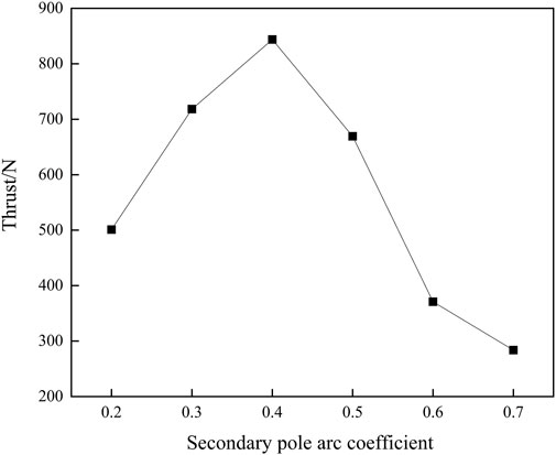
FIGURE 7. Effect of secondary pole arc coefficient on thrust.
Figure 8 is the diagram of the ferromagnetic pole shoe. The ferromagnetic pole shoes and the permanent magnets on both sides form the alternating pole structure, and they are the important part of the alternating pole structure. Pole shoe also provides a path for the magnetic flux generated by the excitation winding. The width of the pole shoe affects the electromagnetic performance of the motor, so it is necessary to optimize the pole arc coefficient of the primary teeth. The primary pole arc coefficient
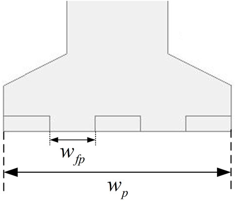
FIGURE 8. Primary ferromagnetic pole shoes.
Figure 9 shows the thrust change and thrust adjustment amplitude of the motor when the primary pole arc coefficient is within the range of 0.2–0.6. The thrust increases first and then decreases. When the pole arc coefficient is 0.4, the thrust reaches the maximum. It is because the saturation degree of the pole shoe decreases gradually, while the magnetomotive force of permanent magnet increases gradually, both of which are factors affecting the magnitude of main magnetic flux and thrust. The thrust adjustment amplitude also reaches the maximum with the coefficient of 0.4. After comprehensive consideration, the primary pole arc coefficient is determined as 0.4.
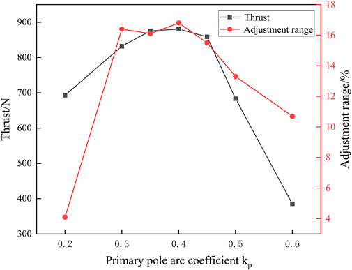
FIGURE 9. Influence of primary pole arc coefficient on thrust and regulating amplitude.
4.2 Loading analysis
Considering the structure optimization above, the effective value of sinusoidal current and current lead angle in armature winding may be unreasonable. A reasonable value is to be found. First, it is necessary to determine the current advance angle of the armature current, because after the structure is determined, the lead angle of the armature current has been unchangeable. The method is to roughly parameterize the scanning advance angle range and then positioning precisely. The current advance angle of both structures is—8deg. Figure 10 shows the relationship between the average thrust of the ordinary secondary and the armature current advance angle.
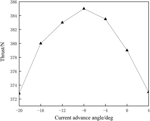
FIGURE 10. Influence of armature current advance angle on thrust.
The intensity of armature current directly affects the linear thrust of primary permanent magnet. Therefore, it is necessary to select the appropriate armature current as the rated current. The relationship between armature current and thrust of ordinary secondary is shown in Figure 11. With the increase of armature current, the thrust increases linearly. When the current exceeds 10A, the thrust increases slowly, indicating that the primary core is gradually saturated. Therefore, the rated current of this structure is determined to be 10A. It can be seen from this figure that when the current is the same, the thrust of the ordinary secondary structure is higher than that of the magnetic barrier structure. Therefore, the final secondary structure selected is the ordinary secondary.
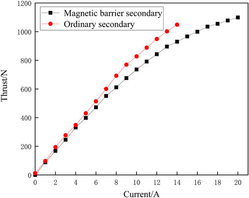
FIGURE 11. Influence of armature current on thrust.
Comparison before and after motor optimization are shown in Table 1.
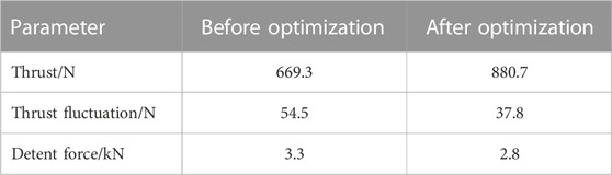
TABLE 1. Comparison before and after motor optimization.
Since rated current and current lead angle are determined, it is necessary to verify the thrust adjustment amplitude of the hybrid excitation primary permanent magnet linear motor. The current density of DC excitation winding should not be too large, and the common wire diameter is 3* 1.5. Therefore, the maximum value of DC excitation current density is 4
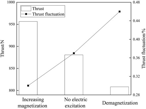
FIGURE 12. Average thrust and thrust fluctuation of the three states.
Main parameters of motor are shown in Table 2.
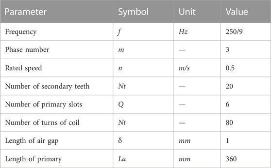
TABLE 2. The parameters of the motor.
5 Temperature field analysis
Temperature rise is a very important indicator of the motor. The motor is generally in a relatively closed space when working, so the heat generated will cause the temperature of each part to rise, not only showing a decline in electromagnetic performance, but also affecting its own operating reliability and service life. If the temperature rise exceeds the allowable working temperature, it may even cause motor winding burning, permanent magnet demagnetization and other consequences, resulting in irreversible losses. Compared with the traditional permanent magnet linear motor, the hybrid excitation permanent magnet linear motor has a set of DC excitation windings, additionally, so it is necessary to analyze the temperature field of the proposed hybrid excitation primary permanent magnet linear motor.
5.1 Basic principles of heat transfer
The heat transfer of main motor is mainly divided into three forms: heat conduction, heat convection and heat radiation. The heat conduction is based on the temperature difference. In addition to the temperature difference, the heat convection conditions include the fluidity of the object and the heating mode that can promote the material flow. The influence of thermal radiation is usually ignored when analyzing the thermal field of motor (Wang et al., 2021).
In the three-dimensional coordinate system, the heat transfer rate is:
where
The relation in the thermal convection is as follows:
5.2 Transient temperature field simulation of motor
In the state of increasing magnetization, the magnetic flux in the core of the motor hybrid excitation primary permanent magnet linear motor increases, resulting in the temperature of the core is higher than that in other states. Therefore, in the calculation of temperature field, it is only necessary to consider the temperature in the worst case, assuming that the ambient temperature of the motor is 22°C and the ambient temperature remains unchanged when the motor is running. The transient temperature of the motor in the state of magnetizing is simulated by using the finite element simulation software. The transient temperature at 7200 s is obtained. The sectional drawing of the motor is shown in Figure 13.
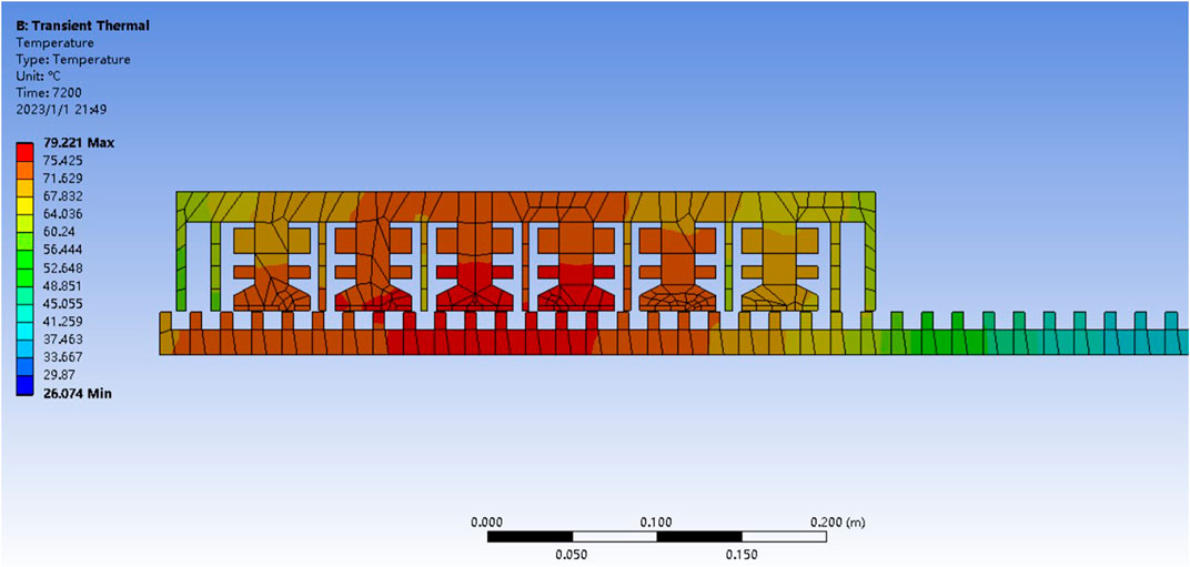
FIGURE 13. The temperature of sectional drawing of the motor.
The heat generation rate of the winding is much higher than that of the permanent magnet and core. The heat transferred to the surrounding air by heat convection is not much. Most of the heat is accumulated in the winding and transferred to the surrounding primary core by heat conduction. Therefore, the middle temperature of the motor is higher than the temperature of both sides.
Due to the irreversible demagnetization phenomenon caused by the high temperature of the permanent magnet material (Zhang et al., 2021), attention should be paid to the temperature of the permanent magnet. The heat generation characteristics of the motor cause that the temperature of the permanent magnet on the middle primary teeth in this structure will be higher than that on both sides. Figure 14 shows the temperature distribution cloud diagram of the permanent magnet on the horizontal section. It can be seen that the maximum temperature of the permanent magnet is not higher than 80°C, and the permanent magnet material used in this motor is Nd Fe35. It can be seen from its demagnetization curve that the permanent magnet in this structure will not undergo irreversible demagnetization.
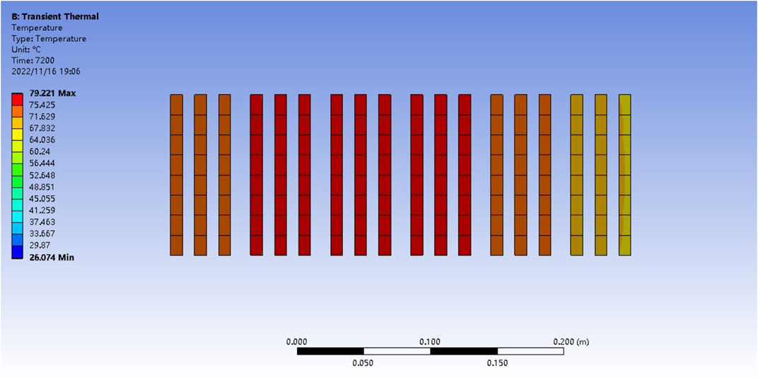
FIGURE 14. The temperature of the permanent magnet on the horizontal section.
6 Conclusion
In this paper, two hybrid excitation primary permanent magnet linear motors with different secondary structures are proposed. Through two-dimensional finite element analysis, the influence of no-load back EMF, primary pole arc coefficient, effective value of armature current and current lead angle on motor thrust of the two structures are compared. The temperature field of the finally determined ordinary secondary hybrid excitation primary permanent magnet linear motor on the state of magnetization is analyzed. The research results show that:
(1) Although the secondary back EMF waveform of the magnetic barrier secondary is better than that of the common reluctance secondary with the same pole arc coefficient, the magnetic barrier secondary is easier to saturate. After the optimization of various parameters of the motor, the pole arc coefficients of the primary and secondary are both 0.4, and the thrust of the common reluctance secondary is greater.
(2) When the motor is in the magnetizing state, the maximum transient temperature is lower than 80°C at 7200 s. Although the temperature is high, it is lower than the demagnetization temperature of the permanent magnet, ensuring the reliability of the motor operation.
(3) When adjusting the intensity and direction of the current of the electric excitation winding, Through the flexible control of increasing and weakening the magnetic field of the motor. It can meet the requirements of motor for constant power speed regulation and driving load with low speed and large thrust.
Data availability statement
The original contributions presented in the study are included in the article/supplementary material, further inquiries can be directed to the corresponding author.
Author contributions
All authors listed have made a substantial, direct, and intellectual contribution to the work and approved it for publication.
Funding
This work is supported in part by the National Natural Science Foundation of China under grant 51777127; Shenyang Science and Technology Plan Project 22-322-3-23; Liaoning Provincial Department of Education Scientific Research Project under grant LJKZ1085.
Conflict of interest
The authors declare that the research was conducted in the absence of any commercial or financial relationships that could be construed as a potential conflict of interest.
Publisher’s note
All claims expressed in this article are solely those of the authors and do not necessarily represent those of their affiliated organizations, or those of the publisher, the editors and the reviewers. Any product that may be evaluated in this article, or claim that may be made by its manufacturer, is not guaranteed or endorsed by the publisher.
References
Cheng, M., Wen, H., Hua, W., and Zhang, G. (2021). General airgap field modulation theory for electrical machines and its typical appl. Proc. CSEE 64 (024), 6063. doi:10.1109/TIE.2017.2682792
Cheng, Y., Zhao, W., Jinghua, J. I., Zhao, P., Yuxuan, D. U., et al. (2019). Unity power factor direct thrust force control of linear permanent-magnet vernier motor fed by dual inverter. Proc. CSEE 39 (07), 1870–1878. doi:10.13334/j.0258-8013.pcsee.181982
Du, K., Zhao, W., Xu, L., and Ji, J. (2020). Design of a new fault-tolerant linear permanent-magnet vernier machine. IEEE J. Emerg. Sel. Top. Industrial Electron. 1 (99), 172–181. doi:10.1109/jestie.2020.3020225
Gao, Y., Qu, R., Li, D., and Jian, L. (2016). “A novel hybrid excitation flux reversal machine for electric vehicle propulsion,” in 2016 IEEE Vehicle Power and Propulsion Conference, Hangzhou, China, 17-20 October 2016.
Jing, L., Huang, Z., Chen, J., and Qu, R. (2020). Design, analysis, and realization of a hybrid-excited magnetic gear during overload. IEEE Trans. Industry Appl. 56 (5), 4812–4819. Sept.-Oct. doi:10.1109/TIA.2020.3004425
Lv, G. (2020). Review of the application and key Technology in the linear motor for the rail transit. Proc. CSEE 40 (17), 5665–5675. doi:10.13334/j.0258-8013.pcsee.200488
Okada, T., Matsumori, H., Kosaka, T., and Matsui, N. (2019). Hybrid excitation flux switching motor with permanent magnet placed at middle of field coil slots and high filling factor windings. CES Trans. Electr. Mach. Syst. 3 (3), 248–258. doi:10.30941/cestems.2019.00033
Qasim, M., Khan, F., Ullah, B., Jan, H. U., and Islam, Z. U. (2021). “A novel double-sided linear flux switching machine with yokeless secondary for long stroke applications,” in 2021 International Conference on Emerging Power Technologies (ICEPT), Topi, Pakistan, 10-11 April 2021.
Shen, Y., and Lu, Q. (2021). Overview of permanent magnet linear machines with primary excitation. Trans. China Electrotech. Soc. 2021, 20867284. doi:10.1109/EVER52347.2021.9456610
Shen, Y., Lu, Q., Shi, T., and Xia, C. (2021). Analysis and evaluation of hybrid-excited doubly salient permanent magnet linear machine with dc-biased armature current. IEEE Trans. Industry Appl. 57 (57-4), 3666–3677. doi:10.1109/tia.2021.3079344
Ullah, B., Khan, F., Qasim, M., Jan, H. U., and Khalid, S. (2021). “Design and analysis of consequent Pole dual stator hybrid excited linear flux switching machine for rail transit system,” in 2021 International Conference on Emerging Power Technologies (ICEPT), Topi, Pakistan, 10-11 April 2021.
Wang, X., Li, G., and Qu, C. (2021). “Temperature field analysis of primary permanent magnet linear motor with magnetic barrier coupling,” in 2021 13th International Symposium on Linear Drives for Industry Applications (LDIA), Wuhan, China, 01-03 July 2021.
Wu, Z., Fan, Y., Chen, H., Wang, X., and Lee, C. H. T. (2021). Electromagnetic force and vibration study of dual-stator consequent-Pole hybrid excitation motor for electric vehicles. IEEE Trans. Veh. Technol. 70 (05), 4377–4388. doi:10.1109/tvt.2021.3075461
Zeng, Z., Lu, Q., and Ye, Y. (2017). A novel nine-phase modular hybrid-excited flux-switching linear machine. Proc. CSEE 37 (21), 6158–6167. doi:10.13334/j.0258-8013.pcsee.170534
Zhang, C., Li, B., Ye, P., and Zhang, H. (2021). Analog-Hall-Sensor-Based position detection method with temperature compensation for permanent-magnet linear motor. IEEE Trans. Instrum. Meas. 70, 1–11. Art no. 9512111. doi:10.1109/TIM.2021.3104378
Zhao, W., Du, K., and Xu, L. (2020). Design considerations of faultfault-tolerant permanent magnet vernier machine. IEEE Trans. Industrial Electron. 67 (9), 7290–7300. doi:10.1109/TIE.2019.2942571
Zhao, X., Niu, S., Zhang, X., and Fu, W. (2021). Flux-modulated relieving-DC-saturation hybrid reluctance machine with synthetic slot-PM excitation for electric vehicle in-wheel propulsion. IEEE Trans. Industrial Electron. 68 (07), 6075–6086. doi:10.1109/tie.2020.2996140
Keywords: hybrid excitation, fault-tolerant linear motor, thrust, temperature field analysis, primary permanent magnet linear motor
Citation: Wang X, Liu W, Qu C and Yang S (2023) Electromagnetic design and temperature field analysis of hybrid excitation primary permanent magnet linear motor. Front. Energy Res. 11:1104833. doi: 10.3389/fenrg.2023.1104833
Received: 22 November 2022; Accepted: 30 January 2023;
Published: 22 February 2023.
Edited by:
Enhua Wang, Beijing Institute of Technology, ChinaReviewed by:
Arturo García Pérez, University of Guanajuato, MexicoQinfen Lu, Zhejiang University, China
Copyright © 2023 Wang, Liu, Qu and Yang. This is an open-access article distributed under the terms of the Creative Commons Attribution License (CC BY). The use, distribution or reproduction in other forums is permitted, provided the original author(s) and the copyright owner(s) are credited and that the original publication in this journal is cited, in accordance with accepted academic practice. No use, distribution or reproduction is permitted which does not comply with these terms.
*Correspondence: Wanming Liu, MTU4MDI0MjIwMTVAMTYzLmNvbQ==