 Renzhi Huang
 Chen Dong1
- 1School of Electrical Engineering, Southeast University, Nanjing, China
- 2State Grid Jiangsu Electric Power Co., Ltd. Research Institute, Nanjing, China
- 3Nari Group Corporation (State Grid Electric Power Research Institute), Nanjing, China
Introduction: This paper proposes a sigmoid-based adaptive inertia control strategy for grid-forming (GFM) inverter to enhance frequency stability.
Methods: Firstly, the frequency response characteristics under different disturbances are analyzed theoretically. Then, to solve the problem that fixed inertia leads to a contradiction between the maximum frequency deviation and the setting time, a non-linear inertia regulator is investigated. This non-linear inertia regulator, which is based on an improved sigmoid function, is applied to achieve real-time inertia by the frequency deviation. Moreover, the full-order small-signal model of the system containing the nonlinear inertia regulator is established and thus the stability of the proposed strategy is analyzed.
Result and Discussion: The proposed control strategy is implemented without derivative action, which may suffer from high-frequency noises. Finally, the hardware-inthe-loop (HIL) results verify the remarkable performance of the proposed control strategy.
1 Introduction
As the integration of renewable energy sources increases, distributed generation systems with inverters as the interface are becoming increasingly important in the conventional grid (Pan et al., 2013; Xie et al., 2021). The massive use of power electronics and the withdrawal of synchronous machines have led to a lack of inertia in the power system, thus making the frequency stability of the system increasingly problematic (Blaabjerg et al.,2006; Li et al.,2018). To address this problem, a concept of GFM inverter generating distributed virtual inertia was proposed (Lasseter et al.,2019; Quan et al.,2019; Liu et al.,2016; Zhong and Weiss, 2010). The GFM inverter using virtual inertia control can effectively increase the inertia of the power system, reduce the frequency deviation and decrease the rate of change of the grid frequency under large disturbances (Fang et al., 2017). Hence, this paper focuses on the virtual inertia of the GFM inverter.
Virtual inertia control simulates the behavior of a real synchronous generator, but because control parameters such as inertia are virtual, this makes the design of its control parameters both flexible and complex. In order to meet the operational requirements of the system, the parameter design of the virtual inertia control was investigated (Dhingra and Singh., 2018). For example, a step-by-step parameters design method based on the line-frequency-averaged small-signal model of GFM inverter is proposed in (Wu et al.,2016). On the basis of the parallel small-signal model, the effect rules of the eigenvalues by droop coefficient, line parameters, GFM inverter’s parameters, and low pass filter parameters are examined and derived in (Zhang et al., 2017). The parameters of the proposed GFM inverter were optimized in (Shintai et al., 2014). However, these criteria strongly influence each other and it is difficult to balance multiple performance indicators. Therefore, attempts were made to improve the traditional virtual inertia control method in order to better control system. A modified virtual inertial strategy is used for the configuration of GFM inverter in (Shi et al., 2018; Xu et al., 2019), which helps the system to be closer to the theoretical analysis conditions of the traditional virtual inertial algorithm.
However, the GFM inverter also faces stability problems under grid disturbances while benefiting from the operation of simulated synchronous generators. In the event of large signal disturbances, such as transmission line faults, critical grid voltage droop and large load swings, the GFM inverter is exposed to stability risks. The transient behaviors of GFM inverter with power-synchronization control were examined in (Wu and Wang., 2018) under various grid fault scenarios. In (Xin et al., 2016; Huang et al., 2017), a fundamental droop-controlled GFM inverter transient instability phenomenon was discovered in the situation of a current saturation caused by the grid voltage sag. The power-angle curve was used to provide a qualitative examination of reactive power management in (Shuai et al.,2018), which shows how it degrades the GFM inverter’s transient stability. Although obvious, it does not precisely identify how and to what extent the transitory behavior is impacted by the reactive power control and other control elements. Due to the enormous complexity inherent in large-signal non-linear dynamic reactions, this is in fact a basic difficulty in the study of transient stability.
In addition to large disturbances, small disturbances are also an important research element in virtual inertia control (Li et al., 2004; Zhang et al., 2009; Zhang et al., 2010). However, existing studies show that fixed control parameters always lead to a contradiction between the overshoot and the setting time of the system (Chong et al., 2015). To solve this problem, it is necessary to adapt the values of the control parameters to the different scenarios and disturbances in real-time. An adaptive control method based on reinforcement learning and adaptive dynamic programming (ADP) is proposed in (Wang et al., 2021), but its stability was not verified. The GFM inverter-based adaptive damping control strategy in (Zheng et al., 2016) limits the frequency oscillations to a reliable range and attenuates the output power oscillations. However, the effect of virtual inertia on the system is not considered. In (Markovic et al., 2018), a linear quadratic regulator-based (LQR) optimization technique is used to adaptively adjust the emulated inertia and damping constants. However, only a pure simulation platform was used to verify the feasibility of the strategy and no hardware platform verification was performed. An adaptive control scheme combining virtual inertia control with an additional damping controller was proposed in the literature (Wang et al., 2022). This literature establishes a mathematical model of a wind power grid-forming system with a damping controller. However, only the response effect of the system output power was focused on and the frequency stability aspect was not investigated. All the literature above utilize damping adaption. In contrast, this paper focuses on adaptive adjustment of inertia.
In the control method of adaptive virtual inertia, scholars extensively adopted frequency differentiation as a standard of measurement. An adaptive virtual inertia control strategy based on an improved bang-bang control strategy for a micro-grid is presented in (Li M et al., 2019). On the one hand, it can make full use of the variability of virtual inertia to reduce dynamic frequency deviation. On the other hand, the steady-state interval of frequency and the steady-state inertia are set to improve the system frequency stability. Alternating inertia is also proposed in (Alipoor et al., 2014; Cheng et al., 2015; Li et al., 2016; Wang et al., 2018; Zhang et al., 2020), where the main idea is to give the moment of inertia by evaluating the state of the frequency deviation Δf and its rate of change df/dt. However, df/dt is very sensitive to high-frequency noise, which is inevitable in real physical systems. Therefore, the practical performance of this type of control is influenced by high-frequency noise. A communication-free adaptive virtual inertia control to realize the power oscillation suppression of cascaded-type virtual synchronous generators (VSGs) is proposed in (Li et al., 2023), where the adaptive inertia link contains dωDi/dt. But the measurement noises caused by direct calculation is avoided by deriving the formula with rounding roots so that dωDi/dt is obtained without derivative action. In (Li J et al., 2019), A dual-adaptivity inertia control strategy was proposed, but the system stability was not verified when the adaptive regulator was introduced. Moreover, the theoretical analysis of frequency response under power disturbance is not investigated. A practical control method without derivative action is proposed by (Hou et al.,2020). The control method proposed in this paper also does not have a derivative action. The proposed algorithm conquers this chattering deficit without frequency derivative action. It gives tremendous promise for engineering application backgrounds with high-frequency noise.
In this paper, a sigmoid-based adaptive inertia control strategy for GFM inverter is proposed to enhance frequency stability. The frequency response characteristics under different disturbances are theoretically analyzed at first. Then, a non-linear inertia regulator, which is based on an improved sigmoid function, is investigated to adjust the inertia by frequency deviation. Hence, the proposed strategy can achieve a better overall dynamic performance than the fixed inertia regulator. Besides, the full-order small-signal model of the system containing the non-linear inertia regulator is established in this paper to evaluate the stability of the proposed strategy. Compared with (Alipoor et al., 2014; Li et al., 2016; Wang et al., 2018; Zhang et al., 2020), the proposed adaptive strategy is implemented without derivative action (df/dt) and thus the performance is insensitive to high-frequency noise. Finally, the effectiveness of the proposed strategy is verified by the hardware-in-the-loop (HIL) results.
2 Control structure of GFM inverter
The control scheme of GFM inverter is shown in Figure 1. The main control structure includes an inner voltage and current control loop and an outer power control loop. In the voltage and current control loop, PI control is used to track the reference value. Hence, the control formula under the dq reference system can be obtained as Eq. 1.
where ud and uq represent the command voltage for modulating the converter, respectively; ic_refd and ic_refq are the control reference current, respectively; uod, uoq, iod and ioq are the inverter output voltage and current, respectively; icd and icq denote the inverter bridge arm current; ω is the angular frequency provided by the outer power control loop; Cf and Lf indicate filter capacitor and inductor, respectively; Kvp, Kvi, Kip and Kii are the PI control parameters, respectively.
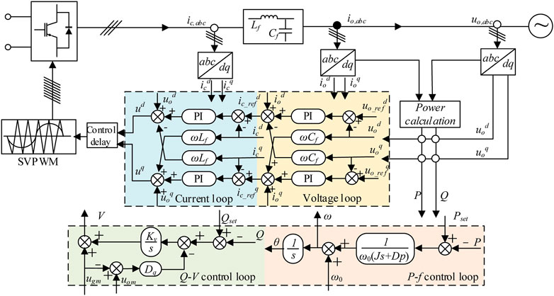
FIGURE 1. Control scheme diagram of GFM inverter.
In the P-f control loop, the function of GFM inverter to support the frequency stability is realized through virtual inertia, and the control equation is as follows:
where P and Pset represent the active power and its reference, respectively. ω and ω0 denote GFM inverter’s angular frequency and the nominal angular frequency, respectively. J and Dp are the virtual inertia and the damping ratio. Since the objective of this paper is to regulate inertia in P-f control loop, the Q-V control loop is neglected in this paper.
Digital control has an inherent control delay problem because sampling and calculation take a certain amount of time to complete, making it difficult to control the system in real-time. According to (Vukosavic et al.,2017; Wang et al.,2015), the various delays of the system are included in a delay link, which is placed before the PWM loop.
Assuming that there is a delay of one sampling period in the modulated wave update with respect to the sampling moment, the transfer function of the delay and the zero-order retainer in the continuous domain is:
where τ > 0 is the system sampling time. e−τs is an irrational function, which is not conducive to subsequent analysis. To evaluate the effect of delay on system stability, the second-order Pade approximation is utilized to simplify the analysis process.
Therefore the equation of state for the delayed link is:
where
3 Influence of virtual inertia on system frequency output
where
When the system is subject to a small disturbance, GFM inverter can be regarded as a linearized model near the operating point. At this point, the system can be considered a model with two inputs and a single output, as shown in Figure 2. Based on this, a simplified small-signal model of GFM inverter can be obtained, as shown in Eq. 6.
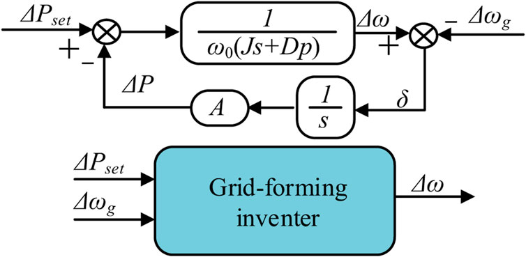
FIGURE 2. Equivalent input and output of the system under small disturbance.
3.1 Transfer function of the angular frequency
As the power response under various perturbations has been analyzed in detail in (Wang et al.,2021),. the study in this paper focuses on the frequency response, which will be discussed in detail in two perturbation cases.
1. When
2. When
When the step change of active power reference value, the transfer function in Eq. 7 may be utilized as an analytical tool. The transfer function in Eq. 8 can be used to investigate how the frequency swings when the short time disturbance of the grid frequency. According to Eq.7 and Eq.8, GFM inverter is a second-order system whose natural frequency ωn and damping ratio ζ can be expressed as follows:
Since the virtual damping coefficient
3.2 Influence of virtual inertia on the frequency response of GFM inverter
1) Step change of active power reference value: when the reference value of active power changes suddenly as Eq. 10, the deviation of active power output can be varied as Eq. 11.
where α represents the degree of change, u(t) is the unit step function.
The expression of peak time and corresponding angular frequency can be expressed as Eq.12 and Eq.13, respectively.
where β = arctan
Based on the transfer function in Eq. 11, Figure 3 illustrates the curve of Δω(t) as the virtual inertia grows from J1 to J5. An observation of the graph shows that the highest value of the curve decreases while the duration of the curve oscillation grows as J increases. It can be found that bigger J gives smaller overshoot, but longer peak time. Therefore, in the case of the step change of active power the variation of J has the opposite effect on the overshoot and peak time of inverter frequency.
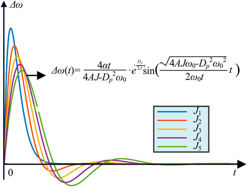
FIGURE 3. Frequency response under different virtual inertia values in the step change of active power reference value.
In contrast to (Li M et al., 2019), this paper gives a detailed derivation of equations and theoretical analysis of the frequency response under the step change of active power reference value, illustrating the effect of virtual inertia J on frequency in this case.
2) Short time disturbance of the grid frequency: the grid frequency will change described in Eq. 14 when the grid is disturbed. Meanwhile, the angular frequency deviation of inverter can be obtained from Eq. 15.
where τ indicates the duration of grid frequency.
In this case, the time when the frequency deviation reaches the peak value and the corresponding output are the same as the research method in the case of the step change of active power reference value, so it will not be repeated here. Figure 4 depicts the reaction curve of Δω(t) as the virtual inertia grows from J1 to J5, based on the transfer function in Eq. 11. From Figure 4, it is clear that with the increase of virtual inertia J, the overshoot becomes smaller, but the setting time becomes longer. Therefore, when the grid frequency disturbance for a short time, the change of J has the opposite effect on the overshoot and the setting time of inverter output frequency.
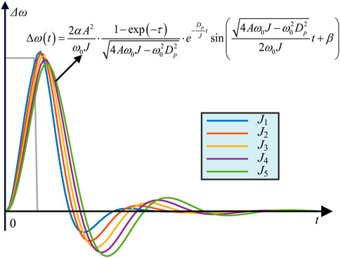
FIGURE 4. Frequency response under different virtual inertia values in the short time drop of the grid frequency.
In general, a larger virtual inertia will reduce the overshoot of the angular frequency in the above two cases. However, the setting time of the inverter frequency will become longer after the system is interfered if the virtual inertia J is too large. Therefore, it can be concluded that the change of the virtual inertia has opposite effects on the two indicators of the system output angular frequency dynamic performance: the overshoot and the setting time.
4 A sigmoid-based adaptive inertia regulator
From the analysis in Section 2, it is unrealistic to set a fixed virtual inertia J so that the inverter can meet the requirements of the small overshoot and the short setting time under various disturbances of different amplitude. Therefore, this paper proposes a sigmoid-based adaptive inertia regulator to adjust the virtual inertia. The basic strategy is as follows:
In order to improve the dynamic performance of inverter output frequency, the value of virtual inertia J should be adaptive: when the amplitude of frequency deviation is small, the inverter can ignore the impact of the overshoot and minimize the virtual inertia of the system to achieve rapid response and ensure the system recovery as soon as possible. Once the frequency deviation of the system becomes larger, it should mainly suppress the frequency oscillation and try to increase the virtual inertia of the system to reduce overshoot.
The virtual inertia generated by the sigmoid-based adaptive inertia regulator is shown in Eq. 16, and its function curve is shown in Figure 5.
where Jmin and Jmax are the lower limit and upper limit of virtual inertia, respectively. a and k denote the adjustment coefficients. Δf is the input of the sigmoid-based adaptive inertia regulator. By using different values of a and k, the shape of the regulation can be changed. In this paper, a is used to control the curve to move right or left. k is used to control the slope of the curve and can be expressed as the sensitivity of the tuning function. According to Eq. 16, J = (Jmin + Jmax)/2 when Δf = a. Hence, a is designed to |Δf|max/2 in this paper, where |Δf|max is the maximum frequency deviation of the power grid.
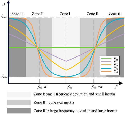
FIGURE 5. Sigmoid-based adaptive inertia regulation curve under different k.
In order to balance the overshoot and response speed, the range of system damping ratio ζ is generally required (Wu et al.,2016). According to the expression of ζ in Eq. 9, the upper limit Jmin and lower limit Jmax of Eq. 16 can be calculated.
Figure 5 shows the curves of sigmoid-based adaptive inertia regulation with different k. There are five curves in Figure 5, where k increases from Υ0 to Υ4 and Υ0 means k = 0. The inertia regulator can be divided into three Zones, which are Zone I with small frequency deviation and small inertia, Zone II with upheaval inertia and Zone III with large frequency deviation and large inertia. When the frequency deviation is small with ordinary state, the inertia regulator works in Zone I. Hence, the corresponding inertia is very small, which can respond to interference as soon as possible. When a disturbance occurs. The increase in frequency deviation causes the inertial regulator to enter Zone II further leading to a rapid growth in virtual inertia. Then, the inertia regulator is transferred to Zone III to maintain a large inertia with the further increase of frequency deviation. Finally, the inertia regulator is returned to work in Zone I with the decrease of the frequency deviation.
5 Stability analysis
The inertia regulator designed in Section 3 is a non-linear part, and its introduction will inevitably affect the system. In order to analyze the influence of the control strategy in this paper on the stability of the system, a full-order small-signal model of GFM inverter containing the inertia regulator is established in this section and thus the eigenvalue analysis is provided to guide the selection of control parameters.
5.1 Full-order small-signal model
The general form of the linearized small-signal state-space model of the system is (
where Δ represents small disturbance, xsys denotes the state variable of the system and Asys is the state matrix of the system.
where Δφd, Δφq, Δγd and Δγq are the state variables introduced by voltage outer loop and current inner loop, respectively; Δicd, Δicq, Δiod, Δioq, Δuod and Δuoq are the minor change of icd, icq, iod, ioq, uod and uoq, respectively. Δxd1, Δxd2, Δxd3 and Δxd4 q are the minor change of xd1, xd2, xd3 and xd4 in Eq. 5, respectively.
5.2 Root-locus analysis
The parameters of GFM inverter are listed in Table 1. Based on the full-order small-signal model in Eq. 18, the stability of the sigmoid-based inertia strategy is analyzed by using the trajectory of the dominant eigenvalues with k varying from 0.1 to 1000, as illustrated in Figure 6. The trajectory of the dominant eigenvalues with τ varying can be plotted as in Figure 7.
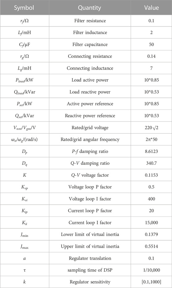
TABLE 1. Parameters of GFM inverter.
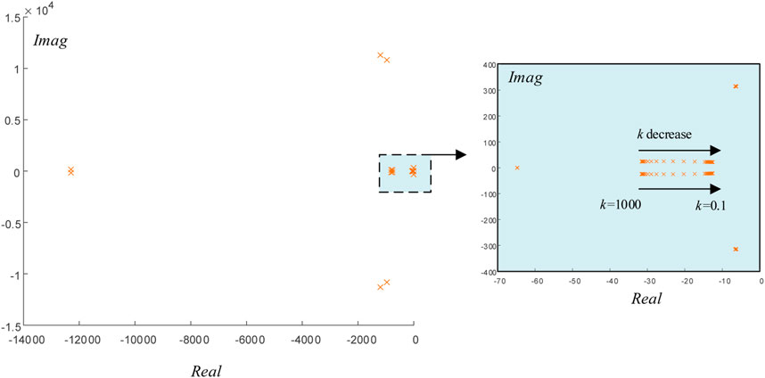
FIGURE 6. The trajectory of the dominant eigenvalues with k varying.
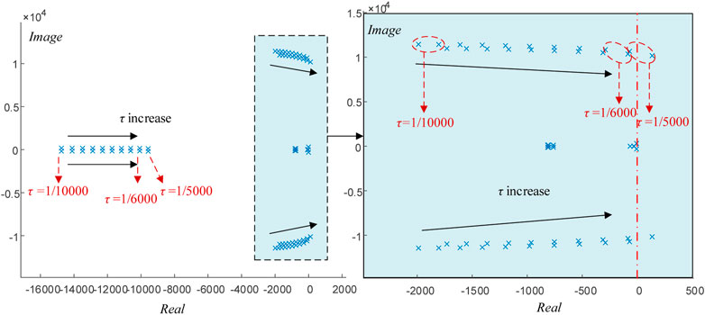
FIGURE 7. The trajectory of the dominant eigenvalues with τ varying.
Figure 6 shows that when k is decreased, the dominant eigenvalues moves to the right, indicating that the stability degrades. However, the eigenvalues of the system are all located on the left side of the real axis, which indicates that the system is stable after adding the sigmoid-based adaptive inertia regulator.
Figure 7 shows that the increased of τ causes the stability degrades. The eigenvalues of the system are all located on the left side of the real axis when τ increased from 1/10,000 to 1/6000. However, some of the eigenvalues lie to the right of the real axis when τ = 1/5000, which means that the system become unstable.
In summary, the system becomes unstable after the delay time increases to τ = 1/5000. Therefore, in some high-power situations with low switching frequency, a control delay compensation algorithm should be added to ensure the stability of the system (Pan et al.,2013).
6 Case studies
To fully verify the effectiveness of the proposed strategy, a hardware-in-the-loop (HIL) platform is established. As shown in Figure 8, the HIL platform consists of four parts: an OPAL RT-LAB OP5700 real-time digital simulator, three Ti’s TMS320FDSP28377D digital signal processor (DSP)-based control boards, a personal computer (PC) and a Tektronix MOS54 oscilloscope. Firstly, the PC downloads the C-based program to the DSP through the emulator. The RT-LAB is connected to PC via RJ45 Cable. Then, the control commands are sent down from the RT-LAB to the DSP. The DSP implements the control algorithm and generates the modulation signal to the RTLAB. The data transfer between DSP and RTLAB is realized through I/O interface card. Finally, the test results are displayed in oscilloscope which is connected to RT-LAB by the I/O interface card.
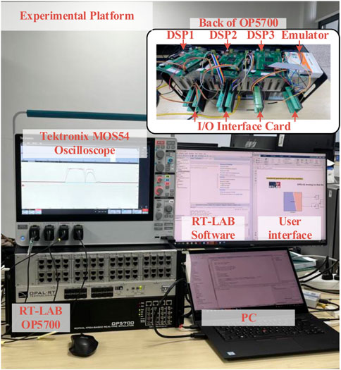
FIGURE 8. Hardware in loop experimental platform.
6.1 Verification of system stability
To verify the stability of the proposed strategy, k = 0.1, 40 and 200 are compared in this scenario. The disturbances are set as follows: Pset is suddenly increased to 17 kW and suddenly decreased to 8.5 kW after 2 s. Besides, the frequency oscillation begins after 4 s and lasts 0.2 s. The HIL test results are shown in Figure 9.
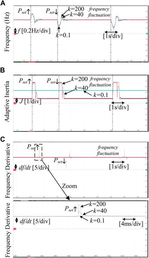
FIGURE 9. The proposed strategy with different K (A) Frequency of GFM inverter. (B) Adaptive inertia of GFM inverter. (C) Frequency derivative of GFM inverter.
Specifically, Figure 9 shows that the system is stable under disturbances, which verifies the stability of the proposed strategy. Meanwhile, the smaller k (k = 0.1) means that the proposed strategy cannot adjust the inertia according to frequency deviation. The larger k (k = 200) makes the adaptive inertia regulator sensitive to frequency deviation and thus the sigmoid-based adaptive inertia regulator has fast inertia adjustment capability. However, the larger value of k will also cause a sharp increase in the rate of change of frequency (RoCoF), which can cause tremendous damage to the generator of grid, as displayed in Figure 9C. Therefore, a proper k = 40 is designed to balance the adaptive ability of inertia regulator and RoCoF of system.
6.2 Dynamic performance of the proposed strategy
The conventional strategy II with small constant inertia (J = 0.05), the conventional strategy III with big constant inertia (J = 3), the strategy IV with bang-bang inertia control in (Alipoor et al.,2014), the strategy V (Hou et al.,2020) and the proposed sigmoid-based inertia strategy I are compared in the following scenarios to validate the dynamic performance. In (Alipoor et al.,2014), two kinds of inertia values are determined by evaluating the states of frequency deviation Δf and the rate of its change (df/dt).
Remark1: Each of the aforementioned strategies is implemented independently in the DSP-based control boards. The disturbances, such as sudden changes in active power and frequency fluctuation, are generated in RT-LAB.
Remark 2: The output powers and its references of strategy I, strategy II, strategy III and strategy IV are represented by P1, P2, P3 and P4, respectively. The power references of strategy I, strategy II, strategy III and strategy IV are denoted by Pset1, Pset2, Pset3 and Pset4.
Scenario 1: A sudden active power command is given to GFM inverter. The initial Pset1 = Pset2 = Pset3 = 8.5 kW. In this scenario, the disturbances are set as follows: All of the Pset are stepped up to 17 kW and then Pset is set returned to 8.5 kW after 2 s. The HIL test results are shown in Figure 10.
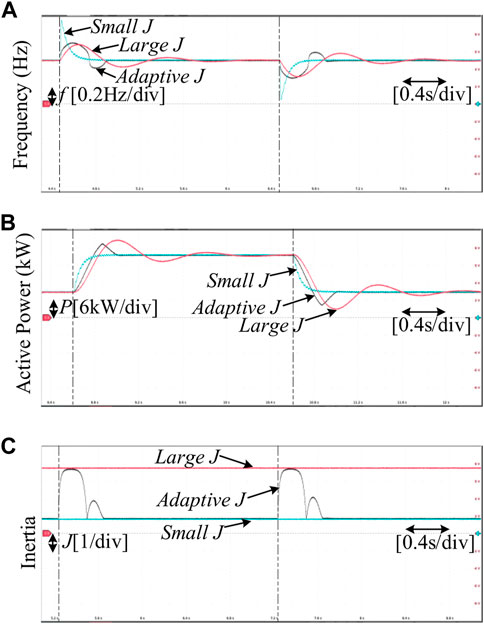
FIGURE 10. Experimental results of Scenario 1. (A) Frequency of GFM inverter. (B) Active power of GFM inverter. (C) Inertia of GFM inverter.
Scenario 2: A sudden fluctuation in the angular frequency of the common coupling point. The initial Pset are same as Scenario 1. The disturbances are set as follows: the frequency oscillation begins after 2 s and lasts 0.2 s. The HIL test results are displayed in Figure 11.
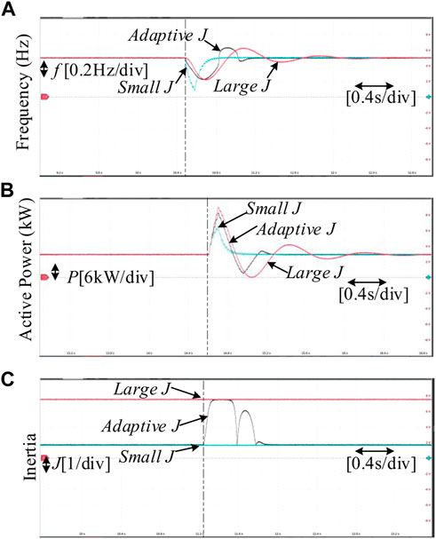
FIGURE 11. Experimental results of Scenario 2. (A) Frequency of GFM inverter. (B) Active power of GFM inverter. (C) Inertia of GFM inverter.
Figure 10 shows that the trend of the active power and frequency is similar for the three control strategies. The active power follows the references and the frequency is restored to stability after disturbances. However, their dynamic performances are different. The setting time of strategy II is short due to the small inertia while a large frequency deviation also accompanies it. The large frequency deviation threatens the frequency stability of the system. On the contrary, strategy III has a longer setting time although the maximum frequency deviation is smaller. Hence, Fixed inertia control strategies, such as strategies II and III, always lead to a contradiction between the maximum frequency deviation and the setting time of the system. Fortunately, the maximum frequency deviation of the proposed strategy I is similar to strategy III and is only 2/3 of strategy II. The adjustment time of the proposed strategy I is also significantly shorter than that of strategy III. For the setting time, the proposed strategy I longer than strategy II but significantly shorter than strategy III. Therefore, the proposed strategy I achieves better overall dynamic performance.
Figure 11 also illustrates the good dynamic performance of the proposed strategy I when frequency fluctuations occur. Their specific analysis is similar to the previous one. Hence, it is omitted in this paper.
6.3 Comparison with existing method
Scenario 3: Similar to Scenario 1, a sudden active power command is given to GFM inverter. The initial Pset1 = Pset4 = 8.5 kW. Both of the Pset are stepped up to 17 kW. Moreover, a high-frequency noises are imposed into the frequency of GFM inverter. To illustrate the difference between the proposed strategy I in this paper and strategy IV in (Alipoor et al.,2014), Scenario 3 is used. The HIL test results of Scenario 3 are shown in Figure 12.
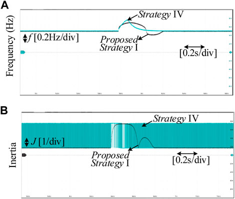
FIGURE 12. Experimental results of Scenario 3. (A) Frequency of GFM inverter. (B) Inertia of GFM inverter.
As observed, although strategy IV converges quickly, the frequency deviation is larger than the proposed strategy I. This phenomenon is mostly caused by the sensitivity of alternating inertia to high-frequency noises. Due to the erroneous interference of df/dt, the alternating inertia cannot always maintain a large value during the disturbance process, as shown in Figure 12B. In fact, when strategy IV is implemented, a first-order low-pass filter has been added to the differential operation. However, the erroneous interference of df/dt still exists in HIL experiments. It indicates that the sensitivity of alternating inertia to high-frequency noises cannot solve by the first-order low-pass filter. In general, the adaptive control proposed in this paper is not affected by high-frequency noise due to the absence of differential operation. Therefore, the proposed strategy I is more advantageous and valuable in practical use compared to strategy IV.
Scenario 4: Similar to Scenario 1, a sudden active power command is given to GFM inverter. The initial Pset1 = Pset4 = 8.5 kW. Both of the Pset are stepped up to 21.25 kW. The sudden active power command in this Scenarioexceedes the set value, which is 1.5 times larger than in Scenario 3. Scenario 4 helps to analyze the impact of strategy on system uncertainty.
To illustrate the difference between the proposed strategy I in this paper and strategy V in (Hou et al.,2020), Scenarios 1 and 4 are used. The HIL test results of Scenarios 1 and 4 are shown in Figure 13.
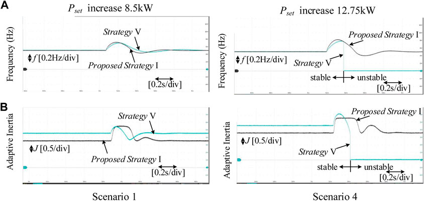
FIGURE 13. Experimental results of Scenarios 1 and 4. (A) Frequency of GFM inverter. (B) Inertia of GFM inverter.
As observed, both strategies can adjust the inertia to achieve good dynamic performance in Scenario 1. The maximum frequency deviation of strategy V is slightly lower than that of strategy I, while the setting time of strategy I is slightly shorter. When the frequency deviation is small, the adaptive inertia of strategy I is smaller, that’s why setting time of strategy I is slightly shorter. In general, both strategies show good dynamic performance without significant differences.
However, when there is uncertainty in the system, i.e., the power command is out of the preset range. As shown in Figure 13 Scenario 4, the inertia in strategy V is out of the safety range, resulting in system instability. This indicates that the control parameters of strategy V need to be carefully designed and retain some margin. Otherwise there is a risk of system instability when the sudden active power command exceeds a predetermined value (Hou et al.,2020). From the principle of the proposed strategy I, the inertia is strictly limited to the safety range. Hence, the system can still maintain stability in Scenario 4.
Based on the above experiments, Table 2 can be listed. It is clear that the proposed strategy in this paper achieves a small frequency deviation of the same magnitude as a large inertia strategy. And the setting time is also shortened. Compared to the bang-bang control, the proposed strategy reduces frequency deviation and avoids the problem of high-frequency noise. Compared to strategy V, the proposed strategy shows better robustness to the uncertainty of the system.
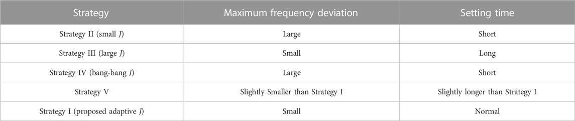
TABLE 2. Comparison of dynamic response under different strategies.
7 Conclusion
In this paper, the frequency response under the disturbances of active power and frequency are theoretically analyzed. Then, the problem that the fixed inertia leads to a contradiction between the maximum frequency deviation and the setting time is presented. Hence, this paper proposed a sigmoid-based inertia control strategy to solve the problem. The stability of proposed strategy is verified by establishing the full-order small-signal model of GFM inverter containing the inertia regulator. By using the proposed control strategy, the system inertia can be varied by frequency deviation to achieve a good dynamic performance on both maximum frequency deviation and setting time. Moreover, the proposed strategy shows strong robustness with high-frequency noises in system frequency due to the absence of derivative action. The effectiveness of the proposed control strategy is verified through HIL results.
Due to the sensitivity of differencing to high-frequency noise, researchers who want to study further in this field should avoid directly employing frequency differentiation for adaptive regulation in the future. One method is to eliminate the operations of frequency differentiation by mathematical method, such as (Hou et al.,2020). Another method is to directly design a virtual inertia regulator without differentiation.
Data availability statement
The raw data supporting the conclusion of this article will be made available by the authors, without undue reservation.
Author contributions
RH, writing-original draft, writing-review, theoretical analysis and simulation research. CD, writing-original draft, theoretical analysis and simulation research. ZW, conceptualization. All authors participated in the writing and editing of manuscript.
Funding
This work was supported by State Grid Corporation of China under Grant 5419-202140235A-0-0-00.
Conflict of interest
Author TS was employed by State Grid Jiangsu Electric Power Co., Ltd. Author KH was employed by Nari Group Corporation.
The remaining authors declare that the research was conducted in the absence of any commercial or financial relationships that could be construed as a potential conflict of interest.
The authors declare that this study received funding from State Grid Corporation of China. The funder had the following involvement in the study: the writing and editing of this article.
The handling editor PL declared a shared affiliation with author HY at the time of the review.
Publisher’s note
All claims expressed in this article are solely those of the authors and do not necessarily represent those of their affiliated organizations, or those of the publisher, the editors and the reviewers. Any product that may be evaluated in this article, or claim that may be made by its manufacturer, is not guaranteed or endorsed by the publisher.
References
Alipoor, J., Miura, Y., and Ise, T. (2014). Power system stabilization using virtual synchronous generator with alternating moment of inertia. IEEE J. Emerg. Sel. Top. Power Electron. 3 (2), 451–458. doi:10.1109/jestpe.2014.2362530
Blaabjerg, F., Teodorescu, R., Liserre, M., and Timbus, A. V. (2006). Overview of control and grid synchronization for distributed power generation systems. IEEE Trans. Industrial Electron. 53 (5), 1398–1409. doi:10.1109/tie.2006.881997
Cheng, C., Yang, H., Zeng, Z., Tang, S. Q., and Zhao, R. X. (2015). Rotor inertia adaptive control method of VSG. Automation Electr. Power Syst. 39 (19), 82–89.
Chong, C., Huan, Y., Zheng, Z., Shengqing, T. A. N. G., and Rongxiang, Z. H. A. O. (2015). Adaptive control method of rotor inertia for virtual synchronous generator. Automation Electr. Power Syst. 19, 82–89.
Dhingra, K., and Singh, M. (2018). Frequency support in a micro-grid using virtual synchronous generator based charging station. IET Renew. Power Gener. 12 (9), 1034–1044. doi:10.1049/iet-rpg.2017.0713
Fang, J., Li, H., Tang, Y., and Blaabjerg, F. (2017). Distributed power system virtual inertia implemented by grid-connected power converters. IEEE Trans. Power Electron. 33 (10), 8488–8499. doi:10.1109/tpel.2017.2785218
Hou, X., Sun, Y., Zhang, X., Lu, J., Wang, P., and Guerrero, J. M. (2020). Improvement of frequency regulation in VSG-based AC microgrid via adaptive virtual inertia. IEEE Trans. Power Electron. 35 (2), 1589–1602. doi:10.1109/tpel.2019.2923734
Huang, L., Xin, H., Wang, Z., Zhang, L., Wu, K., and Hu, J. (2017). Transient stability analysis and control design of droop-controlled voltage source converters considering current limitation. IEEE Trans. Smart Grid 10 (1), 578–591. doi:10.1109/tsg.2017.2749259
Lasseter, R. H., Chen, Z., and Pattabiraman, D. (2019). Grid-forming inverters: A critical asset for the power grid. IEEE J. Emerg. Sel. Top. Power Electron. 8 (2), 925–935. doi:10.1109/jestpe.2019.2959271
Li, D., Zhu, Q., Lin, S., and Bian, X. Y. (2016). A self-adaptive inertia and damping combination control of VSG to support frequency stability. IEEE Trans. Energy Convers. 32 (1), 397–398. doi:10.1109/tec.2016.2623982
Li, J., Wen, B., and Wang, H. (2019). Adaptive virtual inertia control strategy of VSG for micro-grid based on improved bang-bang control strategy. IEEE Access 7, 39509–39514. doi:10.1109/access.2019.2904943
Li, L., Sun, Y., Liu, Y., Tian, P., and Shen, S. (2023). A communication-free adaptive virtual inertia control of cascaded-type VSGs for power oscillation suppression. Int. J. Electr. Power & Energy Syst. 149, 109034. doi:10.1016/j.ijepes.2023.109034
Li, M., Huang, W., Tai, N., Yang, L., Duan, D., and Ma, Z. (2019). A dual-adaptivity inertia control strategy for virtual synchronous generator. IEEE Trans. Power Syst. 35 (1), 594–604. doi:10.1109/tpwrs.2019.2935325
Li, M., Huang, W., Tai, N., and Yu, M. (2018). Lyapunov-based large signal stability assessment for VSG controlled inverter-interfaced distributed generators. Energies 11 (9), 2273. doi:10.3390/en11092273
Li, Y., Vilathgamuwa, D. M., and Loh, P. C. (2004). Design, analysis, and real-time testing of a controller for multibus microgrid system. IEEE Trans. Power Electron. 19 (5), 1195–1204. doi:10.1109/tpel.2004.833456
Liu, J., Miura, Y., Bevrani, H., and Ise, T. (2016). Enhanced virtual synchronous generator control for parallel inverters in microgrids. IEEE Trans. Smart Grid 8 (5), 2268–2277. doi:10.1109/tsg.2016.2521405
Markovic, U., Chu, Z., Aristidou, P., and Hug, G. (2018). LQR-based adaptive virtual synchronous machine for power systems with high inverter penetration. IEEE Trans. Sustain. Energy 10 (3), 1501–1512. doi:10.1109/tste.2018.2887147
Pan, D., Ruan, X., Bao, C., Li, W., and Wang, X. (2013). Capacitor-current-feedback active damping with reduced computation delay for improving robustness of LCL-type grid-connected inverter. IEEE Trans. Power Electron. 29 (7), 3414–3427. doi:10.1109/tpel.2013.2279206
Quan, X., Huang, A. Q., and Yu, H. (2019). A novel order reduced synchronous power control for grid-forming inverters. IEEE Trans. Industrial Electron. 67 (12), 10989–10995. doi:10.1109/tie.2019.2959485
Shi, K., Ye, H., Song, W., and Zhou, G. (2018). Virtual inertia control strategy in microgrid based on virtual synchronous generator technology. IEEE Access 6, 27949–27957. doi:10.1109/access.2018.2839737
Shintai, T., Miura, Y., and Ise, T. (2014). Oscillation damping of a distributed generator using a virtual synchronous generator. IEEE Trans. Power Deliv. 29 (2), 668–676. doi:10.1109/tpwrd.2013.2281359
Shuai, Z., Shen, C., Liu, X., Li, Z., and Shen, Z. J. (2018). Transient angle stability of virtual synchronous generators using Lyapunov’s direct method. IEEE Trans. Smart Grid 10 (4), 4648–4661. doi:10.1109/tsg.2018.2866122
Vukosavic, S. N., Peric, L. S., and Levi, E. (2017). Digital current controller with error-free feedback acquisition and active resistance. IEEE Trans. Industrial Electron. 65 (3), 1980–1990. doi:10.1109/tie.2017.2745476
Wang, F., Zhang, L., Feng, X., and Guo, H. (2018). An adaptive control strategy for virtual synchronous generator. IEEE Trans. Industry Appl. 54 (5), 5124–5133. doi:10.1109/tia.2018.2859384
Wang, J., Yan, J. D., Jiang, L., and Zou, J. (2015). Delay-dependent stability of single-loop controlled grid-connected inverters with <italic>LCL</italic> filters. IEEE Trans. Power Electron. 31 (1), 743–757. doi:10.1109/tpel.2015.2401612
Wang, T., Jin, M., Li, Y., Wang, J., Wang, Z., and Huang, S. (2022). Adaptive damping control scheme for wind grid-connected power systems with virtual inertia control. IEEE Trans. Power Syst. 37 (5), 3902–3912. doi:10.1109/tpwrs.2021.3140086
Wang, Z., Yu, Y., Gao, W., Davari, M., and Deng, C. (2021). Adaptive, optimal, virtual synchronous generator control of three-phase grid-connected inverters under different grid conditions—an adaptive dynamic programming approach. IEEE Trans. Industrial Inf. 18 (11), 7388–7399. doi:10.1109/tii.2021.3138893
Wu, H., Ruan, X., Yang, D., Chen, X., Zhao, W., Lv, Z., et al. (2016). Small-signal modeling and parameters design for virtual synchronous generators. IEEE Trans. Industrial Electron. 63 (7), 4292–4303. doi:10.1109/tie.2016.2543181
Wu, H., and Wang, X. (2018). Design-oriented transient stability analysis of grid-connected converters with power synchronization control. IEEE Trans. Industrial Electron. 66 (8), 6473–6482. doi:10.1109/tie.2018.2875669
Xie, X., Quan, X., Wu, Z., Cao, X., Dou, X., and Hu, Q. (2021). Adaptive master-slave control strategy for medium voltage DC distribution systems based on a novel nonlinear droop controller. IEEE Trans. Smart Grid 12 (6), 4765–4777. doi:10.1109/tsg.2021.3104413
Xin, H., Huang, L., Zhang, L., Wang, Z., and Hu, J. (2016). Synchronous instability mechanism of Pf droop-controlled voltage source converter caused by current saturation. IEEE Trans. Power Syst. 31 (6), 5206–5207. doi:10.1109/tpwrs.2016.2521325
Xu, H., Yu, C., Liu, C., Wang, Q., and Zhang, X. (2019). An improved virtual inertia algorithm of virtual synchronous generator. J. Mod. Power Syst. Clean Energy 8 (2), 377–386. doi:10.35833/mpce.2018.000472
Zhang, B., Yan, X., and Altahir, S. Y. (2017). “Control design and small-signal modeling of multi-parallel virtual synchronous generators,” in 2017 11th IEEE International Conference on Compatibility, Power Electronics and Power Engineering (Cadiz: CPE-POWERENG), 471–476.
Zhang, L., Harnefors, L., and Nee, H. P. (2010). Interconnection of two very weak AC systems by VSC-HVDC links using power-synchronization control. IEEE Trans. Power Syst. 26 (1), 344–355. doi:10.1109/tpwrs.2010.2047875
Zhang, L., Harnefors, L., and Nee, H. P. (2009). Power-synchronization control of grid-connected voltage-source converters. IEEE Trans. Power Syst. 25 (2), 809–820. doi:10.1109/tpwrs.2009.2032231
Zhang, L., Xie, Z., Chang, Y., and Zhu, H. (2020). “Virtual inertia adaptive control strategy for DFIG wind turbines based on exponential function,” in 2020 15th IEEE Conference on Industrial Electronics and Applications (Kristiansand: ICIEA), 407–411.
Zheng, T., Chen, L., Wang, R., Li, C. L., and Mei, S. (2016). “Adaptive damping control strategy of virtual synchronous generator for frequency oscillation suppression,” in 12th IET International Conference on AC and DC Power Transmission, 1–5.
Keywords: grid-forming (GFM) inverter, adaptive inertia control, small-signal model, frequency stability, sigmoid function
Citation: Huang R, Dong C, Wu Z, Quan X, Wang Z, Sun T and Hou K (2023) A sigmoid-based adaptive inertia control strategy for grid-forming inverter to enhance frequency stability. Front. Energy Res. 11:1095610. doi: 10.3389/fenrg.2023.1095610
Received: 11 November 2022; Accepted: 04 April 2023;
Published: 14 April 2023.
Edited by:
Pengfeng Lin, Nanyang Technological University, SingaporeReviewed by:
Liansong Xiong, Xi’an Jiaotong University, ChinaHaoxin Yang, Nanyang Technological University, Singapore
Xiaoyu Wang, Xi’an Jiaotong University, China
Cesar Angeles-Camacho, National Autonomous University of Mexico, Mexico
Copyright © 2023 Huang, Dong, Wu, Quan, Wang, Sun and Hou. This is an open-access article distributed under the terms of the Creative Commons Attribution License (CC BY). The use, distribution or reproduction in other forums is permitted, provided the original author(s) and the copyright owner(s) are credited and that the original publication in this journal is cited, in accordance with accepted academic practice. No use, distribution or reproduction is permitted which does not comply with these terms.
*Correspondence: Zaijun Wu, emp3dUBzZXUuZWR1LmNu