 Zixi Fang
 Renxin Yang1
- 1Key Laboratory of Control of Power Transmission and Conversion, Shanghai Jiao Tong University, Shanghai, China
- 2Xuji Electric Co., Ltd., Xuchang, China
The diode rectifier (DR) based hybrid dc converter can significantly increase the economy of the offshore wind power transmission system comparing with the traditional modular multilevel converter (MMC). However, the start-up and shut-down methods of this hybrid dc converter are not studied. In this paper, the start-up and shut-down strategies of the hybrid dc converter are proposed. The start-up process can be divided into two stages: uncontrollable precharging stage and controllable precharging stage. In the uncontrollable precharging stage, the calculation method of the precharging current is given and the design method of the current limiting resistor is presented. In the controllable precharging stage, a circulating current control strategy is proposed to balance the inner energy of the converter and charge the submodule capacitors to the rated value. Besides, the corresponding shut-down strategy is also introduced. Simulation results based on MATLAB/Simulink and hardware-in-the-loop experiment results based on the RT-LAB are provided to support the proposed strategies. The proposed start-up and shut-down strategies can charge and discharge the submodules of the hybrid DC converter safely and cheaply.
1 Introduction
Modular multilevel converter (MMC) has the advantages of high voltage level, high efficiency and low harmonics, which is one of the most competitive converter topology in the high voltage dc (HVDC) transmission (Nami et al., 2015; Lyu et al., 2019). However, the large number of the submodules make the MMC converter station huge and bulky, which would greatly increase the construction cost of the offshore platform and decrease the economy of the offshore transmission system. With the reduction of the wind power tariff, the economy of HVDC system is more and more important and becomes one of the restriction of the offshore wind power development (Yang et al., 2022).
In order to reduce the construction cost of the offshore converter station, the diode rectifier (DR) is attracting more and more attention due to the advantages of low cost, small volume and weight (Blasco-Gimenez et al., 2010)- (Cardiel-Álvarez et al., 2018). Nevertheless, there are some challenges when using the DR as the offshore sending converter (Bidadfar et al., 2021; Nami et al., 2020): 1) The black-start ability. The DR cannot transmit the active power in the opposite direction, which makes it unable to provide the necessary energy for offshore wind turbines (WTs) to achieve the black-start. 2) The synchronization method. The DR cannot establish the offshore grid voltages for the WTs to lock the phase, which makes it hard to realize the synchronization of the offshore WTs. 3) Harmonics and reactive power compensation. The additional ac filters would be needed to compensate the reactive power and harmonics in the system. In order to solve these problems, two technical routes are proposed and studied in these years. One is to make the WTs able to achieve black-start and form the offshore grid by themselves. Ramachandran studies the conventional black-start methods for the offshore WTs (Ramachandran et al., 2019). In the other technical route, a small capacity voltage source converter (VSC) is used to operate in parallel with the DR to make up these drawbacks in some references (Nguyen et al., 2014)- (Fang et al., 2022). Chang and Cai, (2019) proposes a hybrid DC converter, which can greatly increase the economy while meeting the requests of the offshore wind power transmission system. Based on this structure, Fang et al. (2022) improves the topology and control of this converter and fixes some drawbacks. However, the start-up and shut-down strategies of this topology are not studied, which is essential for the normal operation of this hybrid dc converter.
For the conventional MMC, several methods have been proposed to charge or discharge the submodule capacitors in the literatures (Das et al., 2011)- (Abu-Ali and Colak, 2022). An additional resistance is inserted in the MMC arms to precharge and discharge the submodule capacitors (Das et al., 2011). Shi et al. (2015) derives the small signal model of the capacitor charging loop and designed a feedforward control to improve the dynamic response and voltage control precision during the precharging process. Xu et al. (2021) proposed a smooth start-up strategy to charge the MMC consisting of full-bridge submodules and half-bridge submodules. Usually, the centralized discharging resistor is used to accelerate the discharging process of the submodules capacitors. However, by sequentially controlling the arm currents of the MMC to the arm resistors, the submodule capacitors can also be discharged without additional devices (Pan et al., 2018; Abu-Ali and Colak, 2022). In order to reduce the cost or achieve the dc fault ride-through ability, various submodule circuits are proposed and applied to the MMC. The corresponding startup strategies for those different types of submodules are also studied in recent researches (Zeng et al., 2015)- (Zhang et al., 2017). Zeng et al. (2015) studies the precharging strategy of the half-bridge and full-bridge submodules mixed hybrid MMC. The three-level flying capacitor submodules based MMC is also investigated (Dekka et al., 2017). Wang et al. (2019) and Xue et al. (2014) propose the startup methods of single-clamp and clamp-double submodules based MMC. Besides, a low voltage dc source can also be used to charge various submodules based MMC (Tian et al., 2016) and a generalized precharging strategy without additional circuits is proposed by Zhang et al. (2017) for MMC-HVDC system. Zhang et al. (2016) introduces the shut-down control for the MMC-HVDC system, in which the stored energy is dissipating through the HVDC line.
Besides the studies about charging and discharging strategies of the MMC, many references also study the startup sequence of offshore wind farms (OWFs) with HVDC grid connected system (Karaagac et al., 2017)- (Li et al., 2020). Karaagac et al. (2017) investigated and examined the startup sequence of point to point MMC-HVDC system for OWFs. For the multi-terminal MMC-based HVDC system with OWFs, the hierarchical startup control and overall sequential scheme are proposed by Wang et al. (2016). Jain, (2021) proposed a soft-start method for HVDC-connected large offshore wind power plants with grid-forming wind turbines (Anubhav et al., 2021). The DR-based hybrid HVDC system integrated with OWFs are receiving more and more attention. Yu et al. (2022) investigates the black-start method of the DR and MMC series-connected hybrid dc converter. The startup strategy for DR and MMC paralleled hybrid HVDC system is also studied by Li et al. (2020).
To address the precharging and discharging challenges of DR-based hybrid HVDC transmission system, the start-up and shut-down strategies are proposed in this paper. The start-up process is divided into two stages: the uncontrollable precharging stage and controllable precharging stage. For the uncontrollable precharging stage, the calculating method of the precharging current is introduced. Based on it, the precharging resistor is designed to limit the inrush current. For the controllable precharging stage, a circulating current control strategy is proposed to charge the submodules capacitors to the rated value. Besides, the corresponding shutdown strategy of the hybrid dc converter is also introduced, which can discharge the submodule capacitors quickly and safely. Finally, the validity of the proposed strategies is verified by both the simulation and hardware-in-the-loop experiment results.
This paper is organized as follows: Section 2 introduces the system structure and operation sequence of hybrid HVDC transmission system. Section 3 proposes the start-up strategy of the hybrid DC converter. In Section 4, the corresponding shut-down strategy of this converter is proposed. The simulation and experiment verifications are presented in Section 5, 6 respectively. Section 7 draws the conclusions for this paper.
2 Structure and operation sequence of hybrid HVDC transmission system
2.1 System structure
The system structure of the hybrid HVDC system is shown in Figure 1. The offshore wind farms are connected to the offshore ac grid and a 12-pulse diode rectifier is used to transmit energy from the offshore ac grid to the HVDC transmission line. The power rating of the diode rectifier is equal to the capacity of the OWFs. For the conventional WTs, the ac grid voltages should be provided to realize the synchronization and the energy is needed for the black-start in the initial condition. However, the diode rectifier could not form the offshore grid voltages and transmit the active power in the opposite direction. Besides, harmonics and reactive power would be generated by the diode rectifier and should be compensated. Therefore, an auxiliary converter is applied to address these issues, which is connected in parallel with the diode rectifier at ac and dc sides.
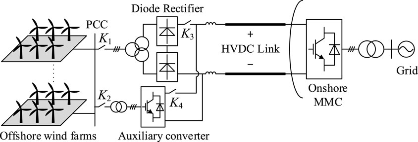
FIGURE 1. Structure of hybrid HVDC system.
In order to make up the drawbacks of the diode rectifier, the auxiliary converter must be fully controllable and able to transmit the active power bidirectionally. Because the auxiliary converter needs to provide the black-start energy for OWFs, the active power capacity of the auxiliary converter is about 2%–5% of the rated value of the system. In the steady-states, all the reactive power and harmonics should be compensated by the auxiliary converter. So the reactive power requirement is about 30%–40% of the rated value of the system. Chang and Cai, (2019) and Fang et al. (2022) proposed a high-ratio VSC to serve as the auxiliary converter in the hybrid HVDC system. The topology is shown in Figure 2A. This is also a new type of the modular multilevel converter, which can transmit the active power bidirectionally. The submodule branches (SMBs) withstand most of the HVDC voltage. Therefore, the dc voltage of the ac output unit (ACOU) is low and the submodules of the topology can be greatly reduced comparing with the traditional MMC. The operation principle and the parameter design methods of the hybrid converter have been fully introduced by Fang et al. (2022).

FIGURE 2. Topology of auxiliary converter. (A) Main circuit. (B) Half-bridge submodule.
The SMBs and ACOU are all constructed by the half-bridge submodules, which are shown in Figure 2B. The self-power supply is used to supply the sub-control system and driver, which is directly acquired from the inner capacitor of the submodule. Therefore, only when the capacitor voltage is beyond a certain value, the half-bridge submodule is controllable. Before the auxiliary converter operates in the normal condition, the capacitor voltages of the submodules must be at the rated value, which makes the precharging process of the converter essential.
However, Figure 2A shows that this topology is asymmetrical, which is different from the traditional MMC. The conventional start-up and shut-down strategies cannot be used in this topology. SMBs would be firstly charged than ACOU and the energy imbalance would also exist. Therefore, the unique start-up and shut-down strategies and design methods should be proposed for this auxiliary converter.
2.2 Operation sequence of the hybrid HVDC system
For the hybrid HVDC system, the operation sequence is shown as follows.
1) Start-up process: Firstly, the onshore MMC should complete the precharging process and establish the HVDC voltage. Before the start-up process of the offshore hybrid converter begins, the HVDC link can be regarded as a dc source. Then turn on the switch K4 and complete the precharging process of the auxiliary converter. After the auxiliary converter fully starts, turn on the switch K2 and establish the offshore grid voltages. So the OWFs could realize the synchronization and achieve black-start. The voltage establishing and black-start processes have been explained fully in the past references, which are ignored in this paper.
2) Normal operation: When the OWFs begin to generate active power, turn on the switch K1 and K3. Raise the offshore grid voltages to shift the active power from the auxiliary converter to the diode rectifier. The SMBs can be blocked after the power shift. The system operates in the normal condition.
3) Shut-down process: The shut-down process discussed in this paper refers to the normal condition, which does not include the emergence stop such as the fault protection. Firstly, all the WTs should be shut down and disconnected. Then turn off the switch K1, K2 and K3. The auxiliary converter begins the shut-down process. After that, turn off the switch K4 so the offshore system is completely stopped. Then the onshore MMC can also begin to be shut down according to the condition.
In the hybrid HVDC converter, the auxiliary converter is the mainly energy storage and controllable element. Therefore, the key point of this system is on the startup and shutdown strategies of the auxiliary converter.
As for the auxiliary converter, the operation sequence is shown in Figure 3. The operation sequence is similar with the traditional MMC. It could also be divided into three parts.
1) Start-up process: After the HVDC voltage is established, turn on the switch K4 so the converter begins the uncontrollable precharging stage. The capacitor voltages of the submodules could not reach the rated value during this process. However, the capacitor voltages can meet the demands of the self-power supply so the auxiliary converter is controllable. Then during the controllable precharging stage, all the capacitor voltages of the submodules can be fully charged.
2) Normal condition: the auxiliary converter is used to establish the offshore grid voltages and achieve the power shift, which is descripted in the operation principle of the hybrid HVDC system.
3) Shut-down process: The shut-down process of the auxiliary converter can be divided into three parts. Part 1 is the energy feedback stage. During this stage, the auxiliary converter actively reduces the capacitor voltages by feeding the energy back to the grid from the HVDC link. Part 2 is the controllable energy dissipation stage. The capacitors of the tuned filter and submodules can be discharged by the energy dissipation resistor Rd2. Nevertheless, the voltages of the submodules could not be fully discharged by the resistor Rd2. After the voltages is below Ublk, the self-power supply is disenabling and the submodules are blocked automatically. Part 3 is the uncontrollable energy dissipation stage. The remaining voltage is discharged by the inner resistor R0 in the submodule.
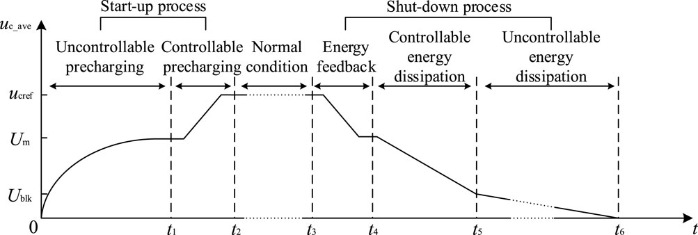
FIGURE 3. Operation sequence of auxiliary converter.
Although the operation process the auxiliary converter is similar with the traditional MMC, major differences exist in the specific implementation of each process between these two converters. Because of the asymmetry of auxiliary converter, the calculation method of the current-limiting resistor and the control strategies in the controllable precharging stage must be redesigned.
3 Start-up strategy of hybrid DC converter
3.1 Uncontrollable precharging stage
In the initial state, the switch K5 is turned off, which means the current-limiting resistor Rd1 is inserted to restrict the inrush current. Figure 4 shows the schematic diagram in the uncontrollable precharging stage. After the switch K4 is turned on, the capacitors of the tuned filter and the submodules are all charged from the HVDC link. According to Figure 4, the equivalent circuits of the auxiliary converter in the uncontrollable precharging stage are shown in Figure 5.
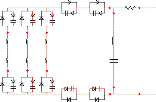
FIGURE 4. Schematic diagram in uncontrollable precharging stage.
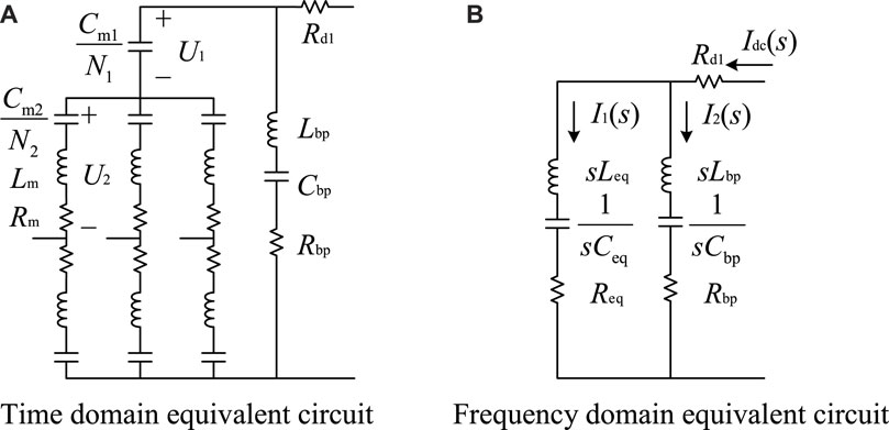
FIGURE 5. Equivalent circuits in uncontrollable precharging stage. (A) Time domain equivalent circuit. (B) Frequency domain equivalent circuit.
Because SMBs are series connected, they can be represented by a capacitor of which the capacitance is Cm1/N1. Cm1 is the capacitance of the submodule capacitor used in SMBs. N1 is the number of the submodules in SMBs. Also the arms of ACOU can be represented by the capacitors of which the capacitance is Cm2/N2. Cm2 is the capacitance of the submodule capacitor used in ACOU. N2 is the number of the submodules in the arm of ACOU. Therefore, the time domain equivalent circuit is shown in Figure 5A. Lm and Rm are the inductance and inner resistance of the arm inductor. Cbp is the tuned filter capacitor. Lbp and Rbp are the inductance and inner resistance of the tuned filter inductor.
The relationships between the capacitor voltages and dc voltages are shown as
Where Um1 and Um2 are the capacitor voltages of the submodules used in SMBs and ACOU, U1 and U2 are the dc voltages of SMBs and ACOU. According to Figure 5A, U1 and U2 satisfy the following equation:
From Eqs 1, 2, the expressions of the voltages are
Therefore, the relationship between the voltages of submodule capacitors in SMBs and ACOU after the uncontrollable precharging stage is expressed as
Usually for the modular characteristic, the submodules used in the converter are the same type, which makes Um1 three times of Um2. Therefore, huge energy imbalance would exist in the auxiliary converter between SMBs and ACOU after the uncontrollable precharging stage, which is different to the conventional MMC.
3.2 Calculation method of the current-limiting resistor
The value of the current-limiting resistor Rd1 would affect the peak value of the inrush current in uncontrollable precharging process. Therefore, the calculation method should be acquired to choose the proper value of this resistor. From Figure 5A, the frequency domain equivalent circuit can be acquired as shown in Figure 5B, where the equivalent value of the capacitor Ceq, the inductor Leq and the resistor Req are expressed as
Hence, the precharging currents can be further derived as
The expressions of the parameters in Eq. 6 are
It is hard to derive the time domain expression of the precharge current directly from Eq. 6. Therefore, the parameters of the system should be firstly acquired. Put theses parameters into Eqs 6–8, the frequency domain expression of the precharge current can be acquired. Also the time domain expression can be derived by the inverse Laplace-transformation. Hence, the relationship between the peak current and the current-limiting resistor can be gained.
Taking the parameters shown in Table 1 as the example, the relationship between the precharging current peak and the resistor Rd1 is shown in Figure 6. Assuming that Iset1 and Iset2 are the inrush current limit of the tuned filter and the submodules, when Iset1 is 600 A and Iset2 is 800A, the resistor Rd1 is selected as 108 Ω according to Figure 6.
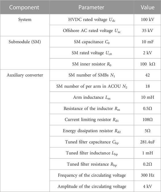
TABLE 1. Parameters of the simulation system.
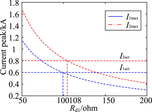
FIGURE 6. Relationship between precharge resistance and current peak.
After the current-limiting resistor is selected, the precharging current can be calculated and plotted according to Eqs 6–8. Besides, the corresponding simulation model is established in the Simulink. The calculation and simulation results of the precharging current are shown in Figure 7. From Figure 7 it can be seen that the calculation and simulation results are nearly the same, which verify the validity of the above analysis.
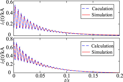
FIGURE 7. Comparison of the precharging current between calculation and simulation.
3.3 Controllable precharging stage
As mentioned before, the uncontrollable precharging process can only partly charge the submodule capacitors with huge energy imbalance between SMBs and ACOU. Therefore, the energy imbalance should be eliminated and the submodule capacitors should be charged to the rated value in the controllable precharging stage. Since the capacitor voltages have reached the demand value of the self-power supply after the uncontrollable precharge, the submodules become controllable.
For the auxiliary converter has the ability to generate the inner circulating voltages and current to balance the energy between SMBs and ACOU under normal condition, this operation principle can also be used during the controllable precharge stage, which is shown in Figure 8.
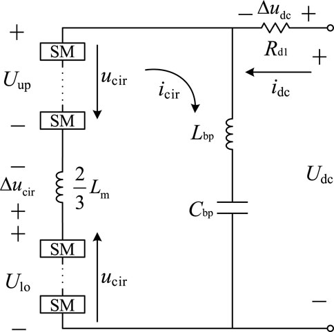
FIGURE 8. Controllable precharging schematic based on circulating current control.
In Figure 8, the ACOU is equivalent by an inductor and an arm of submodules. Besides the dc voltages supported by the SMBs and ACOU, the circulating voltage ucir is also generated in SMBs and ACOU. The circulating current control voltage Δucir is applied in SMBs to generate the circulating current icir. Figure 8 shows that the directions of the vectors of the circulating voltages in SMBs and ACOU are the opposite and the directions of icir and ucir are on the same line. Hence, icir would generate the opposite active power in SMBs and ACOU. Ignoring the losses, the absolute value of the active power generated in SMBs and ACOU are the same and the energy is transformed between these two parts. By the circulating voltages and current, the energy balance could be achieved in the auxiliary converter. In order to charge submodule capacitors to the rated value, the dc current idc of the auxiliary converter is controlled by the voltage Δudc to increase the energy stored in the converter. Hence, the voltages in SMBs Uup and ACOU Ulo are expressed as
The control strategy of the auxiliary converter in the controllable precharging stage is shown in Figure 9. When the uncontrollable precharging stage is over, all the submodules are inserted. Firstly, the steady circulating voltages are generated in SMBs and ACOU. The amplitude of ucir is gradually increased to the reference value. During this process, the submodules would be slightly charged and reach a new steady value. Taking this time as ts1, the circulating current control module is applied to balance the capacitor voltages between the submodules in SMBs and ACOU. After the uncontrollable precharging process, the capacitor voltages in SMBs are 3 times of in ACOU and the dc voltages supported by SMBs and ACOU are Udc1 and Udc-Udc1 respectively. This is determined by the characteristics of the topology. However, after the energy is balanced, the submodule capacitor voltages in the auxiliary converter are all the same. In this time, the dc voltages supported by the SMBs and ACOU should be according to the number of the submodules connected in series. Assuming that the dc voltages supported by SMBs and ACOU are Udc2 and Udc-Udc2 respectively after the energy is balanced, the dc voltage components are expressed as
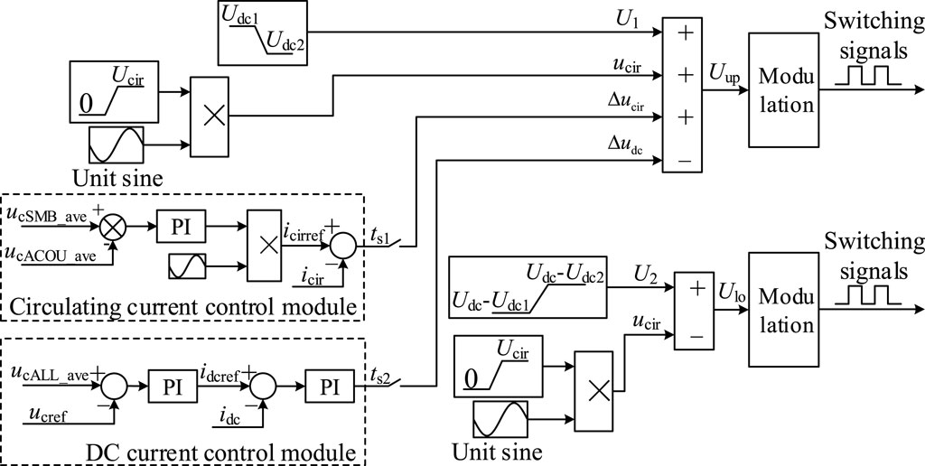
FIGURE 9. Control block diagram of the controllable precharging stage.
Taking this time as ts2, the dc current control module is applied to charge the submodule voltages to the rated value furtherly. During this process, the circulating current control module is still used to maintain the energy balance. After all the submodules are fully charged, the start-up process of the auxiliary converter is finished and the control strategy can be switched to establish the offshore grid voltages.
4 Shut-down strategy of hybrid DC converter
4.1 Energy feedback stage
In the energy feedback stage, the auxiliary converter tries to feed the storage energy in the submodules back to the HVDC link as much as possible. This stage can be regarded as the mirroring process of the controllable precharging stage. The control strategy shown in Figure 9 can also be used. The reference value ucref is changed so the auxiliary converter discharge to the HVDC link. For the HVDC voltage is still supported by the converter, the capacitors cannot be fully discharged in this stage. The minimum value of the capacitor voltage is calculated as
4.2 Energy dissipation Stage
After the energy feedback process, turn off the switch K4 to disconnect the auxiliary converter from the HVDC link. Then turn off the switch K5 and turn on the switch K6 so that the tuned filter capacitor is discharged through the resistor Rd1 and Rd2, which is shown in Figure 10A. During this process, all the submodules are blocked. For the resistor Rd1 is designed for the uncontrollable precharging process, the discharging current of the tuned filter capacitor can be guaranteed below the limited value.
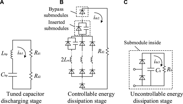
FIGURE 10. Energy dissipation stage. (A) Tuned capacitor discharging stage. (B) Controllable energy dissipation stage. (C) Uncontrollable energy dissipation stage.
After this capacitor is fully discharged, turn on the switch K5 and insert the submodules group by group. For only several submodules are inserted to discharge every time, the voltage and power level of the energy dissipation resistor Rd2 can be a low value. As mentioned before, the submodule would be blocked automatically if the capacitor voltage is below a certain value. Therefore, the submodule capacitors cannot be fully discharged during this stage. The remaining voltage is discharged through the inner resistor R0 of the submodule as shown in Figure 10C, which is defined as the uncontrollable energy dissipation stage. Due to the large resistance of the inner resistor of the submodule, the discharging time in this stage is much more longer than other stages.
5 Simulation results
5.1 Simulation environment
The simulation model is built in the Matlab/Simulink based on the parameters shown in Table 1. The system structure is shown in Figures 1, 2. In order to accelerate the simulating speed, the onshore MMC converter is replaced by a DC source. In the initial states, the capacitor voltages of the submodules are zero. Switches K1- K6 are turned off.
5.2 Simulation verification of the start-up process
Figure 11 shows the simulation results of the start-up process. At 0s, the switch K4 is turned on hence the uncontrolled precharging stage S1 is started. It can be seen that the submodule capacitors are charged preliminary from Figure 11A. The capacitor voltage of SMBs is three times of the ACOU, which is consistent with the theoretical analysis. From Figure 11B, the tuned filter capacitor is fully charged in this stage. At 0.5 s, the circulating voltages generating stage begins, which is S2. In this stage, ucir are formed in SMBs and ACOU gradually for the energy balancing process. The capacitors would be slightly charged. At 0.8 s, the circulating current control module is applied and energy balancing stage S3 begins. It can be seen that the submodule voltages of SMBs and ACOU are gradually approached. Eventually at 2 s, the capacitor voltages become the same. Then the dc current control module is applied at dc voltage charging stage S4. During this stage, the capacitor voltages of SMBs will reach the rated value firstly. Then through the energy balancing control, ACOU can be gradually charged. All the submodule capacitor voltages in the auxiliary converter will reach the rated value at 3 s and the precharging process is finished.
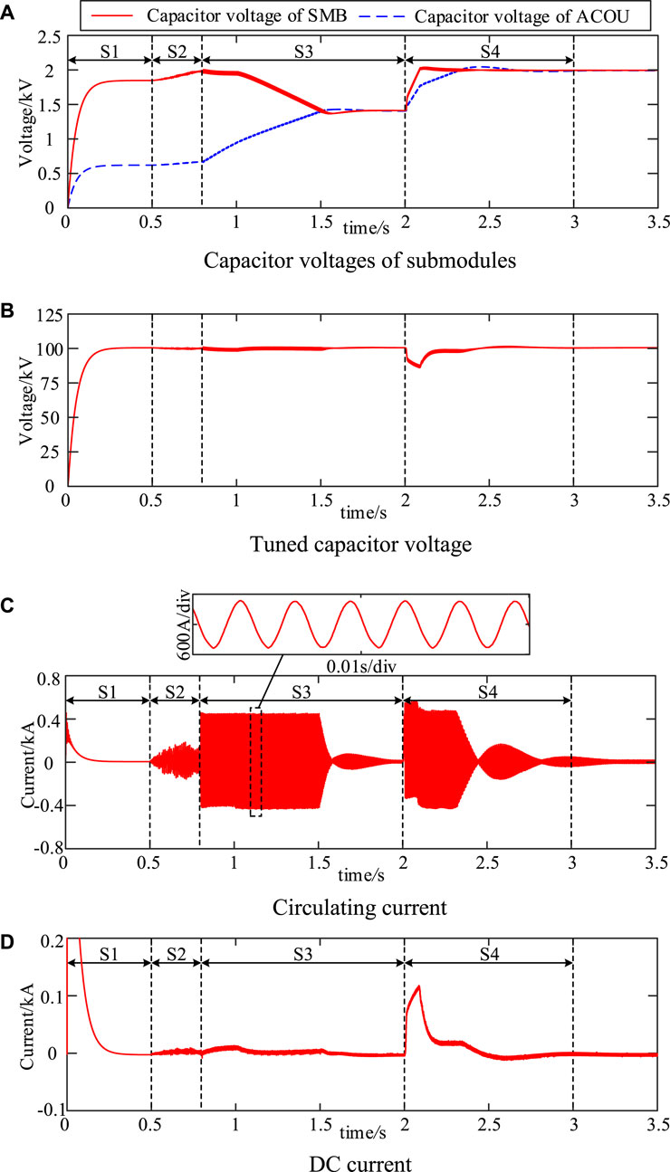
FIGURE 11. Simulation results during the start-up process. (A) Capacitor voltages of submodules. (B) Tuned capacitor voltage. (C) Circulating current. (D) DC current.
Figure 11C shows the circulating current during the start-up process. The simulation results in S1 are mainly shown in Figure 7. Figures 11C,D shows the simulation results of S2, S3, and S4. It can be seen that the circulating current is generated in S3 and S4 to balance the voltages of the submodules. The frequency of the circulating current is 300 Hz and the amplitude is limited to 500 A. Only when the capacitor voltages in SMBs and ACOU are different, the circulating current is generated. Figure 11D shows the dc current during the start-up process. In S3, the energy is flowing inside the auxiliary converter. So there is no dc current. In S4, the auxiliary converter charges from the dc side so that the dc current is instantly increased and the submodules are fully charged.
5.3 Simulation verification of the shut-down process
Figures 12, 13 shows the simulation results of the shut-down process. In the energy feedback stage S5, the capacitor voltages of the submodules in SMBs decrease firstly. Then, the capacitor voltages of the submodules in ACOU decrease by the circulating current control module. The operation principle of this stage is similar to S4. Eventually, all the capacitor voltages of the submodules decrease to 1400 V. At 1.5 s, turn off the switches K4, K5 and turn on the switch K6. The tuned filter capacitor discharges through Rd1 and Rd2 as shown in Figure 12C and 13B, which is S6. At 2.5 s, turn on the switch K5 and the energy dissipation stage S7 begins. Two submodules are inserted every time. The inserted submodules would discharge to 0.5 kV, which is the disenabling voltage Ublk of the self-power supply in the submodules. After about 2.3 s, all the submodules are discharged to 0.5 kV. From Figure 13A it can be seen that the discharging current of the submodules in SMBs is higher than in ACOU. This is because the inductor in the discharging circuit of the submodules in SMBs is 2/3Lm, which is 2Lm in ACOU. After the controllable energy dissipation stage, the submodule capacitors need to be fully discharged by the inner resistor. For the changing law of the voltages of the submodule capacitors is simple and the discharging time is very long, this process is not shown in the simulation results.
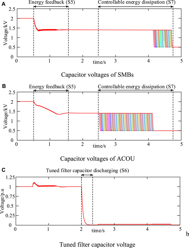
FIGURE 12. Simulation results of voltages during the stop process. (A) Capacitor voltages of SMBs. (B) Capacitor voltages of ACOU. (C) Tuned filter capacitor voltage.
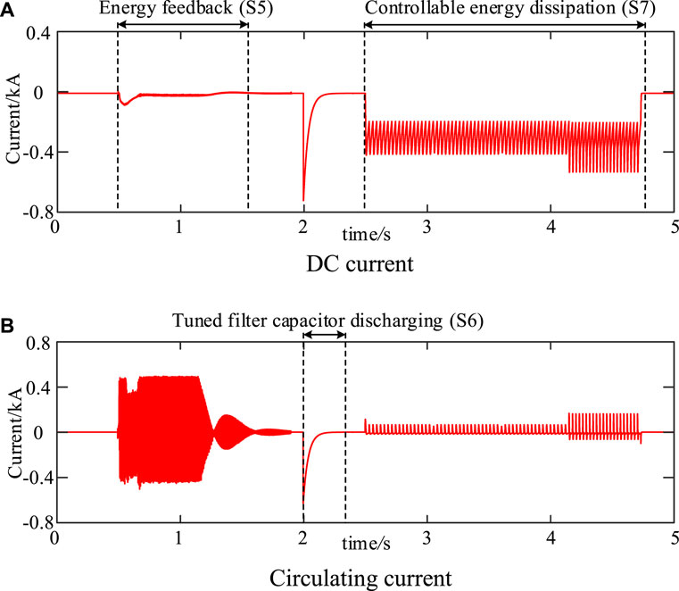
FIGURE 13. Simulation results of currents during the stop process. (A) DC current. (B) Circulating current.
6 Experimental results
6.1 Experimental hardware
The hardware-in-the-loop experiments are conducted in the RT-LAB real time simulator and a general-purpose DSP controller, which is shown in Figure 14. The step time of RT-LAB is 10μs and the control frequency of DSP is 20 kHz. The parameters used in the experiments is also from Table 1. The host computer is used to establish the real-time simulation model in RT-LAB and program in the DSP controller. RT-LAB and DSP controllable communicate through a transfer board. The electrical quantities such as the voltages and currents would be measured and sampled firstly. Then those signals are transmitted to the DSP controller and the control signal are acquired and transmitted back to the RT-LAB to control the model of the hybrid DC converter. The host computer can control all the switches and decide the implementation of the control modules. The results are outputted by the RT-LAB and displayed in the scope.
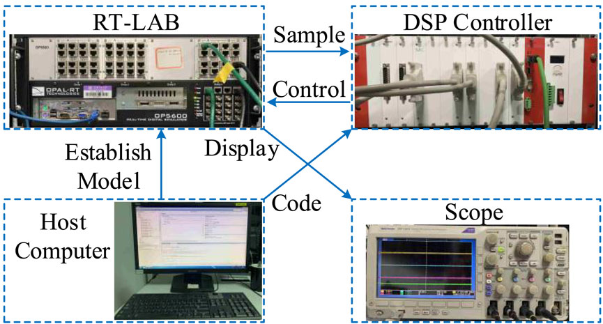
FIGURE 14. Experimental hardware.
6.2 Experimental verification
Figure 15 shows the experimental results of the start-up and shut-down process. All the stages during the process are switched manually. Therefore, Stages S1-S7 are not continuous. The meanings of S1-S7 are the same as the simulation results discussed in Section 5. In the experimental results, uc1 is the voltage of the submodule capacitors in SMBs. uc2 is the voltage of the submodule capacitors in ACOU. ubp is the voltage of the tuned filter capacitor. Icir is the current flowing to the tuned filter. Since the submodules set in the experiments are not affected by the self-power supply, all the submodules can be fully discharged during the controllable energy dissipation stage. Figure 15A shows that the tuned filter capacitor is fully charged and the submodule capacitors are partly charged. uc1 is still 3 times of uc2 after the uncontrollable precharging stage S1. In S2, the circulating voltages are established in SMBs and ACOU. As a result, the capacitor voltages in SMBs and ACOU are balanced in S3 by the circulating current. In S4, all the submodules in the auxiliary converter are fully charged.
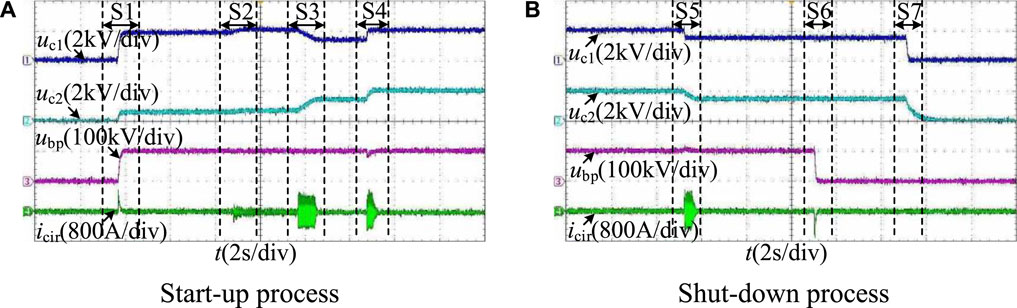
FIGURE 15. Experimental results. (A) Start-up process. (B) Shut-down process.
In S5, the shut-down process begins. Part of the storage energy in the submodules is fed back to the HVDC link. In S6, the tuned filter capacitor is fully discharged by the dissipation resistor. All the submodules can be fully discharged in S7. The experimental results are highly consistent with the simulation results and the analysis, which verify the validity of the proposed start-up and shut-down strategy of the hybrid dc converter.
7 Conclusion
This paper proposes a start-up and shut-down strategy of the auxiliary converter, which is used in the DR based hybrid HVDC transmission system. For the start-up strategy, the design method of the current-limiting resistor is introduced and the precharging current of the capacitors in the auxiliary converter can be restricted below the limited value. The relationship of the capacitor voltages between SMBs and ACOU is also derived. In order to balance the energy in the auxiliary converter, a circulating current control is proposed based on the characteristics of this topology. After the energy is balanced, the capacitor voltages are charged to the rated value through the dc current control. For the shut-down strategy, the energy is firstly fed back to the HVDC link by the mirroring process of the controllable precharging strategy. Then the remaining energy in the capacitors are consumed by the dissipation resistor. The proposed start-up and shut-down strategies can guarantee the submodule capacitors to be fully charged and discharged with minimal cost. The feasibility of the proposed strategies is proved both by the simulations and hardware-in-the-loop experiments.
Data availability statement
The original contributions presented in the study are included in the article/supplementary material further inquiries can be directed to the corresponding author.
Author contributions
ZF is responsible for the research on the start-up and shut-down strategies. RY is responsible for the establishment of the experimental platform. KH is responsible for the validation of the proposed methods. XC is responsible for the research on the start-up and stop strategy together with ZF. BH is responsible for the establishment of the simulation model and analysis. LL is responsible for the design of the parameters used in the hybrid HVDC transmission system.
Funding
Project Supported by the Project of IGCT Based Novel Converter Development by China Electric Equipment Group Co., Ltd. (CEE-2022-B-01-01-006-XJ).
Conflict of interest
Authors KH, BH, and LL were employed by the Company Xuji Electric Co., Ltd.
The remaining authors declare that the research was conducted in the absence of any commercial or financial relationships that could be construed as a potential conflict of interest.
The authors declare that this study received funding from Project of IGCT Based Novel Converter Development by China Electric Equipment Group Co., Ltd. The funder had the following involvement in the study: Validation of the proposed methods; Design of the parameters.
Publisher’s note
All claims expressed in this article are solely those of the authors and do not necessarily represent those of their affiliated organizations, or those of the publisher, the editors and the reviewers. Any product that may be evaluated in this article, or claim that may be made by its manufacturer, is not guaranteed or endorsed by the publisher.
References
Abu-Ali, M., and Colak, I. (2022). “A fast and safe discharging method for MMC submodule capacitors,” in 2022 International Exhibition and Conference for Power Electronics, Intelligent Motion, Renewable Energy and Energy Management, Nuremberg, Germany, 10-12 May 2022, 1–5. doi:10.30420/565822257
Bidadfar, A., Saborío-Romano, O., Cutululis, N. A., and Sørensen, P. E. (2021). Control of offshore wind turbines connected to diode-rectifier-based HVdc systems. IEEE Trans. Sustain. Energy 12, 514–523. doi:10.1109/TSTE.2020.3008606
Blasco-Gimenez, R., Añó-Villalba, S., Rodríguez-D'Derlée, J., Morant, F., and Bernal-Perez, S. (2010). Distributed voltage and frequency control of offshore wind farms connected with a diode-based HVdc link. IEEE Trans. Power Electron. 25, 3095–3105. doi:10.1109/TPEL.2010.2086491
Cardiel-Álvarez, M. Á., Arnaltes, S., Rodriguez-Amenedo, J. L., and Nami, A. (2018). Decentralized control of offshore wind farms connected to diode-based HVdc links. IEEE Trans. Energy Convers. 33, 1233–1241. doi:10.1109/TEC.2018.2804662
Chang, Y., and Cai, X. (2019). Hybrid topology of a diode-rectifier-based HVDC system for offshore wind farms. IEEE J. Emerg. Sel. Top. Power Electron. 7, 2116–2128. doi:10.1109/jestpe.2018.2881768
Das, A., Nademi, H., and Norum, L. (2011). “A method for charging and discharging capacitors in modular multilevel converter,” in IECON 2011 - 37th Annual Conference of the IEEE Industrial Electronics Society, Melbourne, VIC, Australia, 07-10 November 2011, 1058–1062. doi:10.1109/IECON.2011.6119454
Dekka, A., Wu, B., and Zargari, N. R. (2017). Start-up operation of a modular multilevel converter with flying capacitor submodules. IEEE Trans. Power Electron. 32, 5873–5877. doi:10.1109/TPEL.2017.2660399
Fang, Z., Cai, X., Shi, X., Lv, J., Yang, R., and Rao, F. (2022). Diode rectifier-based hybrid high-voltage direct current converter for offshore wind farms. IET Renew. Power Gener. 2022, 1–13. doi:10.1049/rpg2.12644
Jain, A., Saborío-Romano, O., Sakamuri, J. N., and Cutululis, N. A. (2021). Blackstart from HVDC-connected offshore wind: Hard versus soft energization. IET Renew. Power Gener. 15, 127–138. doi:10.1049/rpg2.12010
Karaagac, U., Cai, L., and Mahseredjian, J. (2017). “Simulation of startup sequence of an offshore wind farm with MMC-HVDC grid connection,” in 2017 IEEE Power and Energy Society General Meeting, Chicago, IL, USA, 16-20 July 2017, 1. doi:10.1109/PESGM.2017.8274723
Li, X., Liang, S., Li, Y., Yao, L., Huang, R., and Wang, Z. (2020). “Start-up strategy for DR-MMC paralleled hybrid HVDC integrated with offshore wind power,” in 2020 IEEE 4th Conference on Energy Internet and Energy System Integration, Wuhan, China, 30 October 2020 - 01 November 2020, 665–669. doi:10.1109/EI250167.2020.9346673
Lyu, J., Zhang, X., Cai, X., and Molinas, M. (2019). Harmonic state-space based small-signal impedance modeling of a modular multilevel converter with consideration of internal harmonic dynamics. IEEE Trans. Power Electron. 34, 2134–2148. doi:10.1109/TPEL.2018.2842682
Nami, A., Liang, J., Dijkhuizen, F., and Demetriades, G. D. (2015). Modular multilevel converters for HVDC applications: Review on converter cells and functionalities. IEEE Trans. Power Electron. 30, 18–36. doi:10.1109/TPEL.2014.2327641
Nami, A., Rodriguez-Amenedo, J. L., Arnaltes, S., Cardiel-Álvarez, M. Á., and Baraciarte, R. A. (2020). Frequency control of offshore wind farm with diode-rectifier-based HVdc connection. IEEE Trans. Energy Convers. 35, 130–138. doi:10.1109/TEC.2019.2949892
Nguyen, T. H., Lee, D. –C., and Kim, C. -K. (2014). A series-connected topology of a diode rectifier and a voltage-source converter for an HVDC transmission system. IEEE Trans. Power Electron. 29, 1579–1584. doi:10.1109/TPEL.2013.2283368
Pan, J., Ke, Z., Sabbagh, M. A., Na, R., Zhang, J., Wang, J., et al. (2018). “A novel discharging control strategy for modular multilevel converter submodules without using external circuit,” in 2018 IEEE Energy Conversion Congress and Exposition (ECCE), Portland, OR, USA, 23-27 September 2018, 656–661. doi:10.1109/ECCE.2018.8557997
Ramachandran, R., Poullain, S., Benchaib, A., Bacha, S., and Francois, B. (2019). “On the black start of offshore wind power plants with diode rectifier based HVDC transmission,” in 2019 21st European Conference on Power Electronics and Applications (EPE '19 ECCE Europe), Genova, Italy, 03-05 September 2019, 1–10. doi:10.23919/EPE.2019.8914779
Shi, X., Liu, B., Wang, Z., Li, Y., Tolbert, L. M., and Wang, F. (2015). Modeling, control design, and analysis of a startup scheme for modular multilevel converters. IEEE Trans. Industrial Electron. 62, 7009–7024. doi:10.1109/TIE.2015.2436354
Tian, K., Wu, B., Du, S., Xu, D., Cheng, Z., and Zargari, N. R. (2016). A simple and cost-effective precharge method for modular multilevel converters by using a low-voltage DC source. IEEE Trans. Power Electron. 31, 5321–5329. doi:10.1109/TPEL.2015.2484222
Wang, C., Lv, W., Lu, Y., Xu, F., and Qiu, P. (2019). Start-up scheme for converter station of MMC-HVDC based on single-clamp sub-module using in grid black start. J. Eng. 2019, 1892–1896. doi:10.1049/joe.2018.8696
Wang, P., Zhang, X. –P., Coventry, P. F., and Zhang, R. (2016). Start-up control of an offshore integrated MMC multi-terminal HVDC system with reduced DC voltage. IEEE Trans. Power Syst. 31, 2740–2751. doi:10.1109/TPWRS.2015.2466600
Xu, L., Luo, Y., Song, Y., and Blaabjerg, F. (2021). A smooth startup strategy for hybrid MMC based HVDC systems. Int. J. Electr. Power and Energy Syst. 133, 107315. doi:10.1016/j.ijepes.2021.107315
Xue, Y., Xu, Z., and Tang, G. (2014). Self-start control with grouping sequentially precharge for the C-MMC-based HVDC system. IEEE Trans. Power Deliv. 29, 187–198. doi:10.1109/TPWRD.2013.2279106
Yang, M., Cai, X., Wusiman, A., Zhang, J., and Lyu, J. (2022). Distributed-diode-rectifiers-based offshore wind power MVDC direct-transmission system. IEEE Trans. Energy Convers. 37, 643–653. doi:10.1109/TEC.2021.3110525
Yu, Z., Cou, L., Song, Q., Wang, J., Zhao, B., Tang, B., et al. (2022). “Black-start strategy of the HVDC system based on series-connected hybrid converter for offshore wind farms,” in 18th International Conference on AC and DC Power Transmission, Online Conference, China, 02-03 July 2022, 1153–1157. doi:10.1049/icp.2022.1364
Zeng, R., Xu, L., Yao, L., and Morrow, D. J. (2015). Precharging and DC fault ride-through of hybrid MMC-based HVDC systems. IEEE Trans. Power Deliv. 30, 1298–1306. doi:10.1109/TPWRD.2014.2360042
Zhang, L., Qin, J., Wu, X., Debnath, S., and Saeedifard, M. (2017). A generalized precharging strategy for soft startup process of the modular multilevel converter-based HVDC systems. IEEE Trans. Industry Appl. 53, 5645–5657. doi:10.1109/TIA.2017.2736958
Keywords: VSC-HVDC, hybrid DC converter, start-up and shut-down strategy, MMC, offshore wind farms
Citation: Fang Z, Yang R, Han K, Cai X, Hong B and Liu L (2023) Start-up and shut-down strategies of DR-based hybrid DC converter for offshore wind power transmission system. Front. Energy Res. 11:1091447. doi: 10.3389/fenrg.2023.1091447
Received: 07 November 2022; Accepted: 17 February 2023;
Published: 01 March 2023.
Edited by:
Fernando Martinez-Rodrigo, University of Valladolid, SpainReviewed by:
Liansong Xiong, Xi’an Jiaotong University, ChinaFeng Wang, Xi’an Jiaotong University, China
Copyright © 2023 Fang, Yang, Han, Cai, Hong and Liu. This is an open-access article distributed under the terms of the Creative Commons Attribution License (CC BY). The use, distribution or reproduction in other forums is permitted, provided the original author(s) and the copyright owner(s) are credited and that the original publication in this journal is cited, in accordance with accepted academic practice. No use, distribution or reproduction is permitted which does not comply with these terms.
*Correspondence: Xu Cai, eHVjYWlAc2p0dS5lZHUuY24=