 Kai Zhao1,2
 Xiaoxia Sun
- 1China North Vehicle Research Institute Department of Propulsion Systems Technology, Beijing, China
- 2State Key Laboratory of Intelligent Control and Decision Making for Complex Systems, Beijing Institute of Technology, Beijing, China
With the continuous progress of automotive new energy technology, the motor has become an important part of the power system, and the heat dissipation of insulated-gate bipolar transistors (IGBT) determines the reliability of the power system. Minichannel structure can be added to the thermal management system of new energy vehicles to improve the heat transfer capacity. Due to the growth of the boundary layer in the smooth minichannel flow channel, the cooling performance improvement was limited. Pin-fins and rib structures were used to break the boundary layer and increased the heat transfer area to enhance the heat transfer capacity. In this study, a numerical simulation model of minichannel with triangular pin-fins with different rotation angles was established and calculated using the SST k-omega method. The temperature field, velocity field, pressure, and vortex distribution under different configurations were discussed in detail. The jet area formed by the prism wall and the side wall of the minichannel would impact the wall and reduce the growth of the boundary layer. However, the stagnation area generated in the center and corner will reduce the improvement of heat transfer capacity. The thermo-hydraulic characteristics of different configurations at different Reynolds numbers (Re), such as Nusselt number (Nu), Darcy friction resistance coefficient (f), and performance evaluation criterion (PEC), were analyzed. As Re increased, the best and worst configurations changed, the best configuration changed from the 90°–120° structure to the 120°–120° structure, and the worst configuration changed from the 75°–60° to the 60°–60° structure. When the Re = 663, the influence of the front and rear rotation angle on the cooling performance was explored. When the rotation angle was closer to 60°, the cooling performance of the minichannel was better. And the closer the rotation angle was to 120°, the cooling performance was better. This has a reference effect on the design of minichannel heat sinks.
1 Introduction
As the trend of electrification of automotive components continues to develop, an increasing number of electronic devices are currently used in vehicles (Masias et al., 2021). In the powertrain of a hybrid electric vehicle, the motor is the power output device, and the battery is the energy storage device. Alternating current (AC) must first be converted from the direct current (DC) that the battery pack supplies to the motor (Marshall et al., 2019). To guarantee safe operation, the IGBT is a crucial component of the inverter that transmits a lot of energy during operation. And thus, the energy management system of IGBT must be efficient and reliable. The lifespan of current battery packs can be reduced as well, heat management is needed to guarantee longevity (Guo et al., 2022; Jaffal et al., 2023). The issue of thermal deterioration has emerged with the increasing performance of IGBT. To increase the efficiency of the thermal management system, higher-performance heat sinks must be used (Dong X et al., 2019; Chen et al., 2022a). Due to the limited space on board, it is necessary to study the efficient heat exchanger for the design of the new energy vehicle thermal management system.
Generally speaking, the smaller the diameter of the channel, the higher the heat transfer coefficient (Lee et al., 2014; Huo et al., 2015). Therefore, the use of minichannel heat sinks is a significant measure to improve heat transfer ability. The minichannel heat sink has a low power consumption, higher heat dissipation efficiency, and a compact structure. The requirement for smaller size and lighter weight in many industrial applications is the primary driver of the current demand for micro heat exchangers. Minichannels can be used as tiny heat exchangers because of their superior thermal performance. These heat exchangers are connected to higher pressure drops, nevertheless, with considerable thermal power. In order to maintain the best balance between heat transfer gain and pressure drop loss, the actual design of the heat exchanger essentially entails selecting an optimal solution. Besides, it is very effective in the process of heat dissipation of high-performance modern electronic equipment (Hao et al., 2016; Zhang et al., 2022).
However, with the development of the flow, a thermal boundary layer is formed, which makes the flow heat transfer performance significantly degraded (Tikadar et al., 2020; Kumavat et al., 2022). Therefore, many techniques are used to interfere with the growth of the boundary layer and enhance the cooling performance of the heat sink (Liu et al., 2022; Tian et al., 2022). Nanofluids, like three-dimensional graphene nanofluid, were used as coolant media to change the fluid physical parameters, which was widely used in the cooling process of chips (Bo et al., 2020). In addition, changing the geometry, using vortex generation structure, and performing flow disruption are very effective ways (Zheng et al., 2022a). Ma et al. (2022) found that in the boiling heat exchange process, in comparison to the smooth plane, minichannel with micro-pin-fins can lower pressure drop and thermal resistance by more than 30%. Guan et al. (2016) experimentally investigated the flow and convective heat transfer characteristics of the circular, diamond, and triangular micro pin fins at different thermal loads in the Reynolds number (Re) range from 0 to 1,000. The pressure drop, friction factor, thermal resistance, and the Nusselt number (Nu) of micro pin fins with different cross-sectional shapes were obtained at thermal loads of from 50 to 150 W. Hosseinirad and Hormozi (2017) used numerical simulations to investigate the effect of shape, position, and the number of flow disturbance ribs on Nu, pressure drop, and thermal resistance of microchannels; Ye et al. (2022) designed a minichannel with fan-shaped cavities and elliptical pin fins. And the effects of cavity height, chord Length, rib offset distance, and rib height on performance evaluation criterion (PEC) were discussed. Li et al. (2022) proposed a bionic heat sink with a micro crescent-shaped dune hump for improving the flow and heat transfer performance in a smooth narrow channel. The findings demonstrated that the micro crescent-shaped dune hump can boost local heat transfer performance by inducing secondary flow downstream of the slip surface.
Many heat sink configurations with flow disturbance structures have been studied, ranging from those with ribs on the side walls to those with ribs and vortex generators on the bottom (Datta et al., 2019). After the fluid passes through the vortex generator, the pressure difference between its two sides causes the fluid to separate from the edges and create vortices, which effectively impact the boundary layer and redistribute the temperature field. The secondary flow enables the core flow to mix with the fluid near the wall to improve heat transfer efficiency. The cross-flow generated by the vortex can further reduce the thickness of the boundary layer (Saravanan et al., 2018; Al Muallim et al., 2020). The ribs on the side walls have a limited effect on the boundary layer of the flow channel, and the cooling performance is improved more significantly by the addition of ribs or vortex generator configuration at the bottom (Datta et al., 2019). Many studies have investigated the effect of different configurations on minichannel cooling performance (Hithaish et al., 2022; Kim et al., 2022). Zheng et al. studied the effect of the height arrangement of the ribs added at the bottom on the heat transfer coefficient in the microchannel flow channel and proposed an optimization method to obtain the optimal configuration (Zheng et al., 2022b). To find the best geometry of pin-fins, Tullius et al. (2012) modeled microchannels using pin-fins. Six pin-fin shapes—circular, square, triangular, elliptical, rhombic, and hexagonal—were analyzed on the rectangular microchannel’s bottom heat surface. The researchers obtained correlation coefficients for the Nu and the Darcy friction factor (f). Among all the configurations, triangular fins with larger fin height, smaller fin width, and spacing double the fin width maximized the number of fins in each row and yields better performance, the Nu was maximum. Wong and Lee (2015) analyzed the thermal and hydraulic performance of silicon-based minichannels with different geometrical parameters of triangular ribs arranged in transverse microchambers. The parametric variables of width, length, and height of the triangular ribs were investigated. It was found that the triangular ribs with a width of 100 μm, length of 400 μm, and height of 120 μm had the best geometrical parameters for Re = 500. The maximum PEC was 1.43 and the increase in Nu was 56%, under the condition of equal pumping power.
Among all the shapes, it can be seen that the triangular shape has more advantages than other shapes in promoting flow separation and circulation in the minichannels. This makes the triangular prism good for flow destruction. The triangular pin-fin heat sink is therefore the central issue of this paper. Hithaish et al. (2022). At present, there are many studies on the shape, height, number, and arrangement of vortex generators. But there is less discussion about the impact of the triangular pin-fin direction on heat sinks' ability to cool, and the vortex generation has not been quantitatively assessed (Yang et al., 2022). In general, the arrangement of triangular pin-fins in minichannels has not been well discussed quantitatively.
Therefore, in this work, the impacts of the front and rear pin-fin rotation angles on the cooling performance of triangular pin-fins in minichannel were discussed. Firstly, the CFD model of single-channel smooth microchannel was established and compared with the experimental results to verify the reliability of the model. Secondly, the triangular pin-fins were added, and the rotation angles of the front and rear prisms were changed to calculate the relevant parameters. The new vortex criterion, the omega criterion, was used to calculate the vortices in the heat sink and to observe the effect of fin pin orientation on vortex formation. The effects of different rotation combinations and Re on flow heat transfer characteristics were discussed, including Nu, f, and PEC. And find the optimal combination of the pin-fins angle design. This method can guide the design of the IGBT heat dissipation channel.
2 Numerical simulation
2.1 Physical model
As the minichannels were all identical in structure between each channel, only the thermal-hydraulic characteristics of a single microchannel were analyzed to reduce computational resources. To highlight the influence of the configuration on thermal-hydraulic performance, the following simplifications and assumptions were made. The cooling mass in the channel was an incompressible Newtonian fluid and the state of flow was a steady-state laminar flow. The physical properties of the solids and liquids did not vary with temperature. The heat dissipation between the heat sink and the environment was ignored in the simulations. The contact thermal resistance between the heating wall and the heating source was ignored.
The geometry of the chosen minichannel heat sink is shown in Figure 1. Figure 1A shows a schematic of the overall structure. As the plastic cover plate was put over the minichannel, this intersection was set as the adiabatic wall surface. The surfaces where the coolant and minichannel were in contact were set as the fluid-solid coupled surface when simulating. Figure 1B shows the geometry of the minichannel cross-section. Two triangular pin-fins were set up in the minichannel and their configuration was shown in Figures 1C, D. Orientations of the pin-fins were changed, the angle changed at the front was called the “front rotation angle”, and the angle changed at the rear was called the “rear rotation angle”. The rotation angle values vary from 15° to 120°. The interval was 15° and a total of 64 configurations were designed. In the subsequent simulations, the flow and heat transfer properties were discussed for different configurations and flow rates.
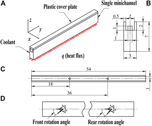
FIGURE 1. The geometry of minichannel: (A) 3D model; (B) cross-section of minichannel; (C) the arrangement of two triangular pin-fins; (D) the front rotation angle and rear rotation angle of the pin-fins.
2.2 Governing equations and boundary conditions
The SST k-
Continuity:
Where
Momentum:
Where p presents the pressure,
Turbulent kinetic energy:
Where k is the turbulent kinetic energy, G is the generation of turbulent kinetic energy,
Specific dissipation rate:
Where
Energy:
Where
Energy conversion formulae for solid domain:
The material of the minichannel was oxygen-free copper with the thermal conductivity of 387.6 W/(m·K), the coolant was distilled water and the physical parameters were constants at 25°C. The velocity inlet was set and the inlet velocity was increased from .1 to .3 m/s. The outlet was set as a pressure outlet and the pressure was set to atmospheric pressure. The heat flow density of the heat source was set to 100,000 W/m2 (Chen et al., 2022b). In addition to the heating source, the other walls were set to be adiabatic, and the coupled algorithm was used, with the energy, momentum, and pressure in second order windward differential format, and the residuals for the continuous, momentum, and energy equations was 10−6.
The numerical results will change depending on the size of the grid. To choose a grid size that balances accuracy and computational cost, grid-independence verification must be carried out, as shown in Figure 2. Too few grids will result in subpar accuracy, but too many grids will raise computation costs with no gain in accuracy. Therefore, the mesh size was set to 0.1 mm to meet the accuracy and computation time of the simulation, and the number of grids reached 3,764,518, as shown in Figure 3. The commercial software Fluent was chosen as the solver for the simulation.
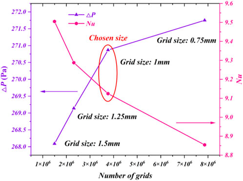
FIGURE 2. Grid-independence verification. The pink and purple lines represent the Nu and pressure drop, respectively.
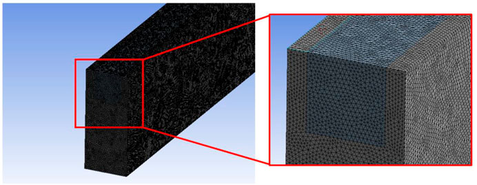
FIGURE 3. The schematic diagram of 0.1 mm meshing.
2.3 Parameter definitions
The velocity and material properties of fluid with the geometry of minichannel determines the Re (Ebrahimi et al., 2016):
Where
Where
Average heat transfer coefficient (h) of the minichannel can be represented by Chen et al. (2022b):
Where
Average Nusselt number (Nu) of the minichannel can be represented by Ebrahimi et al. (2016):
Average Darcy friction resistance coefficient (f) can be represented by Chen et al. (2022b):
Where
PEC is the comprehensive evaluation of the thermal-hydraulic characteristics of minichannel with pin-fin (Ebrahimi et al., 2016; Chen et al., 2022b):
Where the subscript 0 represents the thermal-hydraulic characteristics of smooth minichannel as the reference value. Hence, the PEC of smooth minichannel is always 1.
The omega criterion is a new vortex identification method that normalizes the vortices generated in the flow field. The omega criterion value (
Where
2.4 Validation of the numerical method
In this paper, the minichannel model in (Chen et al., 2022b) was modeled and simulated, and the numerical results were compared with the experimental data to verify the reliability of the numerical method. The width and height of the minichannel heat sink are 25 mm and 150mm, respectively, with a total of eight channels and a section of 2 mm width and 2 mm height, as shown in Figure 4.
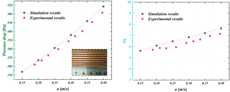
FIGURE 4. Comparison of experimental results (Chen et al., 2022b) and simulation results of △P (pressure drop) and Nu.
Figure 4 shows the results. It can be seen that for the pressure drop, the simulation results in his paper had a small error compared to the experimental results, with a maximum error of 7.1%. The Nu error of the simulation was slightly larger, with a maximum error of 9.0%. The simulation error was slightly larger than the test value, mainly because there were some errors in the manufacturing process. Besides, the dynamic viscosity in the setting of physical parameters might be slightly larger. Overall, the errors in the calculated results compared to the experimental ones were within acceptable limits.
3 Results and discussion
3.1 The thermal and hydraulic characteristics of triangular pin-fins in the minichannel heat sink
Figure 5 shows the contours of velocity, pressure, temperature, and omega criterion values at the planes for the 60°–60° structure. It can be seen that the velocity distribution was rather uneven, especially in the area after the fluid passed through the prism. The velocity near the wall was close to zero. The water velocity of the core flow was so fast, reaching .73 m/s, which reduced the pressure. The surrounding fluid converged inwards with a return flow near the wall, which is very slow and forms a stagnant zone. In the stagnation zone, heat accumulated and could not be transferred to the core flow. This reduced the local heat transfer performance and a significant temperature rise can be seen. The bulge in the wall surface caused an abrupt change in fluid pressure, which occurred in front of and behind the prism. There was an abrupt increase at the front pin fin and a significant decrease at the rear. The smaller flow area would increase the local pressure due to Bernoulli’s equation. As can be seen from the temperature contours, after the first pin-fin the thermal boundary layer was broken and a jet was formed in the channel between the prism and the minichannel. This enhanced the heat transfer capacity of the minichannel. However, with the development of the fluid, the effect of this structure on the heat transfer performance was limited. The reason for this was the presence of a stagnant zone and the lack of homogeneous mixing. At the end of the minichannel, the temperature difference between the coolant and the wall was still high, with a maximum wall temperature of 313.36 K. The fluid was influenced by the pin-fins, which form vortices, concentrated in the core flow zone, which promoted a better exchange of temperature between the central flow and the wall surface.
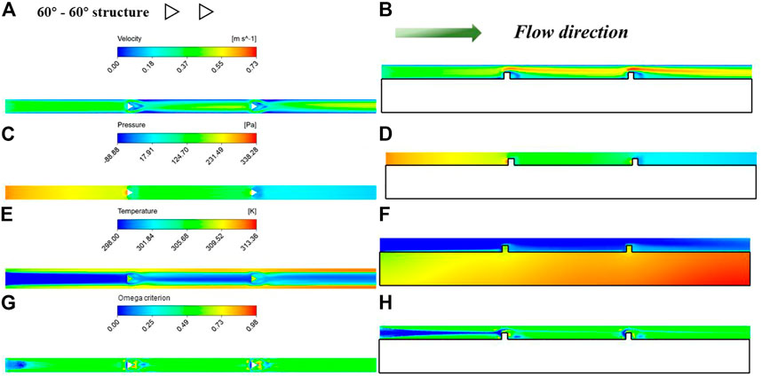
FIGURE 5. Contours of velocity, pressure, temperature and omega criterion values at the planes for the 60°–60° structure: (A, C, E, G) for the plane (z = 5.5 mm); (B, D, F, H) for the plane (y = 1.5 mm).
Figure 6 shows the contours of velocity, pressure, temperature, and omega criterion values at the planes for the 120°–120° structure. The fluid heat transfer is similar to the 60°–60° structure. There was a significant increase in flow velocity when flowing through the pin-fins, reaching a maximum of .64 m/s, which was less than .73 m/s. The flow velocity was more evenly distributed at the outlet, indicating a more homogeneous mixing of the coolant, leading to better heat transfer performance. At the same time, the fluid passing through the prism impinged on the wall surface with the effect of the column surface guide, and the flow boundary layer was destroyed. This increased flow velocity near the walls, which contributes to heat transfer. As can be seen from the contours of the pressure, there were some abrupt changes. The contours for temperature show that the temperature boundary layer was broken at the prism, and some flow areas behind the prism became a stagnant zone. And thus, the fluid temperature raised, but the heat transfer was not effective. However, near the outlet, the fluid temperature was evenly distributed and there was an increase in temperature compared to the smooth plane, which was due to the uniform mixing, which enhanced the heat transfer at the wall. The maximum temperature at the wall was 311.43 K. Although vortices were still generated by the prism, they were more concentrated, mainly at the rear of the prism, where the secondary flow separated. The vortex volume was less than 60°–60° structure.
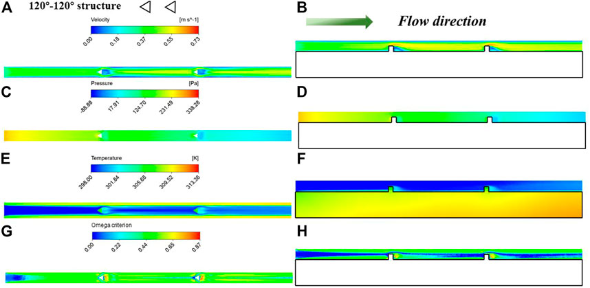
FIGURE 6. Contours of velocity, pressure, temperature and omega criterion values at the planes for the 120°–120° structure: (A, C, E, G) for the plane (z = 5.5 mm); (B, D, F, H) for the plane (y = 1.5 mm).
Figure 7 shows the contours of velocity, pressure, temperature, and omega criterion values at the planes for the smooth minichannel. Due to the velocity boundary layer, the flow velocity near the wall was close to 0. As the flow developed, the velocity boundary layer increased and the velocity of the central flow increased, reaching .57 m/s at the outlet. Due to the inlet effect, there was a significant decrease in pressure near the inlet. Then, the pressure decreased, which dropped to 0 at the outlet. As can be seen from the contours of temperature, the smooth minichannel produces a distinct temperature boundary layer. Near the wall, the temperature of the fluid raised, but this temperature was not transferred to the core flow, allowing the wall temperature to rise to 322.30 K. Since the Re was only 663 at a flow velocity of .3 m/s, the flow of the coolant was laminar for the smooth minichannel, with no significant vortex generation.
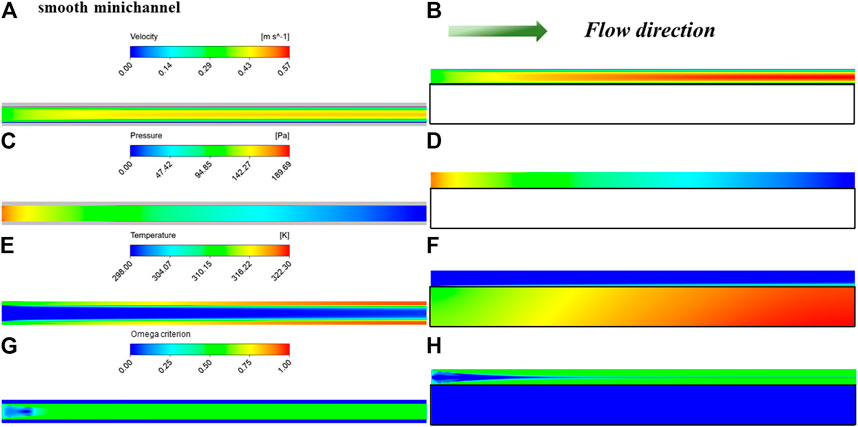
FIGURE 7. Contours of velocity, pressure, temperature and omega criterion values at the planes for the smooth minichannel: (A, C, E, G) for the plane (z = 5.5 mm); (B, D, F, H) for the plane (y = 1.5 mm).
Figures 8, 9, 10 show the contours of velocity, temperature, and omega criterion values on different spanwise cross-sections for different minichannel configurations, respectively. Boundary layer effects can be observed for the smooth minichannel. For the minichannel with pin-fins, there was some reduction in the boundary layer thickness. However, due to the abrupt change in height, caused by the fins, there was an abrupt change in the flow velocity. Due to the obstruction of the fins, the flow velocity at the rear was very slow and a stagnant zone was formed in the area near the edge of the prism, as can be seen in the x1 and x3 planes. For the 60°–60° structure, in the x2 and x4 plane, there was a clear stagnant zone at the corner, where the flow velocity was close to 0. Although the fluid temperature was raised, the heat transfer ability deteriorated. The increase in flow velocity was noticeable, reaching a maximum of .73 m/s in the core flow area as the flow develops. As for the 120°–120° structure minichannel, the smaller stagnant zone led to better heat transfer characteristics. Besides, the velocity distribution of the 120°–120° structure minichannel was more even. The increase in flow velocity was small, close to the smooth minichannel in the central region as the flow develops, at approximately .58 m/s.
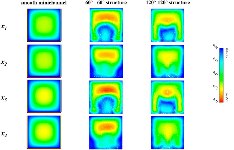
FIGURE 8. Contours of velocity on different spanwise cross-sections for different minichannel configurations: x1 = 19mm; x2 = 20.5mm; x3 = 37mm; x4 = 38.5 mm.
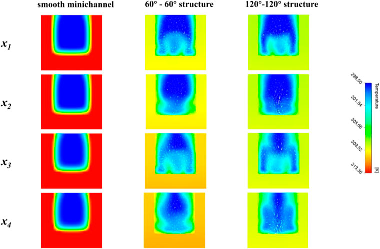
FIGURE 9. Contours of temperature on different spanwise cross-sections for different minichannel configurations: x1 = 19mm; x2 = 20.5mm; x3 = 37mm; x4 = 38.5 mm.
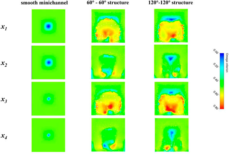
FIGURE 10. Contours of omega criterion values on different spanwise cross-sections for different minichannel configurations: x1 = 19mm; x2 = 20.5mm; x3 = 37mm; x4 = 38.5 mm.
As can be seen from the contours of the temperature, the flow direction was complex due to the disturbance of the pin-fins, which broke the original direction of flow, which made the direction of flow overlap with the direction of heat transfer at the wall. This allowed the heat transfer performance of the minichannel to be improved. At the same time, the fluids in the low and high temperature zones were more evenly mixed, resulting in better heat transfer. At x2 and x4 there was a difference in the direction of flow between the 120°–120° structure and the 60°–60° structure. It can be seen that the 60°–60° structure had an upward flow line but the 120°–120° structure had a downward flow direction. As the fluid flowed through the wall, the wall temperature cooled further as the central flow was colder. The downward flow was able to bring the cooler fluid closer to the wall. In contrast, the upward flow was mixed by bringing the higher temperature fluid to the central flow, which resulted in a slightly lesser heat transfer enhancement than the former.
As can be seen from the contours of the omega criterion, for smooth minichannel, no vortices were generated because of the low kinetic energy of the fluid. For the minichannel with pin-fins, there were three places where vortices were generated - at the central flow and near the two corners of the wall. In the central flow, the abrupt change in the wall impeded the flow, reducing the pressure at the back of the prism and increasing the flow velocity at the top of the prism. The flow velocity was lower near the prism walls, and this difference in velocity created a secondary flow. At the corners, the flow was guided by the prism walls towards the center and the slower flow velocities were separated, creating a backflow. For the 60°–60° structure, this backflow resulted in a significant reduction in flow velocity, while for the 120°–120° structure, the loss of velocity was less. This was because the 60°–60° structure had a faster flow velocity and a higher coiling capacity as the fluid bypassed the pin-fins. The vortices at x1 and x3 were concentrated in the central area, while the vortices at x2 and x4 were concentrated at the bottom of the minichannel, which was due to the lower temperature in the central basin of the smooth minichannel. The vortices generated by the disturbed pin-fins were able to mix the fluid inside the minichannel sufficiently to intensify the heat transfer at the walls.
In general, it was discovered that the jet zone created by the minichannel row’s prismatic wall surface and side walls would diminish heat boundary layer development, while the stationary zone created at the center and corner would lessen the improvement in heat transfer capacity.
3.2 The effects of Re on cooling performance
Figure 11 shows the effects of Re on cooling performance, as the front rotation angle is 30°. The rear rotation angle increased from 30° to 120°. When the Re raised from 221 to 663, the Nu increased, while the f decreased. For the Nu, the 30°–120° structure shows the best performance. Besides, all these configurations were better than the smooth minihcannel, because of the disturbance effect of pin-fins. It can be seen in Figure 11A, that the rate of increase in Nu of the minichannel with pin-fins was higher than for the smooth minichannel, as the Re increased. It can be seen in Figure 11B that, the f of each configuration was all higher than the smooth minichannel, and their values were quite near. The f of the 30°–60° structure was a little higher. Actually, in other studies, similar conclusions have been found. Under different Re, the optimal configuration will change. For example, the study in Chen et al. (2022b) shows that the optimal configuration changes twice when Re varied from 200 to 900. In this study, we discussed in more detail.
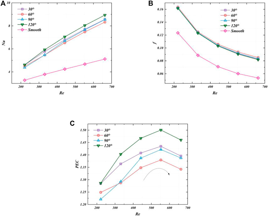
FIGURE 11. Effects of Re on cooling performance (front rotation angle = 30°): (A) Nu; (B) f; (C) PEC.
To better compare the flow heat transfer performance, the PEC was used in Figure 11C. It can be seen that for the same configuration when Re was lower than 552, the PEC increased as Re increased. After Re was higher than 552, the PEC decreased as Re increased. In the beginning, as the flow rate increased, the heat exchange between the central flow and the fluid at the boundary layer became more adequate, contributing to the cooling performance of the heat sink. After the flow velocity reached .25 m/s, a larger stagnation zone was created due to the higher velocity of the central flow, causing a deterioration in local heat dissipation and a decrease in the PEC. The 30°–120° structure presented the best cooling performance, followed by the 30°–30° structure. For the 30°–90° structure, the cooling performance increased the fastest. The 30°–60° structure performed poorly, mainly due to the low Nu and high f at the same Re. Overall, the thermal-hydraulic performance of the different configurations changed at Re was a variation. Therefore, it was necessary to find out the best conformation at different Re.
Therefore, the thermal-hydraulic characteristic would change at different Re. When Re increased, the optimum configuration changed from a 90°–120° structure to a 120°–120° structure, while the worst configuration moved from a 75°–60° structure to a 60°–60° structure. In addition, the PEC initially rose and subsequently fell. The maximum PEC for each configuration was attained at Re = 553.
3.3 The effects of pin-fins orientation on cooling performance
For a more detailed analysis at the same Re, the effect of rear rotation angle and front rotation angle on the cooling performance, some configurations were designed and simulated in the following work.
Figure 12 shows the effects of the rear rotation angle on cooling performance when the Re was 663. The different curves represent different front rotation angles. When the rear rotation angle was 60°, the Nu was the lowest and the f was medium, the PEC was lowest whatever the front angle value was. The PEC was the highest when the rear rotation angle was 120°. It reached 1.46, 1.40, 1.46, and 1.49 for the front angle rotation was 30°, 60°, 90°, and 120°, respectively.
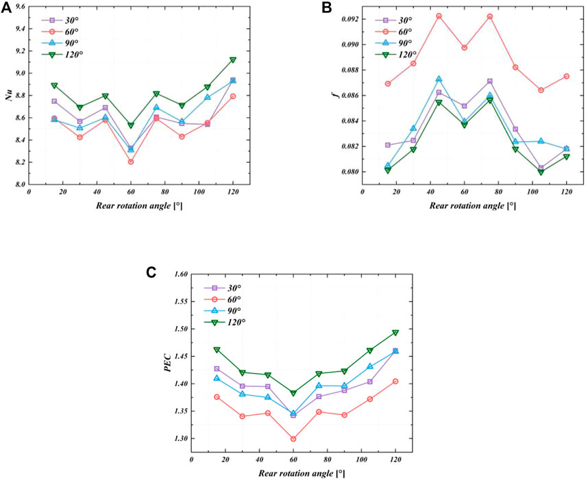
FIGURE 12. Effects of rear rotation angle on cooling performance (Re = 663): (A) Nu; (B) f; (C) PEC.
Figure 13 shows the effects of the front rotation angle on cooling performance when the Re was 663. The different curves represented different rear rotation angles. When the front rotation angle was 60°, the Nu was the lowest and the f was medium, the PEC was lowest whatever the front angle value was. The PEC was the highest when the front rotation angle was 120°. It reached 1.42, 1.38, 1.42, and 1.49 for the front angle rotation was 30°, 60°, 90°, and 120°, respectively. It can be seen that the effect of the front angle on the cooling effect of the heat sink was mainly through the effect on f. Before the front rotation angle reached 60°, the f increased by 8.0%, 7.2%, 7.9%, and 8.1% for the four different rear rotation angles, respectively. After the front rotation angle reached 60°, the f decreased by 7.6%, 6.8%, 7.3%, and 7.2% for the four different rear rotation angles, respectively. As the front rotation angle increased to 60°, Nu increased and f decreased, because of the increase in the area of the front part of the static hysteresis zone. When the front rotation reached 60°, the area of the stagnation zone reached the maximum, which was not conducive to the enhancement of the minichannel heat transfer. The flow resistance in the stagnation zone was high, the flow velocity was low, and the heat exchange was low, so f reached its peak and the Nu was the lowest, and PEC was the lowest under the effect of these two factors. Besides, compared to Nu, the effect of the front rotation angle on f was greater, indicating that the boundary layer growth was not obvious in the front part of the channel. Hence, the effect of the triangular prism on the boundary layer is smaller, but the obstruction to the flow is obvious.
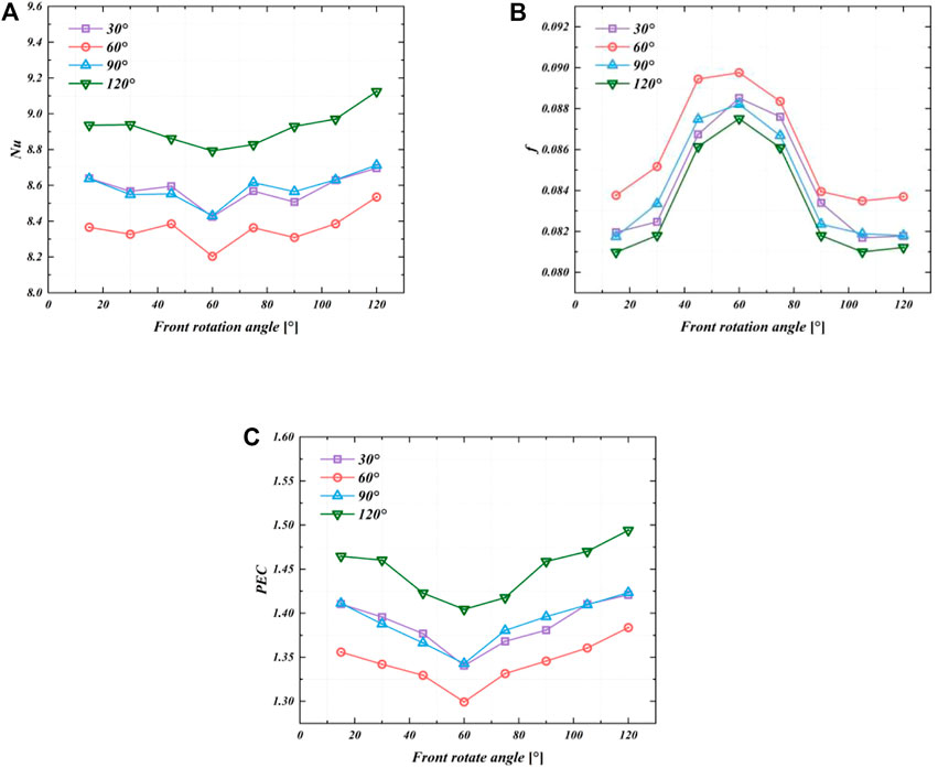
FIGURE 13. Effects of front rotation angle on cooling performance (Re = 663): (A) Nu; (B) f; (C) PEC.
To better reflect the synergistic effects of the front and rear rotation angles, the PEC values for the various configurations from 15° to 120° were compared, as shown in Figure 14. It can be seen that, as the 60°-60°structure was approached, the lower the PEC, while as the angle approached 120° and 15°, the higher the PEC value. The shape of surface was funnel-shaped, with the 60°-60°structure corresponding to the point at its center. It can be noticed that, among all these configurations, the 120°–120° structure still had the best cooling performance. This was because, at a rotation angle of 120°, a tight gap flow outlet was formed between the side of the pin-fins and the wall. The jet was generated further away, allowing a more intense mixing of the jet with the main flow, which helped to suppress the formation of the backflow zone behind the prism. This phenomenon can be seen in Figure 15, which shows the difference of the velocity profiles under the 120°–120° structure and the 60°-60°structure. The 60°–60° structure had the worst cooling performance, with its pin-fins forming an extended slit exit, which caused the backflow zone to be created closer to the prism. The uneven flow hindered further improvement of heat transfer performance. In general, among all the configurations, the isotropic structure, with the acute angles parallel to the entering flow, was the most effective configuration.
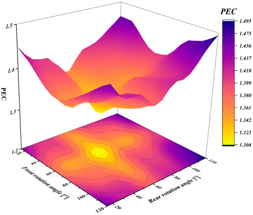
FIGURE 14. Effects of the front and rear rotation angle on PEC (Re = 663).
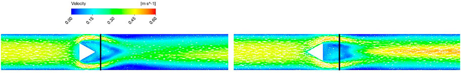
FIGURE 15. Comparison of the velocity profiles of the 120°–120° structure and the 60°–60°structure.
The same analysis was performed on different Re, and the optimum and worst minichannel configurations were obtained, as shown in Figure 16. It can be seen that when the Re was 221, the best configuration was the 90°–120° structure, and the worst configuration was the 75°-60°structure. When the Re was higher than 331, the best configuration was the 120°–120° structure, while the worst configuration was the 60°–60° structure. In conclusion, when the rear rotation angle = 120°, the cooling performance of the minichannel was better with Re variation. When the rear rotation angle = 60°, the cooling performance was poorer.
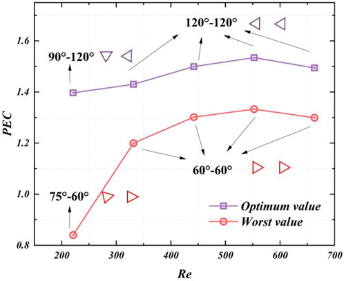
FIGURE 16. The optimum and worst minichannel configurations on different Re.
4 Conclusion
In this study, numerical simulation models of minichannel with triangular pin fins with different rotation angles were constructed, calculated using the SST k-omega method, and validated using smooth minichannel with the same cross-section. The omega criterion was used to observe the effect of fin pin orientation on vortex formation. The conclusions drawn from this study are the followings.
1) The triangular prism pin-fins can promote the heat transfer of minichannel. It was found that the jet zone formed by the prismatic wall surface and side wall of the minichannel row would impact the wall surface and reduce the growth of the boundary layer. The smooth minichannel had a maximum temperature 10 K higher than those with pin-fins.
2) As Re increased, the Nu increased and the f decreased, as the higher flow rates meant more heat exchange and more flow resistance. The PEC firstly increased and then decreased. At Re = 553, the PEC of each configuration reached its maximum.
3) At Re = 663, when the angle of rotation was closer to 60°, the worse the performance, and when the angle of rotation was closer to 120°, the better the performance. The 120° structure could generate the jet far away from pin-fins, resulting in a more homogeneous fluid mixing and improved thermal-hydraulic performance.
In view of the influence of pin-fin geometric configuration on the flow heat transfer process, there is no dimensionless evaluation index of rotation angle. If the number of pin-fin is large, the time cost of simulation is quite high. In the future, machine learning can be used to model the model and reduce the cost of finding the optimal configuration. In addition, the laminar single-phase flow at low Reynolds number was analyzed in detail in this paper. The influence of triangular pin-fin configuration on vortex distribution at high Reynolds number and turbulent flow can be further discussed.
Data availability statement
The raw data supporting the conclusion of this article will be made available by the authors, without undue reservation.
Author contributions
KZ, Conceptualization, methodology, simulation, writing—draft preparation; XS, Validation, methodology, simulation; YX, Validation, simulation, supervision; QL, Analysis, simulation; LS, Analysis, supervision; ML, writing.
Conflict of interest
The authors declare that the research was conducted in the absence of any commercial or financial relationships that could be construed as a potential conflict of interest.
Publisher’s note
All claims expressed in this article are solely those of the authors and do not necessarily represent those of their affiliated organizations, or those of the publisher, the editors and the reviewers. Any product that may be evaluated in this article, or claim that may be made by its manufacturer, is not guaranteed or endorsed by the publisher.
References
Al Muallim, B., Wahid, M. A., Mohammed, H. A., Kamil, M., and Habibi, D. (2020). Thermal–hydraulic performance in a microchannel heat sink equipped with longitudinal vortex generators (LVGs) and nanofluid. Processes 8 (2), 231. doi:10.3390/pr8020231
Bo, Z., Ying, C., Yang, H., Wu, S., Yang, J., Kong, J., et al. (2020). Highly thermo-conductive three-dimensional graphene aqueous medium. Nano-micro Lett. 12 (1), 138–142. doi:10.1007/s40820-020-00478-2
Chen, C., Zhao, H., Liu, C., Chen, J., Liu, C., Zhang, T., et al. (2022). Transient heat transfer characteristics in a flat plate heat sink with mini-channels for cooling high heat flux IGBT. Micromachines 13 (9), 1417. doi:10.3390/mi13091417
Chen, C., Feng, Z., Zhang, Q., Zhang, J., and Guo, F. (2022). Effects of regular triangular prisms on thermal and hydraulic characteristics in a minichannel heat sink. Int. J. Heat Mass Transf. 188, 122583. doi:10.1016/j.ijheatmasstransfer.2022.122583
Dong, X., Gao, Y., and Liu, C. (2019). New normalized Rortex/vortex identification method. Phys. Fluids 31 (1), 011701. doi:10.1063/1.5066016
Datta, A., Sanyal, D., Agrawal, A., and Das, A. K. (2019). A review of liquid flow and heat transfer in microchannels with emphasis to electronic cooling. Sādhanā 44 (12), 234–332. doi:10.1007/s12046-019-1201-2
Dong, F., Feng, Y., Wang, Z., and Ni, J. (2019). Effects on thermal performance enhancement of pin-fin structures for insulated gate bipolar transistor (IGBT) cooling in high voltage heater system. Int. J. Therm. Sci. 146, 106106. doi:10.1016/j.ijthermalsci.2019.106106
Ebrahimi, A., Rikhtegar, F., Sabaghan, A., and Roohi, E. (2016). Heat transfer and entropy generation in a microchannel with longitudinal vortex generators using nanofluids. Energy 101, 190–201. doi:10.1016/j.energy.2016.01.102
Guan, N., Jiang, G., Liu, Z. G., and Zhang, C. W. (2016). Effects of heating load on flow resistance and convective heat transfer in micro-pin-fin heat sinks with different cross-section shapes. Exp. Heat. Transf. 29 (5), 673–690. doi:10.1080/08916152.2015.1086841
Guo, Z., Xu, Q., and Ni, M. (2022). A numerical study on the battery thermal management system with mini-channel cold plate considering battery aging effect. Appl. Therm. Eng. 219, 119564. doi:10.1016/j.applthermaleng.2022.119564
Hao, X., Peng, B., Xie, G., and Chen, Y. (2016). Efficient on-chip hotspot removal combined solution of thermoelectric cooler and mini-channel heat sink. Appl. Therm. Eng. 100, 170–178. doi:10.1016/j.applthermaleng.2016.01.131
Hithaish, D., Saravanan, V., Umesh, C. K., and Seetharamu, K. N. (2022). Thermal management of Electronics: Numerical investigation of triangular finned heat sink. Therm. Sci. Eng. Prog. 30, 101246. doi:10.1016/j.tsep.2022.101246
Hosseinirad, E., and Hormozi, F. (2017). Influence of shape, number, and position of horizontal minifins on thermal-hydraulic performance of minichannel heat sink using nanofluid. Heat. Transf. Eng. 38 (9), 892–903. doi:10.1080/01457632.2016.1211920
Huo, Y., Rao, Z., Liu, X., and Zhao, J. (2015). Investigation of power battery thermal management by using mini-channel cold plate. Energy Convers. Manag. 89, 387–395. doi:10.1016/j.enconman.2014.10.015
Jaffal, H. M., Mahmoud, N. S., Imran, A. A., and Hasan, A. (2023). Performance enhancement of a novel serpentine channel cooled plate used for cooling of Li-ion battery module. Int. J. Therm. Sci. 184, 107955. doi:10.1016/j.ijthermalsci.2022.107955
Kim, K., Lee, H., Kang, M., Lee, G., Jung, K., Kharangate, C. R., et al. (2022). A machine learning approach for predicting heat transfer characteristics in micro-pin fin heat sinks. Int. J. Heat Mass Transf. 194, 123087. doi:10.1016/j.ijheatmasstransfer.2022.123087
Kumavat, P. S., Alimohammadi, S., and O’Shaughnessy, S. M. (2022). A computational conjugate heat transfer study of a rectangular minichannel undergoing sinusoidal flow pulsations. Int. J. Therm. Sci. 182, 107790. doi:10.1016/j.ijthermalsci.2022.107790
Lee, H., Park, I., Mudawar, I., and Hasan, M. M. (2014). Micro-channel evaporator for space applications–2. Assessment of predictive tools. Int. J. Heat Mass Transf. 77, 1231–1249. doi:10.1016/j.ijheatmasstransfer.2014.06.008
Lee, J., and Lee, K. S. (2013). Correlations and shape optimization in a channel with aligned dimples and protrusions. Int. J. Heat Mass Transf. 64, 444–451. doi:10.1016/j.ijheatmasstransfer.2013.04.055
Li, X. J., Zhang, J. Z., Tan, X. M., Zhang, Q. C., and Lu, E. H. (2022). Investigation of fluid flow and heat transfer in a narrow channel with micro barchan-dune-shaped humps. Int. J. Mech. Sci. 231, 107589. doi:10.1016/j.ijmecsci.2022.107589
Liu, C., Gao, Y. S., Dong, X. R., Wang, Y. Q., Liu, J. M., Zhang, Y. N., et al. (2019). Third generation of vortex identification methods: Omega and Liutex/Rortex based systems. J. Hydrodynamics 31 (2), 205–223. doi:10.1007/s42241-019-0022-4
Liu, Z., Sun, M., Huang, Y., Li, K., Li, Z., Gan, B., et al. (2022). Performance of parallel plate-fin heat exchanger for piston aero-engines with front-placed guide plate at high altitude. Appl. Therm. Eng. 214, 118829. doi:10.1016/j.applthermaleng.2022.118829
Ma, X., Ji, X., Wang, J., Yang, X., Zhang, Y., and Wei, J. (2022). Flow boiling instability and pressure drop characteristics based on micro-pin-finned surfaces in a microchannel heat sink. Int. J. Heat Mass Transf. 195, 123168. doi:10.1016/j.ijheatmasstransfer.2022.123168
Marshall, G. J., Mahony, C. P., Rhodes, M. J., Daniewicz, S. R., Tsolas, N., and Thompson, S. M. (2019). Thermal management of vehicle cabins, external surfaces, and onboard electronics: An overview. Engineering 5 (5), 954–969. doi:10.1016/j.eng.2019.02.009
Masias, A., Marcicki, J., and Paxton, W. A. (2021). Opportunities and challenges of lithiumion batteries in automotive applications. ACS energy Lett. 6 (2), 621–630. doi:10.1021/acsenergylett.0c02584
Saravanan, V., Umesh, C. K., Hithaish, D., and Seetharamu, K. (2018). Numerical investigation of pressure drop and heat transfer in pin fin heat sink and micro channel pin fin heat sink. Int. J. Heat Technol. 36 (1), 267–276. doi:10.18280/ijht.360136
Tian, X. W., Sun, C., Zeng, X., Qian, S. H., Li, C. F., Cai, Y. Z., et al. (2022). Free-shape modeling and optimization for straight channel of cold plate involving passage pattern, cross-section, and twist of channel. Int. J. Heat Mass Transf. 184, 122299. doi:10.1016/j.ijheatmasstransfer.2021.122299
Tikadar, A., Paul, T. C., Oudah, S. K., Abdulrazzaq, N. M., Salman, A. S., and Khan, J. A. (2020). Enhancing thermal-hydraulic performance of counter flow mini-channel heat sinks utilizing secondary flow: Numerical study with experimental validation. Int. Commun. Heat Mass Transf. 111, 104447. doi:10.1016/j.icheatmasstransfer.2019.104447
Tullius, J. F., Tullius, T. K., and Bayazitoglu, Y. (2012). Optimization of short micro pin fins in minichannels. Int. J. Heat Mass Transf. 55 (15-16), 3921–3932. doi:10.1016/j.ijheatmasstransfer.2012.03.022
Wong, K. C., and Lee, J. H. (2015). Investigation of thermal performance of microchannel heat sink with triangular ribs in the transverse microchambers. Int. Commun. heat mass Transf. 65, 103–110. doi:10.1016/j.icheatmasstransfer.2015.04.011
Wu, Y., Guo, C., Feng, S., Dong, Y., Wang, Z., and Liu, Z. (2020). Research on identification of vortex structure in oxy-fuel heating furnace based on vortex identification method. Energy Sources, Part A Recovery, Util. Environ. Eff. 2020, 1–2. doi:10.1080/15567036.2020.1849452
Yang, J. S., Min, J. K., Yang, C., and Jung, K. (2022). Numerical study of natural convection heat transfer of vertical cylinder with multiple lateral baffles in square enclosure for sodium beta-alumina batteries. Int. Commun. Heat Mass Transf. 134, 106037. doi:10.1016/j.icheatmasstransfer.2022.106037
Ye, M., Du, J., Wang, J., Chen, L., Varbanov, P. S., and Klemeš, J. J. (2022). Investigation on thermal performance of nanofluids in a microchannel with fan-shaped cavities and oval pin fins. Energy 260, 125000. doi:10.1016/j.energy.2022.125000
Zhang, J., Luo, X., Wang, L., Feng, Z., and Li, T. (2022). Combined effect of electric field and nanofluid on bubble behaviors and heat transfer in flow boiling of minichannels. Powder Technol. 408, 117743. doi:10.1016/j.powtec.2022.117743
Zheng, S., Feng, Z., Lin, Q., Hu, Z., Lan, Y., Guo, F., et al. (2022). Numerical investigation on thermal–hydraulic characteristics in a mini-channel with trapezoidal cross-section longitudinal vortex generators. Appl. Therm. Eng. 205, 118004. doi:10.1016/j.applthermaleng.2021.118004
Keywords: minichannel, triangular pin-fins, heat transfer, thermal-hydraulic characteristics, CFD
Citation: Zhao K, Sun X, Xia Y, Li Q, Shen L and Lin M (2023) Cooling performance in a minichannel heat sink with different triangular pin-fins configurations. Front. Energy Res. 11:1087501. doi: 10.3389/fenrg.2023.1087501
Received: 02 November 2022; Accepted: 03 January 2023;
Published: 17 January 2023.
Edited by:
Jinlong Liu, Zhejiang University, ChinaReviewed by:
Huachao Yang, Zhejiang University, ChinaJunqing Zhu, ExxonMobil Research and Engineering, United States
Copyright © 2023 Zhao, Sun, Xia, Li, Shen and Lin. This is an open-access article distributed under the terms of the Creative Commons Attribution License (CC BY). The use, distribution or reproduction in other forums is permitted, provided the original author(s) and the copyright owner(s) are credited and that the original publication in this journal is cited, in accordance with accepted academic practice. No use, distribution or reproduction is permitted which does not comply with these terms.
*Correspondence: Xiaoxia Sun, eGlhb3hpYV9zdW4xOTgzQDE2My5jb20=