 Weijie Wen1,2
 Rui Lyu
 Botong Li
94% of researchers rate our articles as excellent or good
Learn more about the work of our research integrity team to safeguard the quality of each article we publish.
Find out more
ORIGINAL RESEARCH article
Front. Energy Res., 31 March 2023
Sec. Smart Grids
Volume 11 - 2023 | https://doi.org/10.3389/fenrg.2023.1079099
This article is part of the Research TopicCoordination and Control of Power Converters in Modern Power SystemsView all 10 articles
For the black start-up of DC micro-grids, three-phase charging resistors are required to limit the uncontrollable surge current. The main drawback of this start-up method is the difficulty in determining the appropriate resistance value to achieve a rapid start-up and limit the surge current with the change of grid parameters. To address this problem, this article proposes a soft start-up method for the DC micro-grid based on an improved two-level voltage source converter (VSC). Specifically, an silicon controlled rectifier and anti-parallel diode are added in each up-bridge-arm in the improved VSC. By conducting a dynamic control strategy of the firing angle on the SCRs, the start-up current can always be maintained near a given value to achieve rapid start-up. Moreover, the improved VSC has DC fault ride-through capability. The simulation results based on PSCAD/EMTDC are provided to validate the feasibility of the proposed start-up method.
During the past decades, due to the increasing demand for low-carbon power grids and progressive penetration of renewable energy sources, micro-grids with flexibility and high controllability are considered to be one of the most promising solutions to integrate and consume renewable energy sources (Hatziargyriou, 2008; Kakigano et al., 2010). Considering that most of the loads and distributed sources, such as photovoltaic arrays and energy-storage systems, are with DC output (Dragicevic et al., 2014), the DC micro-grid is believed to have advantages over the AC micro-grid (Singh et al., 2021) because of the reduced conversion step (Zhu et al., 2018), higher reliability (SumanthAkash and Modi, 2020), and ease of control (Sreedhar Kumar and Chandra Sekhar, 2015).
A schematic of a DC micro-grid is shown in Figure 1A, where a two-level VSC is the key interface between the AC sources and DC grid due to the simplicity of the control system, small footprint, and less investment (Georgios and Massimo, 2016; Changizian et al., 2022a). For the conventional two-level VSC shown in Figure 1B, its small equivalent resistance can lead to rapidly rising charging currents during the start-up process, which can damage the vulnerable power electronic components inside the converter, therefore a proper start-up strategy for the DC micro-grid is required (Chengyong and Ying, 2006; Li et al., 2007; Liu et al., 2019). It has been reported that there were accidents those happened in the Murrylink project and Cross-Sound Cable project because of the lack of a proper start-up operation, which caused power electronic components to burn down and malfunctioning of protection (Mattsson et al., 2004; Railing et al., 2004).
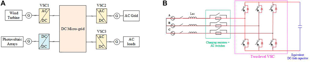
FIGURE 1. Typical schematic of DC micro-grid and the topology of conventional two-level VSC during start-up process. (A) Typical schematic of DC micro-grid; (B) topology of conventional two-level VSC.
At present, in practical DC micro-grid demonstration projects, only one two-level VSC is being used for start-up. With all the other converters blocked, looking from the DC side, these converters can be equivalent to a capacitor (Díaz et al., 2015; Changizian et al., 2022b). As a result, the start-up of the DC micro-grid could be considered as an equivalent capacitor at the DC side charged by the AC sources through a two-level VSC. Depending on the control strategy of the two-level VSC, this start-up process of the DC micro-grid could be divided into two stages (Lin et al., 2018).
In this stage, the common practice is to block all the Insulated Gate Bipolar Transistors and install three-phase charging resistors at the AC side to limit the starting current (Li et al., 2010; Changizian et al., 2022b). The DC-link capacitors are charged to the maximum line-to-line voltage at the AC side through the charging resistors and AC-side inductor. During this period, the starting current is closely related to the circuit parameters, that is, the charging resistance should match the AC-side sources and DC-link capacitance. If it is too small, an overcurrent will be generated inside the converter, causing potential damage to the power electronic components inside the converter or the false trip of the relay protection on the AC side. If it is too big, the duration of the start-up process would be quite long, that is the power supply reliability would deteriorate, especially the system recovery process would be prolonged significantly. In addition, since numerous converters are connected into one DC micro-grid, the number of converters and the equivalent DC-link capacitance are variable, therefore it is impossible to ensure a perfect match between the charging resistance and equivalent capacitance. Furthermore, as for the two three-phase AC switches shown in Figure 1B used for start-up, its closing and open time is in the order of tens or even hundreds of milliseconds, resulting in additional cost and extra start-up time. According to the real project, the start-up time for a micro-grid could be several seconds.
In this stage, the DC voltage slope controllers (Jing et al., 2009a; Song et al., 2010; Tan, 2013; Wang et al., 2016) are used to control IGBTs such that the DC-side voltage increases gradually according to the reference value with controllable charging current, and thus no overcurrent or overvoltage exists during this period.
To limit the starting current of the uncontrolled rectifier stage, different methods have been proposed. In Ned Mohan and William. (2003); Jing et al. (2009b); Hairong et al. (2009), the most appropriate position to install the charging resistors has been investigated, taking into account the location of the DC outlet of the three-phase bridge, AC side of the converter, and AC side of the power grid. In Ke et al. (2011), a universal parameter design method for the charging resistors on the AC side of the converter has been proposed based on Laplace transform. However, it is also hard to adjust the resistance dynamically according to the variable equivalent capacitance for these charging resistors based start-up methods. A DC voltage regulator was used by Changizian et al. (2022b), where the charging speed and starting current could be controlled at any level needed, but it was not practical in an actual project due to the high cost. An alternative method for the conventional start-up is to use SCRs to replace charging resistors. By slowly reducing the firing angle of the SCRs, the starting current could be limited (Dalian dagong andao ship technology Co. and LTD, 2011). However, the rate at which the firing angle decreases has to be reset when the equivalent DC-link capacitance changes. According to the thorough literature review, the existing start-up methods for the first stage are not suitable for the starting converter of a DC micro-grid because of the variable equivalent DC-link capacitance.
To address this problem, an improved two-level VSC with the advantages of DC fault ride-through and soft start-up is proposed in this article. The topology and control sequence of the improved two-level VSC is briefly introduced in Section 2. The theoretical analysis of the starting current is discussed in Section 3. Simulation is carried out for verification in Section 4. In the end, Section 5 concludes this article.
The topology of the improved two-level VSC is illustrated in Figure 2A. Compared with a conventional two-level VSC, a SCR (T1∼T3) and an antiparallel diode (DT1∼DT3) are added in the up-bridge-arm of each phase. Referring to Figure 2A, IGBTs and the corresponding freewheel diodes are indicated by VT1∼VT6 and D1∼D6, respectively. The corresponding control sequence is shown in Figure 2B.
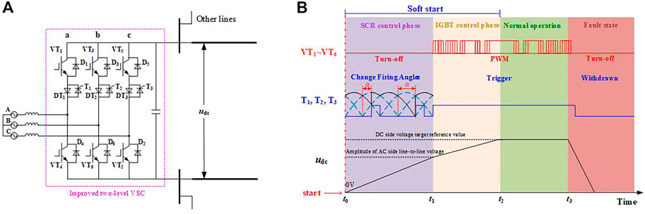
FIGURE 2. Topology and control sequence of the improved VSC. (A) Topology of the improved VSC; (B) control sequence for the improved VSC.
Suppose the start-up process begins at t0. During the start-up process, variable firing angle control is employed in the starting converter, and all the other converters are blocked. Before the DC-side voltage (udc) reaches the amplitude of the AC-side line-to-line voltage (t1), with VT1∼VT6 of the starting converter blocked, udc and the current in the bridge-arm of each phase could be controlled by adjusting the firing angle (α) of T1∼T3 in the range of 0°–180° dynamically. During this period, the ultimate safety current of the diodes and SCRs is taken as the reference value to adjust α of T1∼T3 in each control period. In this way, udc can rise to the amplitude of the AC-side line-to-line voltage at t1 with the maximum allowable current, meaning the start-up time is the shortest. It should be noted that when equivalent capacitance changes, this control method will still be valid, and the starting current could be the invariant by adjusting α of T1∼T3 properly. In this case, the start-up time becomes variable with the equivalent capacitance.
The following is the IGBT control stage (t1∼t2 in Figure 2). Triggering signals are continuously applied on T1∼T3, that is, T1∼T3 are equivalent to the diodes and the improved two-level VSC is equivalent to the conventional two-level VSC. The control signals that are generated by the pulse width modulation (PWM) are sent to VT1∼VT6 to control udc to follow the preset DC-side voltage reference. It should be noted that the slope reference value is employed to prevent excessive starting current in each bridge. When udc is finally stabilized to be the rated DC voltage, the soft start-up process of the improved two-level VSC is completed. After this, all the other converters in the DC micro-grid are unlocked and begin to operate normally.
During the normal operation (t2∼t3 in Figure 2), with T1∼T3 continuously triggered and equivalent to the diodes, the improved two-level VSC is equivalent to the conventional two-level VSC. The constant voltage control mode or constant power control mode is adopted by the corresponding converters connected in the micro-grid.
As for the two-level VSC, with the maximum AC-side line-to-line voltage alternates, the corresponding IGBT and diodes constitute a boost chopper to realize conversion from AC to DC. As a result, udc is higher than the AC-side voltage at any time during the normal operation.
For the DC micro-grid based on the conventional two-level VSC, when a DC fault occurs, the DC-link capacitors discharge rapidly, resulting in the DC voltage collapsing and surge current with high amplitude, a long decay time constant, and no zero-crossing point (Wang et al., 2021). Triggered by the overcurrent, IGBTs are blocked rapidly, leaving the freewheel diodes exposed to the long-lasting overcurrent, which can lead to the damage of the diodes (Islam et al., 2020). Therefore, the conventional two-level VSC lacks DC fault ride-through ability, which has been regarded as a technical bottleneck that limits the wide industry application of the DC micro-grid.
As for the improved VSC, when a DC fault is detected at t3 in Figure 2B, triggered by an overcurrent, turn-off signals are sent to IGBTs, and the triggering signals for SCRs are withdrawn after a short time delay. By adding a small inductor at the DC outlet, udc would drop slowly at the early stage of DC fault. Under the effect of udc, which is larger than the AC-side voltage, the currents in T1∼T3 would drop to zero in a short time. As a result, T1∼T3 can be turned off, and the electrical path from the AC source to fault point can be blocked. In this way, almost no surge current flows through the power electronic components inside the converter, that is, the improved converter has the ability for DC fault ride-through.
As mentioned before, to achieve soft start-up of the improved two-level VSC, on the one hand, the start-up current is expected to be always within an allowable value of power electronic components, while on the other hand, the DC voltage is expected to rise as rapidly as possible to realize rapid start-up. In fact, there is a contradiction between the starting current value and rise rate of the DC-side voltage. Therefore, the ultimate objective of the soft start-up is to maintain the starting current in each bridge-arm close to the allowable value by adjusting α of T1∼T3 dynamically, making the starting current independent of the equivalent capacitance, such that the DC voltage could rise as rapidly as possible.
To provide the theoretical basis for the soft-start control strategy, the theoretical analysis about the maximum, generation mechanism of the starting current, and influencing factors are conducted in this part.
Since DC voltage of the DC micro-grid is established by one starting converter, looking from the DC side, all the other converters are equivalent to capacitors. Therefore, the equivalent circuit in the SCR control stage is shown in Figure 3A, where Lac is the inductor on the AC side and Cdc is the equivalent DC-link capacitor. For a DC micro-grid, due to the small value of the AC-side inductor, at any given time, only an up-bridge-arm connected to the highest voltage and a down-bridge-arm connected to the lowest voltage on the AC side are in the conducting state, that is, the maximum AC-side line-to-line voltage source charges the equivalent capacitor of the DC side. Based on Figure 3A, the on-state power electronic components at different maximum line-to-line voltage are listed in Table 1. As a result, the equivalent circuit can be simplified as shown in Figure 3B, where uac_max is the maximum AC-side line-to-line voltage, T and D indicate the corresponding SCR and diode in Table 1, respectively, and uac is the equivalent AC-side voltage under the effect of the firing angle of SCR.
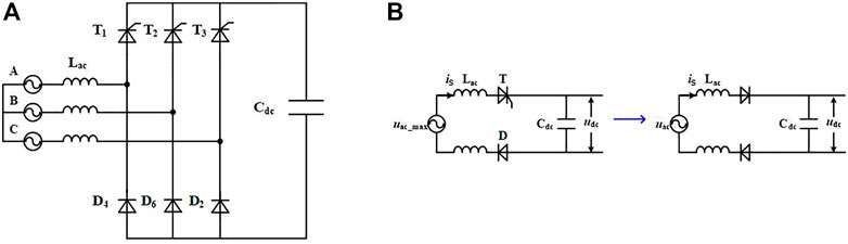
FIGURE 3. Equivalent circuit of the improved VSC in SCR control phase. (A) Equivalent circuit and (B) simplified equivalent circuit.
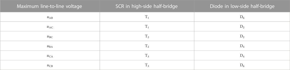
TABLE 1. Power electronic devices in on-state at different maximum line-to-line voltages during SCR control phase.
By changing the firing angle (α) of T1∼T3, the waveform of uac will be changed. When α = 0°, as shown in Figure 4, each SCR is commutated at the natural commutation point and the waveform of uac is the envelope curve of the maximum line-to-line voltage. With the increase of α, the average value of uac gradually deceases and finally drops to 0 when α = 180°. Furthermore, it is also seen that the triggering signal for SCR in phases A, B, and C should differ by 120°. In this way, by adjusting α, the waveform of uac can be changed and then affect the starting current in half-bridges and rising rate of udc. When udc reaches the amplitude of the AC-side line-to-line voltage, no matter how α changes, udc would no longer increase, therefore udc at the end of the SCR control phase would be the maximum AC-side line-to-line voltage.
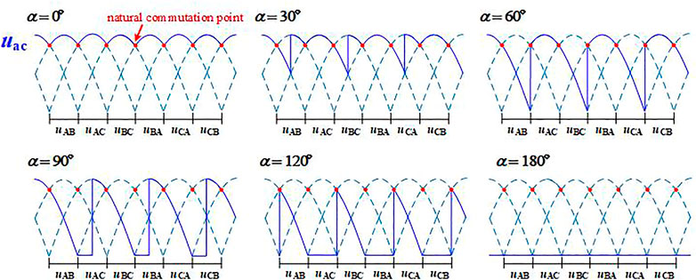
FIGURE 4. Typical waveform of uac at different firing angles of the SCRs in the improved VSC.
During the IGBT control phase, the improved two-level VSC is equivalent to conventional VSC, and the control methods are the same. Therefore, to avoid repetition, details about this period is not discussed in this article.
According to the analysis in Section 3.1, the triggering signal for each SCR differs by 120°, therefore when the rated frequency at the AC side equals 50 Hz, the basic control period of the firing angle α becomes 6.67 ms.
Referring to the simplified equivalent circuit in Figure 3B, the maximum current in each bridge-arm iS and DC-side voltage udc in each basic control period can be calculated based on the equivalent circuit shown in Figure 5, where Lac is the equivalent inductance of each phase at the AC side, and Cdc is the equivalent capacitance at the DC side. Due to the existence of diode seen in Figure 3B, there is no discharge loop for Cdc, therefore udc at the end of each basic control period is the maximum of udc_e as shown in Figure 5, and the maximum of iS is the maximum of iS_e also seen in Figure 5.
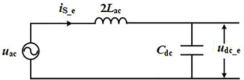
FIGURE 5. Equivalent circuit for the calculation of iS and udc in each basic control period.
Referring to Figure 5, the differential equation with udc_e and iS_e as the variables is
The corresponding state equation can be derived as follows:
During a certain basic control period, the initial value of iS_e is 0. As a result, at a certain α and an initial value of udc_e, the numerical solutions of udc_e and iS_e during each control period is obtained by solving the above stated equation with the Runge–Kutta method.
The numerical solution cannot clearly indicate the relationship between the control variable (α) and controlled variable (iS), therefore a qualitative analysis is conducted in this part. According to Figure 3B, in a control period, based on the Kirchhoff’s Voltage Law, the following equation is satisfied:
Bu integrating both the sides of this equation over time,
Taking α = 90° as an example, the waveforms of uac and udc are shown in Figure 6. In the control period shown in Figure 6, iS reaches its maximum at the red dot, and its peak value is determined by the area of the shaded part enclosed by udc and uac. As a result, when iS exceeds the reference value, by increasing α in the next control phase, the area enclosed by udc and uac would be reduced, and thus the maximum of iS in the next control would be reduced. Similarly, when iS is lower than the reference value, by decreasing α in the next control phase, the maximum of iS in the next control would be increased. In this way, the maximum of iS in each control period could be maintained around the reference value to charge the equivalent DC-link capacitor rapidly.
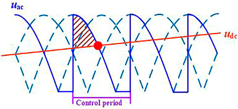
FIGURE 6. Typical waveforms of uac and udc when α = 90°.
Based on the above analysis, a dynamic control strategy of the firing angle (α) is proposed with the goal of maintaining the maximum for the current in the bridge-arm close to the reference value, such that udc could rise up to the maximum AC-side line-to-line voltage as soon as possible without causing any overcurrent.
The flow chart of the control strategy is shown in Figure 7. In every control period, the maximum of the bridge-arm current is measured and compared with the reference value to calculate the control error, which is then used as the input for the PI controller to calculate the reference value of α for the next control period. When udc reaches the amplitude of the AC-side line-to-line voltage, the SCR control phase is completed.
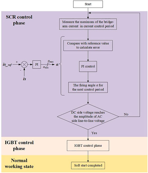
FIGURE 7. Flow chart of the dynamic control strategy of firing angle.
To verify the proposed soft-start control method, a simplified typical DC micro-grid model, as shown in Figure 8, is established in PSCAD/EMTDC, the parameters of which are listed in Table 2 (Salomonsson et al., 2009). In the simulation model, VSC1 is set as the starting converter. According to the analysis before, in the start-up process of the two-level VSC, the current in each bridge-arm and the duration of the start-up process should be limited. Therefore, the maximum of the current iac and the duration of the start-up are used to evaluate the effectiveness of the proposed soft start-up method in this part.
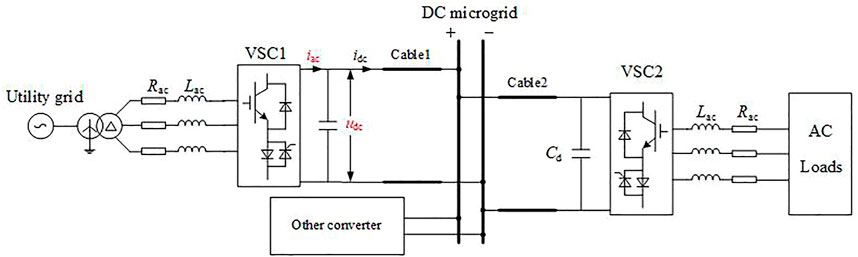
FIGURE 8. Simplified typical DC micro-grid model.
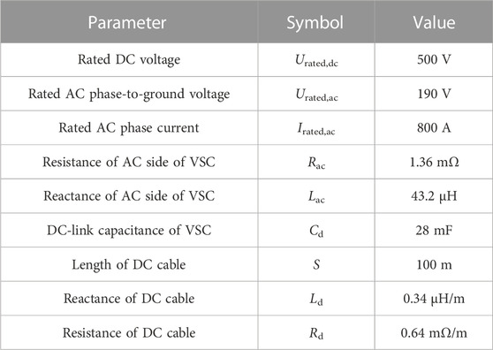
TABLE 2. Parameters of simplified typical DC micro-grid.
In simulation, the soft start-up process begins at 0 s, taking the rated current of the AC side as the reference value for the maximum current in each bridge-arm in the SCR control phase, which is 800 A. Once the DC-side voltage udc reaches the amplitude of the AC-side line-to-line voltage (∼465 V), triggering signals are continuously applied to the SCRs. By controlling IGBTs with PWM, udc rises up gradually to the rated DC voltage (500 V) in 0.1 s.
The simulation results of udc and iac are shown in Figure 9. As shown in Figure 9, at the early stage of the SCR control phase (t < 0.25 s), due to the small value of udc, by controlling the firing angle α for SCRs, the maximum bridge-arm current in each basic control period can be maintained at approximately 800 A. After 0.25 s, as udc rises, the current in each bridge-arm gradually decreases and eventually drops to 0 with udc reaching the maximum AC-side line-to-line voltage at 0.42 s. After this, the soft-start process enters the IGBT control stage, and udc follows the slope reference value to the rated DC voltage at 0.52 s. As a result, during the whole start-up process, there is no overcurrent (>800 A) in each bridge-arm, and udc can reach the rated DC voltage within 0.52 s. The simulation results are consistent with the theoretical analysis in Section 3.
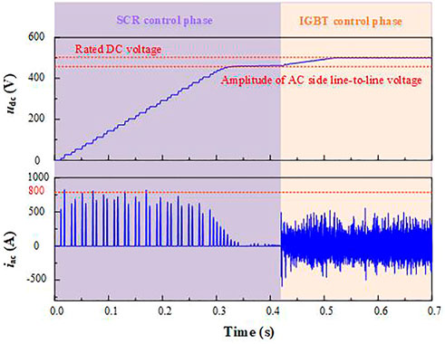
FIGURE 9. Simulation results of udc and iac using the proposed soft start-up method.
To present the advantages of the proposed soft start-up method, comparisons between the proposed soft start-up method and conventional start-up method that have been mentioned in Section 1 are conducted in this part. As for the conventional method, the starting resistance is set as 0.2 Ω in the typical DC micro-grid, and the operation time of the AC switch is set to be 0.1 s.
The simulation results of udc and iac using the conventional start-up method is shown in Figure 10. As shown in Figure 10, the start-up process begins at time 0. At first, it takes 0.1 s to switch the starting resistors to the AC side. Then, the equivalent DC-link capacitor is charged by a three-phase AC source through the uncontrolled rectifier circuit. Due to the small value of the charging resistor, iac with the peak value of 1,250 A exceeds the rated AC phase current significantly. When udc reaches the amplitude of the AC-side line-to-line voltage at 0.33 s, it takes another 0.1 s for AC circuit breaker to close so that the charging resistors are bypassed. In this case, the whole duration of the start-up process using the conventional starting method is 0.53 s. Compared with the proposed soft start-up method, the starting time is the same, but the starting current using the conventional starting method is uncontrollable and exceeds the limit significantly. Increasing the value of the starting resistor is a method to solve this problem, but the duration of the start-up process will be prolonged.
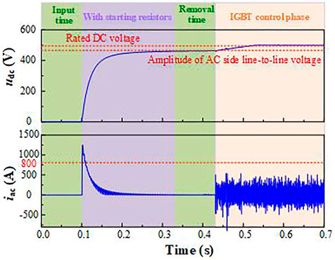
FIGURE 10. Simulation results of udc and iac using conventional start-up method.
More importantly, as the number of equivalent DC-link capacitors of converters (Cdc in Figure 4) in the DC micro-grid is variable, the charging resistance should be adjusted dynamically according to Cdc. Since idc and udc in the start-up process using the conventional start-up method are only dependent on the circuit parameters before the IGBT control phase, the maximum of idc will increase with the increase of Cdc, thus the starting resistor with a bigger value is required. By calculating numerally, the relationship between Cdc and the charging resistance has to limit the maximum of iac within the rated AC phase current, as illustrated in Figure 11. As shown in Figure 11, when Cdc is 140 mF in the DC micro-grid during the start-up process, a starting resistance of more than 0.33 Ω is required to avoid overcurrent inside the starting converter, while the increased starting resistance would extend the duration of the start-up process to 0.88 s when Cdc is 56 mF.
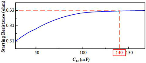
FIGURE 11. Relationship between Cdc and charging resistance.
Based on the above analysis, as for the conventional start-up method, there is a contradiction between the start-up speed and starting current. Therefore, it is almost impossible to adjust the charging resistor dynamically according to the variable Cdc without causing any overcurrent.
However, as for the proposed soft start-up method, udc can always increase at the fastest possible speed, regardless of the equivalent capacitance of the DC micro-grid.
As mentioned previously, besides the ability of the soft start-up, the improved two-level VSC is also capable of DC fault ride-through.
In the simulation model shown in Figure 12, taking VSC1 as an example, an inductor with a value of 20 μH is installed at the DC outlet. A DC pole-to-pole fault occurs at t = 1s, and after a fault detection time of 1 ms, the fault is detected. At this point, turn-off signals are sent to VT1∼VT6, and triggering signals for T1∼T3 are withdrawn after 400 μs. The simulation results are shown in Figure 12. As shown in Figure 12A, after the DC fault occurs, with the effect of the inductor installed at the DC outlet when the fault is detected, the DC-side voltage is still bigger than the amplitude of the AC-side line-to-line voltage. As a result, fault currents inside the converter are eliminated in 0.623 ms, and there is no overcurrent inside the improved two-level VSC.
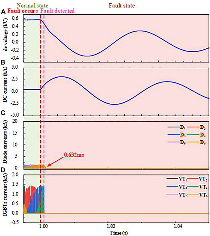
FIGURE 12. Simulation results of the improved VSC during DC fault ride-through. (A) DC-side voltage; (B) DC-side current; (C) currents in D1∼D6 and T1∼T3; and (D) currents in VT1∼VT6.
As for the conventional two-level VSC, because of the lack of DC fault ride-through capability, there will be a long-lasting overcurrent in the freewheel diodes when DC fault occurs. The simulation results of the conventional two-level VSC during the same DC fault are shown in Figure 13. When the fault is detected, turn-off signals are sent to IGBTs immediately, leaving the freewheel diodes subjected to an overcurrent, which is up to eight times the current during a normal operation and can lead to permanent damage.
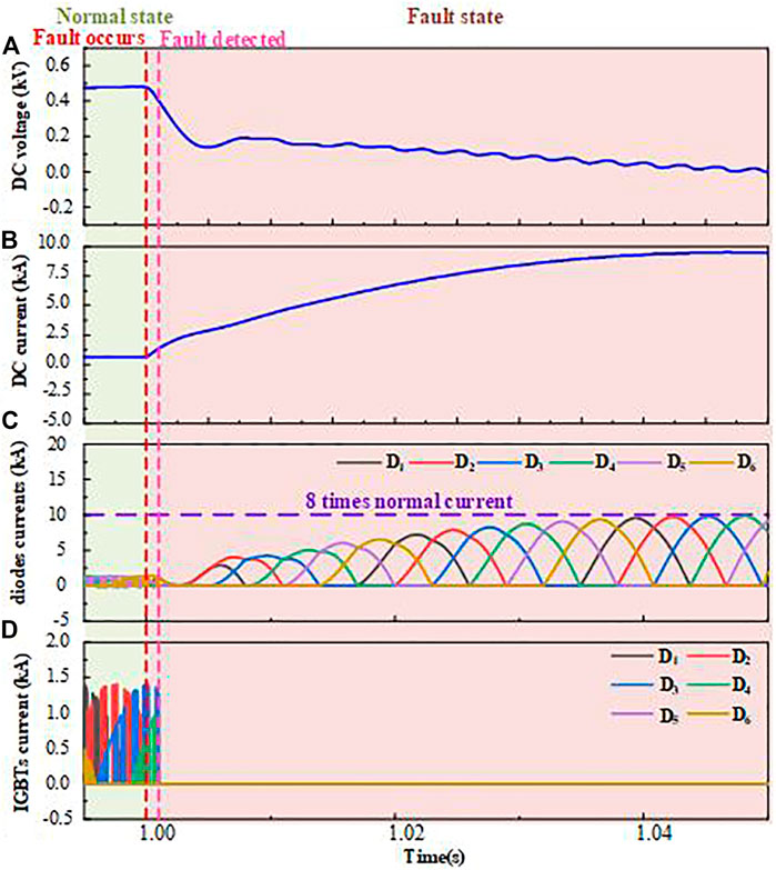
FIGURE 13. Simulation results of the conventional VSC during DC fault ride-through. (A) DC-side voltage; (B) DC-side current; (C) currents in D1∼D6 and T1∼T3; and (D) currents in VT1∼VT6.
According to the above analysis, when compared with the conventional two-level VSC and start-up method, the improved VSC can achieve flexible starting current control without depending on the DC micro-grid parameters with the proposed soft start-up method and have DC fault ride-through capability.
Due to the vulnerability of the power electronic components inside the DC micro-grid, the surge current caused by charging the DC-link capacitors during the start-up process should be limited. The conventional start-up method for the DC micro-grid is based on the three-phase charging resistors on the AC side which lack controllability, thus it is hard to balance the start-up speed and the value of the starting current. Aiming at this problem, an improved two-level VSC with a module of an SCR and anti-parallel diode in each up-bridge-arm is proposed in this article. By controlling the firing angles of the SCRs with a dynamic control strategy, not only can the starting current be limited to a given value but also can the fast start-up of the DC micro-grid be realized. Moreover, by rapidly turning off all the SCRs after DC faults, the fault currents in the improved VSC can be eliminated, which means it has DC fault ride-through capability. The topology and control sequence of the improved two-level VSC are introduced. The relationship between the transient starting current and firing angles of the SCRs inside the improved VSC is analyzed both quantitatively and qualitatively based on the equivalent circuit during the start-up process. According to the theoretical analysis, a dynamic control strategy of the firing angle is proposed with the goal of maintaining the maximum current in the bridge-arm close to its limits so as to achieve rapid start-up without causing any overcurrent. In the end, a simplified typical DC micro-grid model is established in PSCAD/EMTDC for verification. The results show that for the conventional start-up method based on the charging resistors, the start-up time is long, and the starting current may exceed a given value with the change of grid parameters. For the proposed start-up method in this article, the start-up current can always be controlled to a given value to achieve rapid start-up without depending on the grid parameters. The proposed start-up method can shorten the start-up time and make the starting current controllable to significantly reduce the risk of damage to power electronic components, thus having the guiding significance for future constructions of the DC micro-grid.
The original contributions presented in the study are included in the article/Supplementary Material; further inquiries can be directed to the corresponding authors.
Conceptualization: WW, RL, and BTL; methodology: WW, RL, and HC; software: RL and JY; validation: WW; writing—original draft preparation: WW and RL; writing—review and editing: RL and BL; supervision: BL and MP; project administration: BL and MP. All authors have read and agreed to the published version of the manuscript.
This research was funded by Open Fund of State Key Laboratory of Power Grid Safety and Energy Conservation, grant number JBB51202201500 and the National Natural Science Foundation of China, grant number 51907141.
The authors declare that the research was conducted in the absence of any commercial or financial relationships that could be construed as a potential conflict of interest.
All claims expressed in this article are solely those of the authors and do not necessarily represent those of their affiliated organizations, or those of the publisher, editors, and reviewers. Any product that may be evaluated in this article, or claim that may be made by its manufacturer, is not guaranteed or endorsed by the publisher.
Changizian, M., Mizani, A. R., and Shoulaie, A. (2022). Proposed a new Voltage rebalancing method for pole-to-ground fault in bipolar two level VSC-HVDC. IEEE Trans. Ind. Electron. 69 (3), 2157–2165. doi:10.1109/TIE.2021.3068668
Changizian, M., Mizani, A., and Shoulaie, A. (2022). A novel control method for restraining starting-up overcurrent in VSC-HVDC System. Electr. Power Syst. Res. 206, 107816–107911. doi:10.1016/j.epsr.2022.107816
Chengyong, Z., and Ying, S. (2006). “Study on control strategies to improve the stabilityof multi-infeed HVDC systems applying VSC-HVDC,” in Proc. Int. Conf. On electrical and computer engineering (Ottawa, Canada.
Dalian dagong andao ship technology Co., LTD (2011). A three-phase pulse width modulation (PWM) rectifier soft starting system. Available at: http://www.innojoy.com/patent/patent.html?docno=CN201110180400.1&pnmno=CN102255486A&trsdb=fmzl&showList=true (Accessed August 27, 2022).
Díaz, E. R., Su, X., Mehdi, S., Juan, C. V., Han, M., Guerrero, J. M., et al. (2015). “Intelligent DC Microgrid living Laboratories - a Chinese-Danish cooperation project,” in Proc. 2015 IEEE 1st int. Conf. DC microgrids (Atlanta, GA, USA: IEEE).
Dragicevic, T., Vasquez, J. C., Guerrero, J. M., and Skrlec, D. (2014). Advanced lvdc electrical power architectures and microgrids: A step toward a new generation of power distribution networks. IEEE Electrific. Mag. 2, 54–65. doi:10.1109/mele.2013.2297033
Georgios, S., and Massimo, B. (2016). Stability analysis of two-terminal VSC-HVDCsystem using the Net-damping criterion. IEEE Trans. Power Deliv. 31 (4), 1748–1756.
Hairong, C., Jing, Z., and Wulue, P. (2009). Start-up control of VSC based on HVDC system. High. Volt. Eng. 35 (5), 1164–1169.
Hatziargyriou, N. (2008). Microgrids [guest editorial]. IEEE Power Energy Mag. 6 (3), 26–29. doi:10.1109/mpe.2008.920383
Islam, S., Anju, M., Anand, S., and Sahoo, S. R. (2020). “Determination of fault clearing time based on thermal limits of power semiconductor devices in DC microgrids,” in Proc. 2020 11th int. Symp. Power electron. Distrib. Gener. Syst. (PEDG) (Dubrovnik, Croatia: IEEE).
Jing, Z., Xu, Z., and Chen, H. (2009). Startup procedure for the VSC-HVDC system. Trans. China Electrotech. Soc. 24 (9), 159–165.
Jing, Z., Zheng, X., and Hairong, C. (2009). Startup procedures for the VSC-HVDC system. Trans. China Electrotech. Soc. 24 (9), 159–165.
Kakigano, H., Miura, Y., and Ise, T. (2010). Low-voltage bipolar-type DC microgrid for super high quality distribution. IEEE Trans. Power Electron. 25 (12), 3066–3075. doi:10.1109/tpel.2010.2077682
Ke, W., Jian, L., and Shengchun, Y. (2011). Startup procedures for the VSC-HVDC system supplying power to passive network. Proc. CSEE. 31 (1), 277–281.
Li, G., Zhao, C., Zhang, X., Li, G., and Zhao, C. (2007). “Research on "Soft Start-up" of VSC-HVDC in power system restoration after blackouts,” in 2nd IEEE conf. Ind. Electron (Harbin, China: IEEE).
Li, L., Zhou, M., Li, S., and Li, Y. (2010). “A new method of black start based on VSC-hvdc,” in 2010 international conference on computing, control and industrial engineering (Wuhan, China. doi:10.1109/CCIE.2010.83
Lin, S., Wang, L., Mu, D., Liu, L., Liao, K., and He, Z. (2018). Research on starting up control strategy of VSC-HVDC system. IET Renew. Power Gener. 12 (16), 1957–1965. doi:10.1049/iet-rpg.2018.5422
Liu, Y., Zhou, Y., Wu, Y., Yuan, Y., Kong, M., Jie, Y., et al. (2019). “A Study on VSC- HVDC based black start method,” in 4th IEEE workshop on the electronic grid (eGRID) (Xiamen, China: IEEE).
Mattsson, I., Railing, B. D., and Williams, B. (2004). “Murraylink, the longest underground HVDC cable in the world,” in Cigre session, B4–B103.
Ned Mohan, T. M. U., and William, P. R. (2003). “Line-Frequency ac uncontrolled dc,” in Power electronics: Converter, applications, and design (New York: John wiley and sons Press).
Railing, B. D., Moreau, G., and Ronstrom, L. (2004). “Cross sound cable project second generation VSC technology for HVDC,” in Cigre session, B4–B102.
Salomonsson, D., Soder, L., and Sannino, A. (2009). Protection of low-voltage DC microgrids. IEEE Trans. Power Del. 24, 1045–1053. doi:10.1109/tpwrd.2009.2016622
Singh, V. K., Suryakiran, B. V., Verma, A., and Bhatti, T. S. (2021). Modelling of a renewable energy-based AC interconnected rural microgrid system for the provision of uninterrupted power supply. IET Energ. Syst. Integr. 3 (2), 172–183. doi:10.1049/esi2.12015
Song, W., Li, G., Zhou, M., and Zhe, Z. (2010). “Research on soft regulation strategy of VSC-HVDC systems,” in IEEE PES general meeting (Providence, RI: IEEE).
Sreedhar Kumar, K., and Chandra Sekhar, J. N. (2015). Limitation of fault currents by positioning of superconducting fault current limiter in AC and DC microgrid. IEEE Trans. Power Deliv. 4 (2), 901–907. doi:10.15662/ijareeie.2015.0402042
Sumanth, , Akash, S., and Modi, S. (2020). Fault analysis and protection of DC microgrid. Int. J. Eng. Technol. 8, 122–126. doi:10.17577/IJERTCONV8IS11028
Tan, L. (2013). Startup schemes for convert station of MMC-HVDC system applied in grid black start. Automa. Electr. Power Syst. 37 (9), 117–122.
Wang, P., Zhang, X. P., Coventry, P. F., and Zhang, R. (2016). Start-up control of an offshore integrated MMC multi-terminal HVDC system with reduced DC voltage. IEEE Trans. Power Syst. 31, 2740–2751. doi:10.1109/tpwrs.2015.2466600
Wang, W., Wang, L., He, Z., Xin, Y., and Li, G. (2021). A multiport superconducting fault-current-limiting circuit breaker for a flexible DC power grid. IET Energ. Syst. Integr. 3 (3), 306–316. doi:10.1049/esi2.12032
Keywords: DC micro-gird, AC-DC converter, start-up, topology, control method
Citation: Wen W, Lyu R, Li B, Cao H, Yu J, Li B and Popov M (2023) A soft start-up method for DC micro-grid based on improved two-level VSC with DC fault ride-through capability. Front. Energy Res. 11:1079099. doi: 10.3389/fenrg.2023.1079099
Received: 25 October 2022; Accepted: 20 March 2023;
Published: 31 March 2023.
Edited by:
Pengfeng Lin, Nanyang Technological University, SingaporeReviewed by:
Narottam Das, Central Queensland University, AustraliaCopyright © 2023 Wen, Lyu, Li, Cao, Yu, Li and Popov. This is an open-access article distributed under the terms of the Creative Commons Attribution License (CC BY). The use, distribution or reproduction in other forums is permitted, provided the original author(s) and the copyright owner(s) are credited and that the original publication in this journal is cited, in accordance with accepted academic practice. No use, distribution or reproduction is permitted which does not comply with these terms.
*Correspondence: Rui Lyu, cmF5bHl1OThAaG90bWFpbC5jb20=; Botong Li, bGlib3RvbmdAdGp1LmVkdS5jbg==
Disclaimer: All claims expressed in this article are solely those of the authors and do not necessarily represent those of their affiliated organizations, or those of the publisher, the editors and the reviewers. Any product that may be evaluated in this article or claim that may be made by its manufacturer is not guaranteed or endorsed by the publisher.
Research integrity at Frontiers
Learn more about the work of our research integrity team to safeguard the quality of each article we publish.