
95% of researchers rate our articles as excellent or good
Learn more about the work of our research integrity team to safeguard the quality of each article we publish.
Find out more
ORIGINAL RESEARCH article
Front. Energy Res. , 09 February 2023
Sec. Process and Energy Systems Engineering
Volume 11 - 2023 | https://doi.org/10.3389/fenrg.2023.1064067
This article is part of the Research Topic Role of Mathematical Modeling in Advanced Power Generation Systems View all 10 articles
The film condensation of steam is very common in several industrial areas, such as condensers in power plants, seawater desalination, and air-conditioning systems. In some studies, the non-condensable gas and liquid film are overlooked for the sake of simplicity. To provide an integral computational scheme, in the present study, the film condensation of steam in the presence of non-condensable gas on a vertical plate has been simulated using a two-dimensional CFD model combining a wall condensation model and volume of fluid (VOF) model. After verification, the proposed computational scheme is used to simulate the steam condensation process, with the mass fractions of non-condensable gas varying from 5% to 45%. The results indicate that the concentration of non-condensable gas in the boundary layer decreases gradually with the condensation process, resulting in a decline in the synergy between temperature and velocity field. It can also be found that the fluctuation of the liquid film can influence the concentration distribution of the non-condensable gas layer. For cases with high concentrations of steam, the thermal resistance of liquid film can reach more than 20% of the total thermal resistance, which should not be ignored.
Film condensation is a common heat transfer phenomenon in many industrial domains, such as condensers in thermal or nuclear power plants, seawater desalination, and air-conditioning systems. In these applications, the steam often contains non-condensable gas, which significantly reduces the heat transfer rate due to the diffusion resistance generated by the gas-vapor boundary layer (Minkowycz and Sparrow, 1966). In addition, the existence of non-condensable gases increases the complexity of heat and mass transfer in the film condensation process, especially near the phase interface (Rao et al., 2008; Zhou et al., 2010; Krishna and Rao, 2017; Wang et al., 2022). Therefore, it is necessary to study the condensation mechanism in the presence of a non-condensable gas further to develop the heat transfer theory and guide its practical applications.
Many researchers have tried to establish a theoretical analysis method to solve film condensation issues with non-condensable gas using the boundary layer theory. For example, Rose (1980) employed an approximate equation based on the uniform-property boundary-layer theory to calculate the transfer rate of steam on the condensate surface in the presence of non-condensable gas. Liao et al. (2009) proposed an analysis method based on a two-phase boundary layer to analyze the condensation of a steam-gas mixture on a vertical plate, and the effects of superimposed forced convection on natural convection in steam-gas flow were investigated. In addition, they also argued that the bulk flow blowing capability can be defined by a conventional mass transfer driving potential. Other related schemes can also be found in the literature, such as the double film theory (Lewis and Whitman, 1924; Colburn and Hougen, 1934), the diffusion layer theory (Peterson et al., 1993), and the heat and mass transfer analogy theory (Sparrow and Lin, 1964). The theoretical analysis relies on a lumped parameter that usually determines the average heat transfer coefficient at the condensing wall by empirical correlation or by solving the simplified boundary-layer equation without detailed information inside the film. Another popular approach to predicting the condensation process is using empirical or semi-empirical correlations. However, the main obstacle is that most correlations are not universally valid (Kharangate and Mudawar, 2017).
In the experimental aspect, the main research directions focus on the heat transfer characteristics of film condensation under different working conditions and the heat transfer enhancement by variant surface properties (Anderson et al., 1998; Ahn et al., 2022). Al-Diwany and Rose (1973) studied the condensation of an air, argon, nitrogen, and water vapor mixture on a vertical plate under natural convection, and the experimental results are in good agreement with the theoretical solution. Chung et al. (2004) measured the heat transfer rates of steam-air condensation on a vertical plate under forced convection and found that small mixture flows can obviously enhance heat transfers. To further improve the heat transfer efficiency, Wang et al. (2013) proposed a new type of left-right symmetric internally finned tube and confirmed that this design can reduce the thickness of the non-condensable gas layer and enhance the steam condensation. Yi et al. (2016) experimentally investigated the condensation process of an air-steam mixture on an isothermal vertical plate. Four typical condensation modes were observed: drop, drop-streak, film, and streamlet. However, no strict boundaries among these condensation modes were recognized because different modes can coexist under the same experimental condition.
Recently, a numerical calculation has become an important means to solve condensation problems, as it can provide more detailed data compared with experimental methods (e.g., Hammoudi et al., 2018; Feurhuber et al., 2019; Zhang et al., 2019; Kleiner et al., 2020). In the simulation of the condensation process, a key issue is how to implement mass transfer between two phases, which is the phase change method. The Lee model (Lee, 1980), based on the hypothesis of mass transfer at constant pressure in a quasi-thermo-equilibrium state, is the most widely used model for simulating phase problems, especially condensation. Using the finite volume method, Siow et al. (2007) presented a two-phase model to analyze laminar film condensation of vapor with non-condensable gas in declining parallel-plate channels. Tang et al. (2012) solved the heat and mass transfer problem of steam-air mixture condensation outside a smooth horizontal tube with the finite difference method and a double boundary layer model. They observed that the mass concentration and velocity of the non-condensable gas increased from the bulk mixture to the interface. According to the operating conditions, the mass transfer intensity factor is a key empirical coefficient with a wide range in this model (e.g., Alizadehdakhel et al., 2010; Liu et al., 2012; Riva and Col, 2012; Qiu et al., 2014; Lee et al., 2015; Kharangate et al., 2016). More than that, the mass transfer coefficient is usually treated as a constant, which is not physical in the continuous phase change of condensation. In recent years, the wall condensation model (WCM) has been used to study the condensation of steam in the presence of a non-condensable gas. This model calculates the mass flux of steam from Fick’s law of diffusion, and the steam concentration near the wall is obtained from its partial pressure at its saturation temperature, which is based on the condensing wall temperature (e.g., Li, 2013; Zschaeck et al., 2014; Punetha and Khandekar, 2017; Kumar et al., 2021). However, in WCM, the liquid boundary layer is neglected during simulations.
Actually, the characteristics of both the non-condensable gas layer and the liquid film shape evolved in the condensation process. The wave motion can be observed when the local Reynolds number of the liquid film is greater than 30 (Bejan, 1995), which has a great influence on the heat transfer (Lee et al., 2015; Choi et al., 2020). Wang et al. (2016) confirmed that the wave structure can enhance the condensation rate by up to ten percent and that the wave effects on film condensation should be included in the heat transfer analysis. Therefore, an accurate numerical calculation considering the gas-liquid phase interface in the presence of non-condensable gas is necessary, which is close to the actual physical process. In an attempt to solve the above problem, a new computational scheme combining WCM and the volume of fluid (VOF) method is implemented in the present study to investigate the change laws of the liquid film shapes and the heat transfer characteristics under different air concentrations and surface subcooling. The simulation results are validated by experimental data reported in the literature, implying that the new scheme can aid in the study of physical mechanisms and influence factors of condensation in the presence of non-condensable gases.
In this study, steam and air are chosen as condensation vapor and non-condensable gas, respectively. When the temperature of the wall is lower than the saturation temperature of steam, a liquid film and a non-condensable gas layer are formed during the condensation process.
Figure 1A illustrates the basis of WCM, which usually ignores the existence of condensing liquid film. Considering that the thermal resistance of the liquid film is neglected, this model overpredicts the rate of condensation when the concentration of non-condensable gas is less than 6% (Punetha and Khandekar, 2017). In addition, the interface wave motion and temperature difference between the interface and wall are not discussed, which is inconsistent with the actual condensation process. In order to increase the accuracy of the simulation results, the WCM and VOF models (Figure 1B) are combined in this study to capture the gas-liquid phase interface. A detailed introduction to this model can be found in Sections 2.4 and 2.5. The liquid film thermal resistance and non-condensable gas layer thermal resistance are both considered in this model. Note that the following assumptions are applied in this study: 1) non-condensable gas is insoluble in the liquid film; 2) the steam saturation pressure and temperature are corresponding to the partial pressure of steam in the cells of the gas-liquid interface; 3) momentum transfer caused by condensation at the gas-liquid interface is neglected; and 4) radiation heat transfer is neglected. The condensation wall is assumed to be initially dry, and the liquid film is generated in the condensation process.
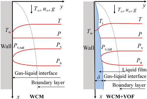
FIGURE 1. Condensation of the steam-air mixture flowing along an isothermal vertical plate: (left) simplified model (adapted from Zschaeck et al., 2014); (right) the model used in this paper.
The VOF method is based on the assumption that the two phases do not merge. The volume fraction α is the ratio of one fluid volume to the whole volume in a cell, which is also solved in the calculation to obtain the distribution of different phases in the computational domain. The volume fractions of different phases in each cell satisfy Eq. 1:
The mass or continuity equation for phase i can be written as:
where Sm is the mass source term, which is depicted in Section 2.4.
The conservation of momentum is
In this equation, p is the pressure shared by all phases. The addition of surface tension to the VOF calculation results in a source term in the momentum equation, based on the continuum surface force model built-in to ANSYS Fluent, which was proposed by Brackbill et al. (1992). The force generated by surface tension gets balanced by the pressure gradient force across the interface. The pressure drop on the gas-liquid interface can be given by:
in which σ is the liquid surface tension coefficient and κ is the interface curvature, which is calculated as follows:
where α is the volume fraction.
The conservation of energy is given by:
where the energy E in the VOF model is calculated by Eq. 7 and hi is the specific enthalpy of phase i
The species conservation equation takes the general form as follows:
where
where Di is the mass diffusion coefficient for species i in the mixture and DT,i denotes the thermal diffusion coefficient. The value of the mass diffusion coefficient is related to pressure, temperature, and the composition of the gas mixture. For binary gas mixtures at low pressure, Di is inversely proportional to pressure and increases with rising temperature, but has the same value for the two components in the mixture (Fuller et al., 1966).
At the gas-liquid interface, the total mass flow of steam in one cell equals the sum of the mass flow from diffusion and convection, which is defined as follows:
Therefore, the following equation to calculate the mass condensation rate can be obtained (Dehbi et al., 2013):
The gradient of the steam mass fraction in the y direction is calculated as follows:
where l represents the distance from the center of the cell to the wall, and Yv,sat is the saturated mass fraction of steam corresponding to the temperature of condensing surface.
The mass of steam condensed per unit volume near the wall is calculated as:
in which
where hfg stands for the latent heat of vaporization.
To obtain the shapes of the liquid film, the physical parameters of mixtures and liquid film at the gas-liquid phase interface need to be calculated accurately. The WCM is improved in this study, and the VOF model is used to capture the gas-liquid interface. The concentrations of steam and air near the gas-liquid interface are calculated by a species transport model. User-defined functions (UDF) are used to read variables and add source terms in a fluid solver. The schematic diagram of the computing program is provided in Figure 2, which is realized by ANSYS Fluent, and the numerical procedure is described in detail as follows.
Step 1. The boundary conditions, like the variables of mixture and wall temperature, are initialized. The steam saturation pressure and temperature values adjacent to the film are calculated in the UDF codes.
Step 2. The meshes in the first layer adjacent to the wall are considered to obtain the volume fraction in each mesh and capture the phase interface. If the condensation criterion is met, the source terms in each mesh are added.
Step 3. Other meshes in the computational domain are treated after Step 2 with the same method, and then a complete cycle is completed.
Step 4. In the subsequent calculation phase, Steps 2 and 3 are repeated so that the phase interface is developed step by step. The different shapes of the liquid film and other information at different stages of condensation can also be obtained.
The geometric computational domain used in this study is given in Figure 3. The length of the wall is 100 mm, and the width of the inlet and outlet measures 30 mm. The steam-air gas mixture enters from the inlet, and steam condenses on the wall. The entire computational domain is divided by a quadrilateral structural mesh. In this study, the two-phase flow near the phase interface is complex, so the mesh elements are refined near the wall to achieve high accuracy.
The inlet boundary condition of the steam-air mixture is the velocity at the inlet boundary, which is fixed at 1 m s-1, except in some cases for validation, and the temperature is 373.15 K. The influent mixture contains different mass fractions of air, varying from 0.05 to 0.45. Pressure outlet boundary is set for the outlet with atmospheric pressure. For the condensation wall, a constant temperature is specified according to the operating conditions. The right side of the model is confirmed as the symmetry boundary condition. The properties of the steam and air, such as the viscosities, thermal conductivities, and specific heat capacities, are assumed to be constants during the simulation. Other thermal properties, like latent heat and saturation pressure, are defined as functions of temperature. At the initial time, the computational domain is full of air, and there is no liquid phase on the wall.
Due to the fact that the thickness of the liquid film, the mass fraction of steam, and the amount of air are always changing with time, a transient solver is chosen in this simulation with the PISO Pressure-Velocity coupling scheme. Through the time step independence check, each time step is set to 0.005 s, and the maximum iteration number in each of them is 80. Convergence is achieved when the volume of liquid on the wall and the mass fraction of air in the outlet reach a constant value. Meanwhile, the residual of the energy equation should be below 10–7 and the residuals of other equations should be below 10–4. More details about working conditions can be found in Table 1.
To check the independence of the grid, three models with 41101, 60501, and 100651 mesh elements have been tested. The mass fraction of steam in the outlet at 0.75 s in Case 4 and Case 1 is shown in Figure 4. With the increase in grid number, the differences in the results are negligible, so we chose the mesh with 60501 elements in the following cases for a balance between accuracy and computational load.
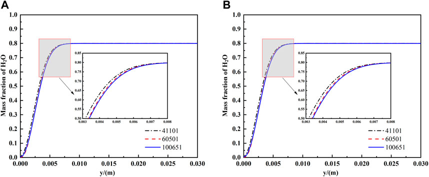
FIGURE 4. Grid independence check with the mass fraction of water vapor in the outlet at 0.75 s: (A) Case 4; (B) Case 1.
The heat transfer rates in this study were compared with the results obtained in the experimental research of Yi et al. (2016) and the analytical solution of Denny et al. (1971) under the same working conditions. The overall trend of the numerical simulation results is the same as the experimental values, as shown in Figure 5. The average heat transfer coefficients decrease with the increase in air bulk concentration and increase with the decrease in subcooling. In Figure 6, the ratio of heat flux to that from Nusselt’s model obtained in our simulation was compared with the results from Denny et al. (1971). Both results show that the influence of non-condensing gas on the heat flux in vertical plates increases with mixture gas flow direction. The average deviation is less than 25% in the data shown in Figures 5, 6, indicating that this simulation model is reliable.
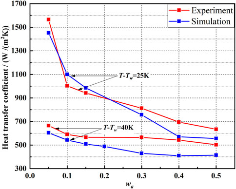
FIGURE 5. Comparison of the average heat transfer coefficients obtained in our simulation and Yi’s experiment (ug = 1 m/s).
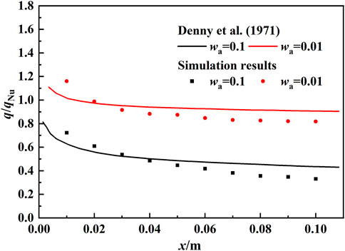
FIGURE 6. Ratio of heat flux to that from Nusselt’s model obtained in our simulation and the analytical solution of Denny et al. (1971) (ug = 3.04 m/s, T-Tw = 22.23 K).
It should be noted that the heat transfer coefficients obtained in this study are lower than the experimental values, especially when the subcooling is 40 K. In our simulation, the computational domain is initialized to be full of air under the same conditions. When the mixture gas flows in the computational domain, some of the existing air in the computational domain is trapped due to the viscous effect, and thus the content of non-condensable gas near the wall slightly increases, which may lead to lower average heat transfer coefficients. On the other hand, the shape of the liquid film obtained through numerical simulation is film condensation. In the experiments, however, the average heat transfer coefficients are obtained under various condensation forms, including drop, drop-streak, streamlet, and film-like condensation, which may lead to the deviation between simulation and experimental results.
As the steam-air mixture flows along the vertical wall, the steam begins to condense due to the subcooling, the solid surface is covered by the condensate water, and the liquid film forms on the wall. At the same time, a high-concentration non-condensable gas layer is formed on the surface of the liquid film. The change in air mass fraction and the thickness of the liquid film in the computational region can be seen in Figure 7. With the aggregation of the condensate, the liquid film becomes thicker. Along with the mass and heat transfer near the gas-liquid interface, the mass fraction of steam and air varies with the phase interface temperature change.
The distributions of steam concentration in the y direction along the wall of Case 7 at different moments are shown in Figure 8. At the beginning of condensation, the mass fraction of steam is close to zero near the gas-liquid interface because of steam condensation. At the same position on the wall, the mass fraction of steam in the y direction gradually rises to 0.85, which equals the steam concentration in the mainstream. In the non-condensable gas layer region, the mass fraction of steam is increasing along the flow direction at the same distance from the wall. Along with the deepening of the condensation process, under the effect of the diffusion law, the non-condensable gas in the non-condensable gas layer gradually diffuses back to the mainstream due to the higher concentration, which results in a gradually decreased air concentration in the non-condensable gas layer. Finally, both the condensing rate and the concentration of steam and air at the interface, which are determined by the static pressure corresponding to the interface temperature, will be stable.
Even though laminar flow is observed on the vertical plate in this study, a small amount of normal velocity may still exist due to the condensation of steam and the formation of the liquid film. As shown in Figure 9A, the normal velocity in the liquid film is zero, whereas it is negative in the non-condensable layer near the wall, indicating that the steam moves towards the wall by condensation. When the condensation reaches 4.25 s, the normal velocity distribution in the y direction of the mixture changes from zero near the wall to positive at the gas-liquid interface, as shown in Figure 9C. At this time, the non-condensable gas on the surface of the liquid film diffuses to the mainstream in accordance with the diffusion law, and the peak value of normal velocity decreases gradually in the direction of fluid flow.
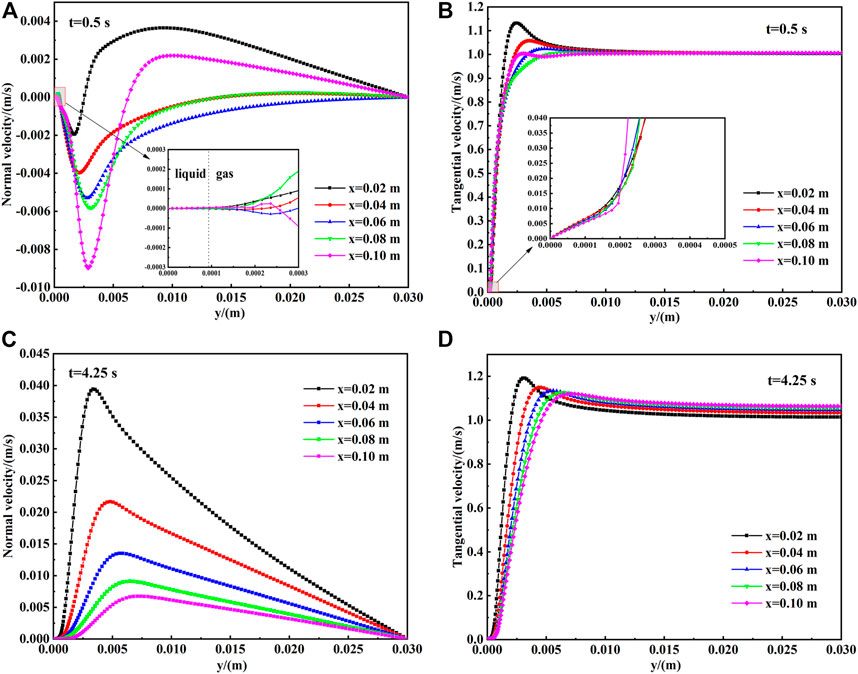
FIGURE 9. Velocity distributions in different positions on the wall in Case 2: (A) normal velocity at 0.5 s; (B) tangential velocity at 0.5 s; (C) normal velocity at 4.25 s; (D) tangential velocity at 4.25 s.
Outside the wall, the tangential velocity of the liquid film presents a linear distribution with an obvious velocity gradient. A local acceleration can be observed in the non-condensable gas layer far from the wall, after which the velocity of the fluid returns to the mainstream velocity. Along with the increase in distance in the x direction, the peak value of tangential velocity decreases gradually. The peak value of the tangential velocity at x = 0.1 m shifts to the left due to reflux in the outlet, and the return flow of the exit disappears at 4.5 s, as shown in Figure 9D. At this time, the pressure at the outlet is less than that at the inlet, and thus the velocity of the mainstream fluid increases gradually along the flow direction.
The velocity and temperature fields of the mixture on sections of the vertical plate at different times are shown in Figure 10. The value of the synergy angle between the velocity gradient and temperature gradient is close to 120° at the initial stage of condensation. According to the field synergy principle (Tao et al., 2002), the degree of synergy between the velocity field and the temperature field is good at this time, so the average heat transfer rate is high. When condensation proceeds for 4.25 s, the value of the synergy angle decreases to 98°, which is not beneficial to heat transfer, and the average heat transfer rate decreases slightly.
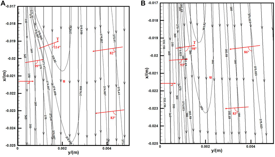
FIGURE 10. Temperature filed and velocity filed near the wall in Case 1: (A) t = 0.5 s; (B) t = 4.25 s.
During the condensation process of the steam-air mixture, the condensate adheres to the wall and forms a liquid film or bulge. Due to the interaction of surface tension, gravity, and sheer force at the phase interface, the liquid film cannot exist stably on the vertical wall and falls off, slides, and fluctuates along the wall. The isoline of liquid volume fraction with a value of 0.5 is used as the surface of the liquid film in this numerical simulation so as to obtain the form change of the liquid film, as shown in Figure 11. When the initial mass fraction of air is 0.3, the shape of the liquid film is very smooth at the beginning, the fluctuation is minimal, and the thickness is less than 0.05 mm. With continuous condensation, the liquid film gradually becomes thicker and begins to accumulate at the top of the liquid film, which produces a bulge. The bulge then slides along the wall and spreads downstream, so the liquid film gradually flows down along the wall. After that, with the condensate produced constantly, the liquid film reaches a pseudo-stable state with an alternate pattern of continuous formation and falls off, which can be defined as wavy liquid film.
Since the shapes of the condensate film change with time, the gas-liquid phase interface is similar to the dynamic rough surface, and the liquid film is surrounded by a layer of non-condensable gas. The condensate scours and merges with the liquids beneath during the liquid film fluctuation process. At the same time, this phenomenon also acts on the gas-liquid interface and the non-condensable gas layer, which changes the roughness of the dynamic surface and the partial concentration of the non-condensable gas layer near the phase interface. Figure 12 demonstrates that when the liquid film moves downstream with a slight deformation, the non-condensable gas layer undergoes local accumulation and reduction, which may influence the local thermal resistance. It should be noted that in the data processing, grids with a liquid fraction greater than 0.5 are deleted so that the white area without data represents the liquid film area. The mass transfer in the non-condensable gas layer near the phase interface is related to the shapes of the phase interface, which is consistent with Wang et al. (2016).
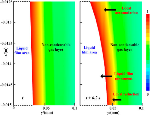
FIGURE 12. Local change of air concentration in the process of the liquid film falling off of Case 5.
Case 3 calculation results are used to obtain the total wall heat flux q, which is the sum of condensation and convection heat fluxes, in order to analyze the heat transfer further. The condensation heat flux qcond can be calculated from energy source terms in first-layer grids near the wall, which also determines the convection heat flux qconv. Through this method, the heat transfer due to condensation and convection can be clearly observed, as shown in Figure 13. The condensation and convection heat flux both decrease because of the increased thickness of the non-condensable gas layer, the thermal boundary layer, and the velocity boundary layer in the mixture flow direction. Meanwhile, the percentage of condensation heat transfer to total heat transfer gradually increases, reaching the maximum value of 0.975 at the bottom of the vertical plate.
The liquid film produced under working conditions of low non-condensable gas content is thick. If the liquid film is ignored, the calculation results will deviate significantly. To prove the importance of liquid film thermal resistance under these conditions, a thermal resistance analysis is carried out. In this model, the thermal resistance of the phase interface is neglected, and the liquid film and gas thermal resistances are calculated using Eqs. 15, 16.
Figure 14A shows the temperature distribution of the mixture near the wall at various positions. Because the thermal conductivities of gas and liquid are different, the points where the slopes of the temperature distribution curves change are taken as the gas-liquid interface, as marked by the circles in the figure. As shown in Figure 14B, the thermal resistances of the liquid film and the non-condensable gas layer increase gradually in the mixture flow direction as the non-condensable gas layer thickens. The thermal resistance of the liquid film accounts for 20%–26% of the total thermal resistance, illustrating that the effect of the liquid film should not be ignored in the condensation process.
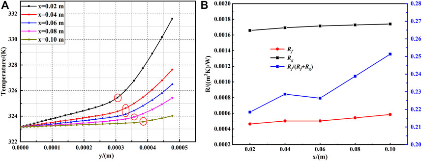
FIGURE 14. Heat transfer analysis in Case 3: (A) temperature distribution near the wall; (B) thermal resistance profile.
The combined WCM and VOF model is used to simulate the film condensation process of steam with non-condensable gas on a vertical plate. The purpose of the transient solver is to obtain the variations of the concentration and velocity fields in the non-condensable gas layer and the evolution of liquid film shapes for different non-condensable gas concentrations. The main conclusions are summarized as follows.
1) The high-concentration non-condensable gas layer is formed at the initial stage of condensation and then gradually diffused back to the mainstream as the condensation continues. The normal velocity of the steam-air gas mixture near the phase interface changes from the negative y-axis direction to the positive y-axis direction, which causes the degree of synergy between the temperature field and velocity field to decrease.
2) The shapes of the liquid film in different concentrations of non-condensable gases are observed, and the fluctuation, sliding, and falling off of liquid films can be presented in a single condensation process. In addition, heat and mass transfer at the phase interface can be affected by the obvious dynamic behavior of the liquid film, which changes the partial concentration distribution of the non-condensable gas boundary layer near the phase interface.
3) In this model, the thermal resistance of the liquid film is taken into account. For the working conditions of a gas mixture with a high content of steam, the proportion of condensation heat transfer is higher than 90%. The thermal resistance percentage of the liquid film can reach 20%–26% of the total thermal resistance. Therefore, the liquid film cannot be ignored to ensure the model’s accuracy.
The raw data supporting the conclusions of this article will be made available by the authors, without undue reservation.
SL: conceptualization, formal analysis. MW: supervision, writing–reviewing and editing. XW: validation, writing, original draft preparation, methodology.
The authors are extremely grateful to the Natural Science Foundation of Shandong Province for their financial support (No. ZR2019BEE012).
Author XW was employed by Tongyuan Design Group Co., Ltd.
The remaining authors declare that the research was conducted in the absence of any commercial or financial relationships that could be construed as a potential conflict of interest.
All claims expressed in this article are solely those of the authors and do not necessarily represent those of their affiliated organizations, or those of the publisher, the editors and the reviewers. Any product that may be evaluated in this article, or claim that may be made by its manufacturer, is not guaranteed or endorsed by the publisher.
Ahn, T., Moon, J., Kang, J., Jeong, J. J., and Yun, B. (2022). Steam condensation in the presence of non-condensable gas inside a nearly horizontal tube under separated flow. Int. J. Heat Mass Transf. 197, 123351. doi:10.1016/j.ijheatmasstransfer.2022.123351
Al-Diwany, H. K., and Rose, J. W. (1973). Free convection film condensation of steam in the presence of non-condensing gases. Int. J. Heat Mass Transf. 16, 1359–1369. doi:10.1016/0017-9310(73)90144-0
Alizadehdakhel, A., Rahimi, M., and Alsairafi, A. A. (2010). CFD modeling of flow and heat transfer in a thermosyphon. Int. Commun. Heat Mass Transf. 37, 312–318. doi:10.1016/j.icheatmasstransfer.2009.09.002
Anderson, M. H., Herranz, L. E., and Corradini, M. L. (1998). Experimental analysis of heat transfer within the AP600 containment under postulated accident conditions. Nucl. Eng. Des. 185, 153–172. doi:10.1016/s0029-5493(98)00232-5
Bejan, A. (1995). Convection heat transfer. New Jersey, United States: Wiley-Interscience Publication.
Brackbill, J. U., Kothe, D. B., and Zemach, C. (1992). A continuum method for modeling surface tension. J. Comput. Phys. 100, 335–354. doi:10.1016/0021-9991(92)90240-y
Choi, Y., Son, G., and Lee, G. (2020). Numerical simulation of wavy film condensation in a vertical channel with non-condensable gas. Int. J. Heat Mass Transf. 149, 119173. doi:10.1016/j.ijheatmasstransfer.2019.119173
Chung, B. J., Kim, S., and Kim, M. C. (2004). An experimental investigation of film condensation of flowing mixtures of steam and air on a vertical flat plate. Int. Commun. Heat Mass Transf. 31, 703–710. doi:10.1016/s0735-1933(04)00057-0
Colburn, A. P., and Hougen, O. A. (1934). Design of cooler condensers for mixtures of vapors with noncondensing gases. Industrial Eng. Chem. 26, 1178–1182. doi:10.1021/ie50299a011
Dehbi, A., Janasz, F., and Bell, B. (2013). Prediction of steam condensation in the presence of noncondensable gases using a CFD-based approach. Nucl. Eng. Des. 258, 199–210. doi:10.1016/j.nucengdes.2013.02.002
Denny, V. E., Mills, A. F., and Jusionis, V. J. (1971). Laminar film condensation from a steam-air mixture undergoing forced flow down a vertical surface. J. Heat Transf. 93, 297–304. doi:10.1115/1.3449814
Feurhuber, M., Magno, M., Miranda, M., and Hochenauer, C. (2019). CFD investigations of steam penetration, air-removal and condensation inside hollow loads and cavities. Appl. Therm. Eng. 147, 1070–1082. doi:10.1016/j.applthermaleng.2018.10.135
Fuller, E. N., Schettler, P. D., and Giddings, J. C. (1966). A new method for prediction of binary gas-phase diffusion coefficiients. Industrial Eng. Chem. 58, 19–27.
Hammoudi, D., Benabdesselam, A., Azzi, A., and Kassim, M. A. (2018). Numerical modeling of steam condensation in vertical channel in presence of noncondensable gas. Int. J. Therm. Sci. 126, 263–271. doi:10.1016/j.ijthermalsci.2017.12.032
Kharangate, C. R., Lee, H., Mascarehnas, N., Park, I., and Mudawar, I. (2016). Experimental and computational investigation of vertical upflow condensation in a circular tube. Int. J. Heat Mass Transf. 95, 249–263. doi:10.1016/j.ijheatmasstransfer.2015.11.010
Kharangate, C. R., and Mudawar, I. (2017). Review of computational studies on boiling and condensation. Int. J. Heat Mass Transf. 108, 1164–1196. doi:10.1016/j.ijheatmasstransfer.2016.12.065
Kleiner, T., Eder, A., Rehfeldt, S., and Klein, H. (2020). Detailed CFD simulations of pure substance condensation on horizontal annular low finned tubes including a parameter study of the fin slope. Int. J. Heat Mass Transf. 163, 120363. doi:10.1016/j.ijheatmasstransfer.2020.120363
Krishna, V. M., and Rao, V. D. (2017). Experimental study of condensation of humid air in laminar flow in a vertical channel. Heat Transf. Res. 48, 379–390. doi:10.1615/heattransres.2016007475
Kumar, G. V., Cammiade, L. M. F., Kelm, S., Prakash, K. A., Grob, E. M., Allelein, H. J., et al. (2021). Implementation of a CFD model for wall condensation in the presence of non-condensable gas mixtures. Appl. Therm. Eng. 187, 116546. doi:10.1016/j.applthermaleng.2021.116546
Lee, H., Kharangate, C. R., Mascarenhas, N., Park, I., and Mudawar, I. (2015). Experimental and computational investigation of vertical downflow condensation. Int. J. Heat Mass Transf. 85, 865–879. doi:10.1016/j.ijheatmasstransfer.2015.02.037
Lee, W. H. (1980). Pressure iteration scheme for two-phase flow modeling. Comput. methods two-phase flow Part. Transp. 1980, 61–82.
Lewis, W. K., and Whitman, W. G. (1924). Principles of gas absorption. Industrial Eng. Chem. 16, 1215–1220. doi:10.1021/ie50180a002
Li, J. (2013). CFD simulation of water vapour condensation in the presence of non-condensable gas in vertical cylindrical condensers. Int. J. Heat Mass Transf. 57, 708–721. doi:10.1016/j.ijheatmasstransfer.2012.10.051
Liao, Y., Vierow, K., Dehbi, A., and Guentay, S. (2009). Transition from natural to mixed convection for steam–gas flow condensing along a vertical plate. Int. J. Heat Mass Transf. 52, 366–375. doi:10.1016/j.ijheatmasstransfer.2008.06.008
Liu, Z., Sunden, B., and Yuan, J. (2012). VOF modeling and analysis of filmwise condensation between vertical parallel plates. Heat Transf. Res. 43, 47–68. doi:10.1615/heattransres.2012004376
Minkowycz, W. J., and Sparrow, E. M. (1966). Condensation heat transfer in the presence of noncondensables, interfacial resistance, superheating, variable properties, and diffusion. Int. J. Heat Mass Transf. 9, 1125–1144. doi:10.1016/0017-9310(66)90035-4
Peterson, P., Schrock, V., and Kageyama, T. (1993). Diffusion layer theory for turbulent vapor condensation with noncondensable gases. J. Heat Transf. 115, 998–1003. doi:10.1115/1.2911397
Punetha, M., and Khandekar, S. (2017). A CFD based modelling approach for predicting steam condensation in the presence of non-condensable gases. Nucl. Eng. Des. 324, 280–296. doi:10.1016/j.nucengdes.2017.09.007
Qiu, G., Cai, W., Li, S., Wu, Z., Jiang, Y., and Yao, Y. (2014). Numerical simulation on forced convective condensation of steam upward flow in a vertical pipe. Adv. Mech. Eng. 6, 589250. doi:10.1155/2014/589250
Rao, V. D., Krishna, V. M., Sharma, K. V., and Rao, P. V. J. M. (2008). Convective condensation of vapor in the presence of a non-condensable gas of high concentration in laminar flow in a vertical pipe. Int. J. Heat Mass Transf. 51, 6090–6101. doi:10.1016/j.ijheatmasstransfer.2008.03.027
Riva, E. D., and Col, D. D. (2012). Numerical simulation of laminar liquid film condensation in a horizontal circular minichannel. J. Heat Transf. 134, 1–8. doi:10.1115/1.4005710
Rose, J. W. (1980). Approximate equations for forced-convection condensation in the presence of a non-condensing gas on a flat plate and horizontal tube. Int. J. Heat Mass Transf. 23, 539–546. doi:10.1016/0017-9310(80)90095-2
Siow, E. C., Ormiston, S. J., and Soliman, H. M. (2007). Two-phase modelling of laminar film condensation from vapour-gas mixtures in declining parallel-plate channels. Int. J. Therm. Sci. 46, 458–466. doi:10.1016/j.ijthermalsci.2006.07.001
Sparrow, E. M., and Lin, S. (1964). Heat-transfer characteristics of polygonal and plate fins. Int. J. Heat Mass Transf. 7, 951–953. doi:10.1016/0017-9310(64)90150-4
Tang, G., Hu, H., Zhuang, Z., and Tao, W. (2012). Film condensation heat transfer on a horizontal tube in presence of a noncondensable gas. Appl. Therm. Eng. 36, 414–425. doi:10.1016/j.applthermaleng.2011.10.058
Tao, W., Guo, Z., and Wang, B. (2002). Field synergy principle for enhancing convective heat transfer-its extension and numerical verifications. Int. J. Heat Mass Transf. 45, 3849–3856. doi:10.1016/s0017-9310(02)00097-2
Wang, T., Tong, L., and Cao, X. (2022). Improvement of diffusion layer model for steam condensation in the presence of non-condensable gas under turbulent free convection. Appl. Therm. Eng. 213, 118631. doi:10.1016/j.applthermaleng.2022.118631
Wang, X., Chang, H., and Corradini, M. (2016). A CFD study of wave influence on film steam condensation in the presence of non-condensable gas. Nucl. Eng. Des. 305, 303–313. doi:10.1016/j.nucengdes.2016.06.003
Wang, Y., Zhao, Q., Zhou, Q., Kang, Z., and Tao, W. (2013). Experimental and numerical studies on actual flue gas condensation heat transfer in a left-right symmetric internally finned tube. Int. J. Heat Mass Transf. 64, 10–20. doi:10.1016/j.ijheatmasstransfer.2013.03.005
Yi, Q., Tian, M., Yan, W., Qu, X., and Chen, X. (2016). Visualization study of the influence of non-condensable gas on steam condensation heat transfer. Appl. Therm. Eng. 106, 13–21. doi:10.1016/j.applthermaleng.2016.05.134
Zhang, L., Zhang, G., Tian, M., Zhang, J., and Zhang, Y. (2019). Modeling of laminar filmwise condensation of methane with nitrogen on an isothermal vertical plate. Int. Commun. Heat Mass Transf. 105, 10–18. doi:10.1016/j.icheatmasstransfer.2019.03.018
Zhou, W., Henderson, G., and Revankar, S. T. (2010). Condensation in a vertical tube bundle passive condenser-Part 1: Through flow condensation. Int. J. Heat Mass Transf. 53, 1146–1155. doi:10.1016/j.ijheatmasstransfer.2009.10.039
Zschaeck, G., Frank, T., and Burns, A. D. (2014). CFD modelling and validation of wall condensation in the presence of non-condensable gases. Nucl. Eng. Des. 279, 137–146. doi:10.1016/j.nucengdes.2014.03.007
Aw area of the cell near the wall (m2)
Di mass diffusion coefficient for species i (m2/s)
DT,i thermal diffusion coefficient (m2/s)
E internal energy J)
hfg specific enthalpy (J/kg)
J molecular mass flux (kg/(m2·s))
keff effective thermal conductivity (W/(m·k))
mi mass flux of species i (kg/(m2·s))
p pressure (Pa)
q heat flux (W/m2)
qconv convection heat flux (W/m2)
qcond condensation heat flux (W/m2)
Rl thermal resistance of liquid film ((m2·K)/W)
Rg thermal resistance of gas ((m2·K)/W)
Re Reynolds number
Sh energy source term (W/m3)
Sm mass source term (kg/(m3·s))
T temperature (K)
Ti phase interface temperature (K)
Tw wall temperature (K)
u velocities (m/s)
Vc cell volume (m2)
wa mass fraction of air
ws mass fraction of steam
α volume fraction
δ thickness of liquid film (m)
κ interface curvature (1/m)
λl thermal conductivity of liquid film (W/(m·K))
ρ density (kg/m3)
σ surface tension coefficient (N/m)
τ stress-strain tensor
a air
c cell
g gas
l liquid
m mass
sat saturation
Keywords: film condensation, heat and mass transfer, non-condensable gas, gas-liquid two phase, computational fluid dynamics
Citation: Li S, Wei M and Wang X (2023) A numerical study on film condensation of steam with non-condensable gas on a vertical plate. Front. Energy Res. 11:1064067. doi: 10.3389/fenrg.2023.1064067
Received: 07 October 2022; Accepted: 18 January 2023;
Published: 09 February 2023.
Edited by:
Abdolali K. Sadaghiani, Sabancı University, TürkiyeReviewed by:
Yacine Addad, Khalifa University, United Arab EmiratesCopyright © 2023 Li, Wei and Wang. This is an open-access article distributed under the terms of the Creative Commons Attribution License (CC BY). The use, distribution or reproduction in other forums is permitted, provided the original author(s) and the copyright owner(s) are credited and that the original publication in this journal is cited, in accordance with accepted academic practice. No use, distribution or reproduction is permitted which does not comply with these terms.
*Correspondence: Min Wei, d2VpbWluQHNkdS5lZHUuY24=
Disclaimer: All claims expressed in this article are solely those of the authors and do not necessarily represent those of their affiliated organizations, or those of the publisher, the editors and the reviewers. Any product that may be evaluated in this article or claim that may be made by its manufacturer is not guaranteed or endorsed by the publisher.
Research integrity at Frontiers

Learn more about the work of our research integrity team to safeguard the quality of each article we publish.