 Liang Huang
 Chao Wu2
 Daniela Pagnani
- 1AAU Energy, Aalborg University, Aalborg, Denmark
- 2Department of Electrical Engineering, Shanghai Jiaotong University, Shanghai, China
- 3Electrical System Design and Grid Integration, Ørsted, Copenhagen, Denmark
As the capacity of wind power generation increases, grid-forming (GFM) wind turbine generators are deemed as promising solutions to support the system frequency for future low inertia power grids. So far, the GFM converter with a nearly ideal dc voltage source has been studied thoroughly. However, when the GFM converter is applied to wind power applications, there are some realistic problems and challenges, such as coordinating wind turbine control and GFM control, limited energy to support the grid, variable wind speed, etc. These problems still need more discussion. In this paper, an overview of challenges and potential solutions of GFM converters applied to wind power generation systems are provided, where different energy reserving schemes, GFM control schemes, and overcurrent protection schemes are compared and discussed. Finally, a few perspectives on future trends are shared according to the authors’ knowledge.
1 Introduction
In the past decades, due to the foreseen exhaustion of conventional fossil-based energies and their climate impact, many global efforts have been devoted to developing renewable energy sources (Blaabjerg et al., 2017). Among different energy sources, wind power grows rapidly due to its high energy density and easy obtainment (Brown, 2015). For example, wind power has already provided 50% of the total electricity consumption in Denmark (Hvelplund et al., 2017). Besides, the output characteristics of the wind generators (e.g., dynamic responses and steady-state error of output voltages and currents, terminal impedance/admittance characteristics, and power quality) highly depend on the control scheme of converters (Peyghami et al., 2019), (Van et al., 2021). Thus, the control scheme of wind generators will play an important role in the future power system (Rocabert et al., 2012; Olivares et al., 2014; Fraile, 2021).
Currently, the grid-following (GFL) control scheme with the phase-locked loop (PLL) has been widely used in the wind power generation system. However, as the penetration of wind energy increases, the system inertia and the grid strength will reduce dramatically. Thus, conventional GFL converters may suffer from frequency and voltage instability problems (UK National Grid, 2017). Although some improved GFL control methods, e.g., tuning PLL bandwidth (Wen et al., 2016), H-infinity tuning method (Egea-Alvarez et al., 2015), and impedance reshaping methods (Alawasa et al., 2014; Fang et al., 2018; Huang et al., 2022a), can enhance the voltage stability, the frequency stability issue is still hard to deal with. Besides, the island operation is a big challenge for GFL converters since they rely on the externally generated voltage. With the GFL control, the converters will shut down when there is a large disturbance or outage on the grid and wait for a signal that the disturbance has settled before restart.
To address the above issues, a new concept called “grid-forming” (GFM) converter has been proposed in recent years. Different from GFL converters, GFM converters can operate in the island case and provide frequency support to the grid, so they attract lots of research attention (Denis et al., 2017; Matevosyan et al., 2019; Wang et al., 2020a; Lasseter et al., 2020; Lin, 2020; Ndreko et al., 2020; Rosso et al., 2021; Li et al., 2022). So far, various GFM control schemes, such as droop control (Brabandere et al., 2007), (Guerrero et al., 2005), and virtual synchronous generator (VSG) control (Beck and Hesse, 2007; D'Arco and Suul, 2013; Bevrani et al., 2014; Liu et al., 2016), have been proposed in existing literature (Brabandere et al., 2007; Guerrero et al., 2005; Beck and Hesse, 2007; D'Arco and Suul, 2013; Bevrani et al., 2014; Liu et al., 2016; Zhong and Weiss, 2011; Zhang et al., 2010; Zhang et al., 2016; Groß et al., 2019). Besides, some improved control schemes, such as virtual impedance (He and Li, 2011; Rodriguez et al., 2013; Vasquez et al., 2013), tuning inertia and damping (Alipoor et al., 2015), are also developed to enhance the small-signal stability and transient stability of GFM converters (He and Li, 2011; Rodriguez et al., 2013; Vasquez et al., 2013; Alipoor et al., 2015; Wang et al., 2020b; Du et al., 2020; Liao et al., 2020; Wu and Wang, 2020; Huang et al., 2021a; Arasteh et al., 2022; Huang et al., 2022c). Moreover, the single-loop and multiple-loop GFM controls are two widely used schemes (Du et al., 2020). The single-loop scheme is relatively simple, but it relies on the passive L-C filters to filter out the harmonics. When the L-C filter is small, its filter performance is limited. Differently, the multiple-loop scheme has an equivalent active resistance introduced by the inner current control loop, which is beneficial to reduce the harmonics and improve the power quality of the GFM inverters.
When the GFM control technology is applied to wind power generation systems, the energy reserving scheme, the dc-link voltage control scheme, and the cooperative control of the machine-side and grid-side should be taken into account. For the type-3 wind generators, the dc-link voltage is usually controlled by the grid-side converter (GSC), so that the GFM control can be performed on the rotor-side converter (RSC). Differently, for the type-4 wind generators, the dc-link voltage can be controlled by either the GSC or the machine-side converter (MSC) (Huang et al., 2021b). Moreover, if there is an additional battery energy storage system (BESS) on the dc-link, the dc-link voltage is able to be controlled by the BESS (Fang et al., 2019). Thus, different dc-link voltage control methods are worth being compared (Nguyen et al., 2022). Besides, to provide frequency support to the grid, the wind generator should reserve some additional energy, so that the deloading operation of the generator may be necessary (Kumar et al., 2020). In this paper, several energy reserving schemes, dc-link voltage control schemes, and overcurrent protection schemes for wind generators are reviewed, where type-3 and type-4 wind generators are the study focus.
Overall, the main contribution of this paper can be summarized as follows:
1) A comprehensive review and comparison among different GFM control schemes for type-3 and type-4 wind generators are presented in this paper, which provides a good reference for scholars and engineers in the wind power generation field.
2) In this paper, the authors not only review different energy reserving schemes, GFM control schemes, and overcurrent protection schemes, but also share personal perspectives about the potential solutions according to the authors’ research experience.
3) The main challenges of applying GFM control technology to wind turbine applications are summarized, and several possible future research directions are proposed in this paper.
The rest of this paper is organized as follows: Firstly, in order to meet the basic requirement of having backup energy, three energy reserving schemes for wind generators are discussed in Section 2. Then, from the control perspective, several possible GFM control schemes of wind generators are compared in Section 3, where type-3 and type-4 wind generators are included. In Section 4, different overcurrent protection strategies used for abnormal grid conditions are discussed. In Section 5, a few perspectives on current challenges and future trends are summarized. Finally, this paper is concluded in Section 6.
2 Energy reserving schemes of wind generators
First of all, having backup energy is a basic requirement for GFM-based wind generators. So, several energy reserving schemes are discussed in this section. For the typical wind generation system without BESS, some wind energy (e.g., 10%–20%) should be reserved, so that this backup energy can be used to support the grid frequency when the load increases. In this case, the generator does not follow the maximum power point tracking (MPPT) curve anymore. Instead, the generator follows a new deloading curve that is lower than the MPPT curve, as shown in Figure 1.
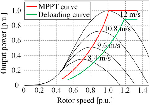
FIGURE 1. Wind turbine characteristics for normal and deloading operating modes (Ducar et al., 2017).
Moreover, if there is an additional BESS to store the energy, the deloading operation is not necessary. The generator can follow the MPPT curve to generate the maximum power, because the wind energy can be stored in the BESS. Under this circumstance, the backup energy in the BESS can be used to support the grid frequency when the load increases.
Based on the above analysis, three possible energy reserving schemes are shown in Figure 2, which are suitable for either type-3 or type-4 wind generators. As shown in Figure 2A, if there is no additional BESS in the wind generator, the wind turbine (WT) needs to operate in the deloading mode to reserve some wind energy (Vidyanandan and Senroy, 2013; Ducar et al., 2017; Krpan and Kuzle, 2020; Kumar et al., 2020; Dong et al., 2021). This is a possible way for the wind generator to achieve the GFM function, but it is not the best way from an economic point of view, because some potential wind energy is wasted. Alternatively, if an additional BESS is added to the wind generator, the deloading operation is not necessary. Namely, the wind generator can still operate in MPPT mode. The BESS can be added on either the dc-side or the ac-side. As shown in Figure 2B, when the BESS is added on the dc-side, the GSC can be controlled as a GFM converter (Chen et al., 2021). Meanwhile, the MPPT control can be performed on the machine-side. However, the energy support ability of this scheme may be limited by the capacity of the battery. Besides, the lifetime of the battery and the maintenance cost also need to be considered, especially for the offshore wind farm. Moreover, as shown in Figure 2C, when the BESS is added on the ac-side, the BESS can be controlled as a GFM converter (Kouassi and Francois, 2016; Chen et al., 2021; Zhao et al., 2022). Relatively, there are fewer physical restrictions for this scheme because the BESS can be placed far from the wind generators. Besides, the existing wind generators with GFL control can still be used without any modification. Therefore, this scheme is easier to be implemented compared with the previous two schemes. However, the island operation or black start of the GFL-based wind generator is a challenge. A possible way is to make use of the BESS for black start (Pagnani et al., 2022). Namely, during the black-out, the BESS with GFM control in Figure 2C is used to establish the local grid voltage. After the local grid voltage is established, the GFL-based wind generators can restart for normal operation. However, this solution requires a large capacity of the BESS. In addition, another possible way is a combination of the schemes in Figures 2A, C. For example, the scheme in Figure 2C can be used for the normal grid-connected condition, while the scheme in Figure 2A can be used for the islanded condition.
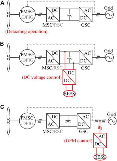
FIGURE 2. Three possible energy reserving schemes for wind generation systems. (A) Deloading operation of the wind turbine (Vidyanandan and Senroy, 2013; Ducar et al., 2017; Krpan and Kuzle, 2020; Kumar et al., 2020; Dong et al., 2021); (B) Adding an energy storage system on the dc-side (Chen et al., 2021); (C) Adding an energy storage system on the ac-side (Kouassi and Francois, 2016; Chen et al., 2021; Zhao et al., 2022).
3 Grid-forming control schemes of wind generators
When the basic requirement of having the energy backup is satisfied, the specific GFM control scheme will be the key point to achieve GFM function on wind generators. Nowadays, type-3 and type-4 wind generators have been widely used in the wind generation field (Kushwaha and Singh, 2013). The type-4 wind generator is usually equipped with a permanent-magnet synchronous generator (PMSG) and a full-scale power converter. Although other types of generators, such as squirrel-cage induction generator (SCIG) and would-rotor synchronous generator (WRSG), can also be used for the type-4 wind generation system, the PMSG-based wind generator is more popular (Nguyen et al., 2022). So, the PMSG-based type-4 wind generator is chosen as an example for analysis in this paper. Moreover, the type-3 wind generator is equipped with a doubly-fed induction generator (DFIG) and a partial-scale power converter. Since a partial-scale (e.g., 33%) power converter is much cheaper than a full-scale power converter, the cost of the type-3 wind generator is usually lower than that of the type-4. However, the gearbox is necessary for the type-3 wind generator, which may increase the maintenance cost. Differently, the type-4 wind generator with a direct-driver PMSG can eliminate the gearbox. Besides, since the PMSG does not need additional exciting current, the efficiency of the PMSG is generally higher than that of the DFIG. Therefore, either type-3 or type-4 wind generators have their own advantages and limitations. This section will review and compare different GFM control schemes for type-3 and type-4 wind generators.
3.1 Generalized GFM control structure
Although there are many alternative control schemes to achieve the GFM function, they follow the same power-synchronization control (PSC) law as the traditional synchronous generator (SG). Thus, a generalized GFM control structure is summarized in (Rosso et al., 2021) to highlight its main features. As shown in Figure 3, the generalized GFM control structure consists of inner voltage/current control loops and outer power control loops, where the active power is related to the phase angle and the reactive power is related to the voltage magnitude. Besides, a voltage reference E∠θ is generated by the active power and reactive power controller at the outer loop, which can be achieved by the droop control, VSG control, proportional-integral (PI)-based synchronous power control, virtual oscillator control, etc. Notably, the droop or VSG control has a steady-state error, while the PI-base control is able to eliminate the steady-state error. In addition, it is worth mentioning that this control scheme may not be suitable for low-voltage applications with a higher ratio of resistance and inductance. However, this paper mainly focuses on high-voltage applications rather than low-voltage applications.
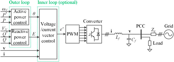
FIGURE 3. Generalized control structure of a GFM converter (Rosso et al., 2021).
Moreover, the inner voltage and current controllers in Figure 3 are optional. When the inner control loop is eliminated, the modulation voltage e’ is the same as E∠θ. However, when the inner control loop is included, the output voltage v tracks the voltage reference E∠θ. Thus, the modulation voltage e’ can be generated automatically based on the closed-loop control. Generally, including the inner control loops may increase the control complexity, but it provides additional benefits, such as accurate current control, flexible virtual impedance implementation, and improved filter performance. Besides, including the inner control loops is also beneficial for applying the current limitation to protect the converter against grid faults, which will be discussed in Section 4.
In order to demonstrate the advantages of the GFM converter over the GFL converter, simulation results of a grid-connected converter with the typical GFL control and GFM control are shown in Figure 4. Initially, when the converter is connected to the grid, both the GFL and GFM converters work well. However, when the grid is disconnected at the instant of 5 s, the GFL converter becomes unstable, while the GFM converter is still stable. Therefore, the GFM control is very important for the stable operation of converter-interfaced generators.
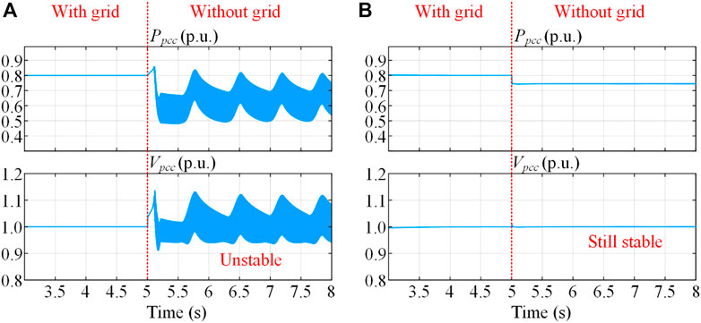
FIGURE 4. Simulation results of a grid-connected converter with different control schemes. (A) With grid-following control; (B) With grid-forming control.
3.2 GFM control schemes of type-4 wind generators
For the back-to-back converter in type-4 wind generators, the dc-link voltage can be controlled by either the GSC or the MSC. Besides, if there is an additional BESS on the dc-link, the dc-link voltage is able to be controlled by the BESS. Therefore, three categories of dc-link voltage control schemes are shown in Figures 5–7, respectively.
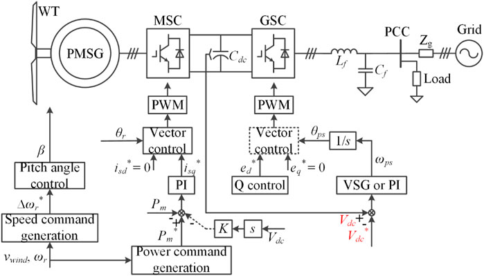
FIGURE 5. GFM control scheme of type-4 wind generator with grid-side dc voltage control (Li et al., 2017; Xi et al., 2017; He et al., 2018; Sang et al., 2019; Li et al., 2021).
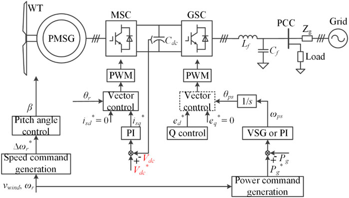
FIGURE 6. GFM control scheme of type-4 wind generator with machine-side dc voltage control (Duckwitz et al., 2014; Zhong et al., 2015; Kim et al., 2018; Günther and Sourkounis, 2019; Shan et al., 2019; Yazdi et al., 2019; Yan et al., 2020; Xi et al., 2021; Avazov et al., 2022).
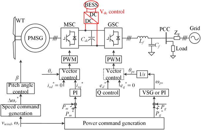
FIGURE 7. GFM control scheme of type-4 wind generator with battery energy storage system connected to the dc-link (Ma et al., 2016; Ma et al., 2017; Fang et al., 2019).
The grid-side dc-link voltage control scheme has been introduced in (Li et al., 2017; Xi et al., 2017; He et al., 2018; Sang et al., 2019; Li et al., 2021), which is shown in Figure 5. The control scheme of the MSC is basically the same as the conventional power control method. However, the control scheme of the GSC is different from the conventional dc-link voltage control scheme based on the PLL. Specifically, the dc-link voltage can be controlled by adjusting the output power by changing the phase angle of the output voltage reference. Besides, the magnitude of the output voltage reference is generated by a reactive power controller. Thus, alternative ways, such as droop control, VSG control, and PI control, can be used to control the dc-link voltage. Notably, when the VSG control is used, a steady-state error exists, so that the dc-link voltage cannot be controlled as same as the reference value. Differently, when the PI control is used, there is no steady-state error, so the dc-link voltage can be controlled as same as the reference value. Moreover, the inner loop of the voltage and current vector control is optional. In (Xi et al., 2017; He et al., 2018; Sang et al., 2019; Li et al., 2021), the inner loop is not included, while the inner loop is included in (Li et al., 2017). In addition, for the machine-side control scheme, a feedforward term from the dc-link voltage to the power reference can be added. Thus, the MSC can provide some transient energy to support the dc-link voltage (Sang et al., 2019).
The main advantage of the grid-side dc-link voltage control scheme is that the typical machine-side control scheme can be inherited, which is a proven and mature method (Nguyen et al., 2022). However, the island operation is a challenge for this method because the dc-link voltage control relies on the grid voltage.
The machine-side dc-link voltage control scheme has been introduced in (Duckwitz et al., 2014; Zhong et al., 2015; Kim et al., 2018; Günther and Sourkounis, 2019; Shan et al., 2019; Yazdi et al., 2019; Yan et al., 2020; Xi et al., 2021; Avazov et al., 2022), which is shown in Figure 6. The dc-link voltage is controlled by adjusting the machine-side input power by regulating the torque. Thus, the general GFM control scheme can be used for the GSC to achieve the GFM function, where the VSG or PI control is chosen as an example in Figure 6. Since the power is not controlled by the MSC, the power reference is sent to the GSC rather than the MSC for power control. Besides, the inner loop of the voltage and current vector control is optional. In (Duckwitz et al., 2014; Zhong et al., 2015; Kim et al., 2018; Günther and Sourkounis, 2019; Shan et al., 2019; Xi et al., 2021; Avazov et al., 2022), the inner loop is not included, while the inner loop is included in (Yazdi et al., 2019)- (Yan et al., 2020).
The main advantage of the machine-side dc-link voltage control scheme is that the dc-link voltage is provided by the MSC, which does not rely on the grid voltage anymore. Thus, the island operation or black start of the wind generator can be easily achieved (Shan et al., 2019), (Kim et al., 2018). Besides, the overall behavior of the PMSG plus the MSC is like a dc voltage source rather than a dc current source (Huang et al., 2021b), which is beneficial for the GSC to provide energy support to the grid.
Moreover, as shown in Figure 7, if an additional BESS is connected to the dc-link of the back-to-back converter, the dc-link voltage can be controlled by the BESS (Ma et al., 2016; Ma et al., 2017; Fang et al., 2019). Obviously, this scheme needs additional hardware extension, but it provides another degree of freedom for control. Namely, the power control can be achieved on both the MSC and the GSC, which is beneficial for optimizing the power flow through the back-to-back converter and stabilizing the dc-link voltage. Besides, the conventional power control method on the MSC can be inherited, which is a mature method. Moreover, alternative GFM control schemes can be used for the GSC, where the VSG or PI control is chosen as an example shown in Figure 7.
From the technical point of view, the GFM control scheme with the BESS is better than the previous two methods in Figures 5, 6, because the typical machine-side control scheme can be inherited without any modification and the island operation can be easily achieved by using the BESS. However, there are some obvious drawbacks for this scheme. Firstly, adding the BESS increases the cost of the wind generation system. Secondly, the installation of the battery needs more physical space, which may be a problem if the space is limited in the nacelle of wind generators. Thirdly, the lifetime of the battery is usually not so long as that of the power electronic devices, which may increase the additional maintenance cost. Therefore, from the practical application perspective, the GFM control scheme shown in Figure 7 may not be a highly competitive scheme for type-4 wind generators.
In order to compare advantages and disadvantages of GFM type-4 wind generators with grid-side dc voltage control and machine-side dc voltage control, simulation results of GFM type-4 wind generators are presented in Figure 8. As shown in Figure 8A, with the grid-side dc voltage control, the dc-link voltage cannot be controlled to be a constant when the grid is disconnected, because the input power (depending on the wind speed) and the output power (determined by the load in island cases) are not equal anymore. Thus, the dc-link voltage will continue to increase or decrease. Finally, the wind generation system will become unstable. Differently, as shown in Figure 8B, with the machine-side dc voltage control, the dc-link voltage can be controlled to be the rated value no matter whether the grid is connected or not. This is because the input power is always adjusted according to the dc-link voltage, which can keep the input power equal to the output power in the steady state.
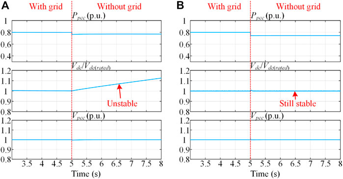
FIGURE 8. Simulation results of GFM type-4 wind generators with different dc-link voltage control schemes. (A) With grid-side dc voltage control; (B) With machine-side dc voltage control.
Overall, the advantages and disadvantages of the aforementioned three dc-link voltage control schemes of type-4 wind generators are compared in Table 1. It can be seen from Table 1 that each method has its own advantages and limitations. Thus, further studies are necessary to address these limitations. From the authors’ viewpoint, the machine-side dc-link voltage control scheme may have more potential, because the control of the wind generator does not rely on the grid.
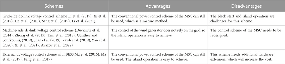
TABLE 1. Comparison of three dc-link voltage control schemes of type-4 wind generators.
3.3 GFM control schemes of type-3 wind generators
For the type-3 wind generators, the GFM function is usually achieved on the machine-side, while the dc-link voltage is often controlled by the GSC. In general, two types of control methods can be used for the GSC, which are the typical GFL control with a PLL and the PSC. However, no matter which method is used, the grid voltage is essential to establish the dc-link voltage, so the black start is a challenge for the type-3 wind generators. To achieve the black-start function, an additional auxiliary dc voltage source may be necessary. In this section, three possible dc-link voltage control schemes for type-3 wind generators are reviewed and discussed.
The GFM control scheme of type-3 wind generator with the PLL-based dc voltage control has been introduced in (Huang et al., 2017; Jiao and Nian, 2020; Shah and Gevorgian, 2020; Oraa et al., 2022), which is shown in Figure 9. The general GFM control scheme in Figure 3 can be used for the RSC to achieve the GFM function, while the conventional GFL control method with a PLL is used for the GSC to control the dc-link voltage. The main advantage of this scheme is that the typical GFL control method on the GSC is a mature method (Oraa et al., 2022), (Shah and Gevorgian, 2020).
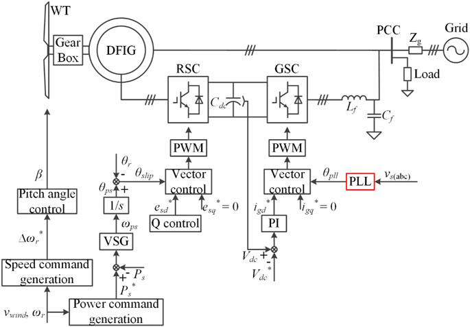
FIGURE 9. GFM control scheme of type-3 wind generator with PLL-based dc voltage control (Huang et al., 2017; Jiao and Nian, 2020; Shah and Gevorgian, 2020; Oraa et al., 2022).
Moreover, the GFM control scheme of type-3 wind generator with the PSC-based dc voltage control has been introduced in (Shao et al., 2019), which is shown in Figure 10. The general GFM control scheme in Figure 3 can be used for the RSC, while the power synchronization (or called “inertial synchronization”) control is used for the GSC to control the dc-link voltage. Thus, both the RSC and the GSC have the GFM functions. In order to compare advantages and disadvantages of GFM type-3 wind generators with PLL-based dc voltage control and PSC-based dc voltage control, simulation results of GFM type-3 wind generators are presented in Figure 11.
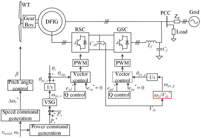
FIGURE 10. GFM control scheme of type-3 wind generator with PSC-based dc voltage control (Shao et al., 2019).
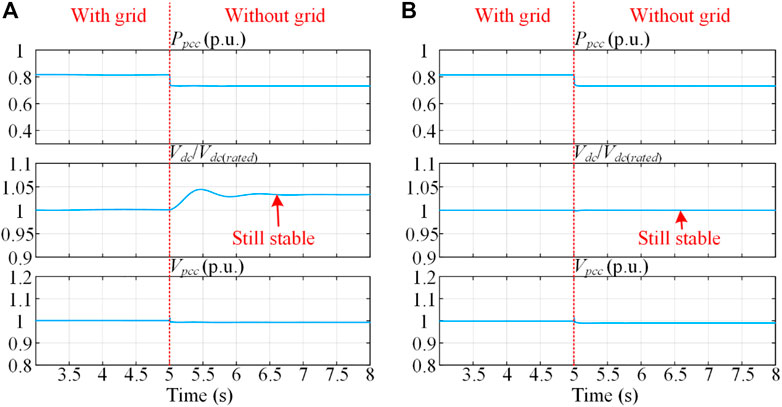
FIGURE 11. Simulation results of GFM type-3 wind generators with different dc-link voltage control schemes. (A) With PSC-based dc voltage control; (B) With PLL-based dc voltage control.
As shown in Figure 11, GFM type-3 wind generators with PSC-based or PLL-based dc-link voltage control schemes can operate stably after the grid is disconnected, but the dynamic and steady-state characteristics of these two methods are different. It can be seen from Figure 11A that the dc voltage dynamic response by using PSC-based dc voltage control is relatively slow, and the steady-state dc voltage is not equal to the rated value. Differently, it can be seen from Figure 11B that the dc voltage dynamic response by using PLL-based dc voltage control is relatively fast, and the steady-state dc voltage can be controlled as same as the rated value. Therefore, from the authors’ viewpoint, the PLL-based dc voltage control scheme may have more potential.
Although type-3 wind generators with the above two GFM control schemes can operate in the island case, the black start is still a big challenge. To achieve the black start, another scheme with an auxiliary uninterrupted power supply (UPS) on the dc-link has been proposed in (Zhu et al., 2018) and (Rodríguez-Amenedo et al., 2021), as shown in Figure 12. The overall control scheme of this method is basically the same as the control scheme in Figure 9. However, since an auxiliary UPS is added to the dc-link, the wind generator has the black start capability. Namely, the UPS is connected to the dc-link during the start-up process to energize the dc bus. Thus, the RSC operates initially to establish the stator-side voltage. Then, the GSC can be used to control the dc-link voltage. After the start-up process is finished, the UPS is disconnected. Obviously, having the black start capability is a major advantage of this scheme. However, since the additional auxiliary UPS is added, the cost of this scheme is higher than the previous two schemes without the UPS. Besides, additional maintenance cost for the UPS is also inevitable.
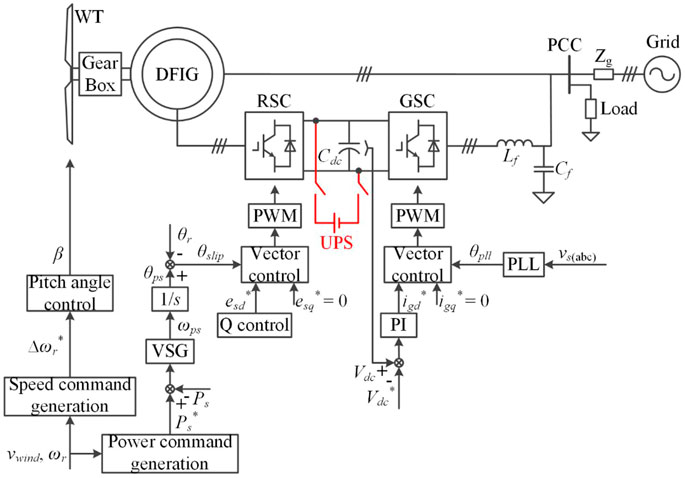
FIGURE 12. GFM control scheme of type-3 wind generator with an auxiliary UPS on the dc-link (Zhu et al., 2018), (Rodríguez-Amenedo et al., 2021).
Overall, the advantages and disadvantages of the above three GFM control methods of type-3 wind generators are compared in Table 2. The RSC controls of these three methods are basically the same. However, the main difference is whether to have a PLL or an auxiliary UPS. Relatively, the PLL-based control scheme is a mature method. However, the PSC-based control scheme is a newly developed method, which has not been widely used. So, this scheme still needs more exploration. Besides, the black start is a big challenge for the type-3 wind generator. Adding an auxiliary UPS or battery on the dc-link may be necessary to achieve the black start function.
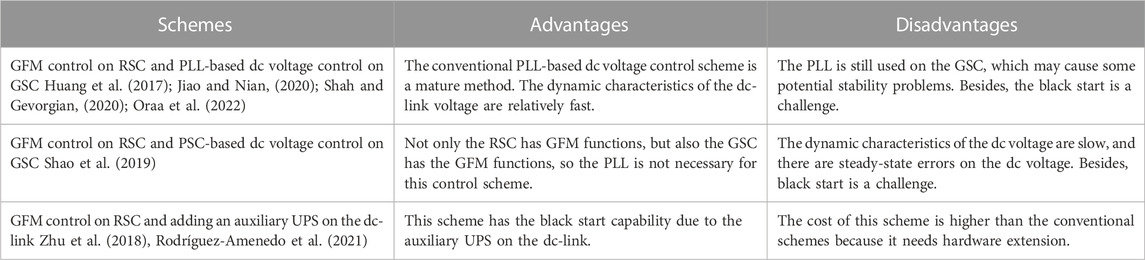
TABLE 2. Comparison of three dc-link voltage control schemes of type-3 wind generators.
4 Overcurrent protection schemes of GFM converters under abnormal grid conditions
Although the aforementioned GFM control schemes can work under normal grid conditions, they still have some problems under abnormal grid conditions. Specifically, since power-electronics-based converters are only able to bear a few percent of overcurrent (typically 20%), the converters have the risk of overcurrent under grid fault or overload conditions, which may damage the power converters. In order to protect the GFM converters against extreme grid faults, such as short circuits, heavy load connection, and line-tripping/reclosing, additional overcurrent protection is necessary (Xin et al., 2016; Awal and Husain, 2021; Rokrok et al., 2022). In this section, several overcurrent protection schemes are discussed.
As shown in Figure 13, six overcurrent protection strategies are reviewed, which are the control-mode-switching method (Oureilidis and Demoulias, 2016), virtual impedance method (Paquette and Divan, 2015), modifying power reference method (Taul et al., 2020), voltage-based frequency feedforward method (Huang et al., 2019), power-based frequency feedforward method (Du et al., 2019), and virtual power angle limiting method (Huang et al., 2022b). The key performances of these overcurrent protection methods are compared in Table 3.
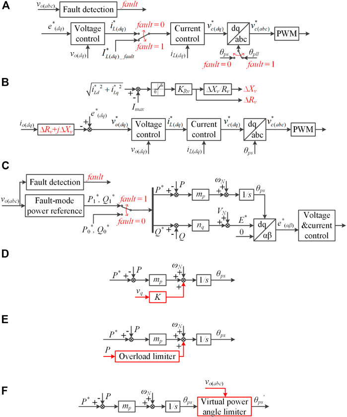
FIGURE 13. Overcurrent protection schemes of GFM converters. (A) Control-mode-switching method (Oureilidis and Demoulias, 2016), (B) Virtual impedance method (Paquette and Divan, 2015), (C) Modifying power reference method (Taul et al., 2020), (D) Voltage-based frequency feedforward method (Huang et al., 2019), (E) Power-based frequency feedforward method (Du et al., 2019), (F) Virtual power angle limiting method (Huang et al., 2022b).
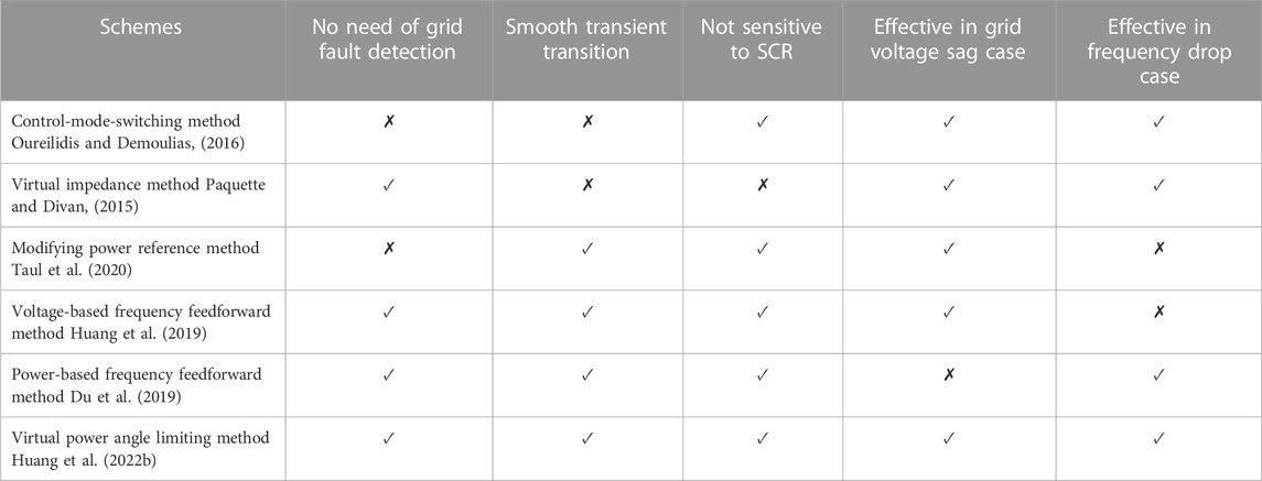
TABLE 3. Comparison of different overcurrent protection schemes of GFM converters (Huang et al., 2022b).
The control-mode-switching method is shown in Figure 13A. The idea of this method is to switch the control mode from the GFM mode to the GFL mode when the grid fault happens. When the fault is cleared, the control mode is switched back to the GFM mode. By using this method, the current can be limited to a designed fixed value during the fault. However, grid fault detection is necessary for this method, which increases the complexity. Besides, during the recovery process, the wind-up issue of the integrator may worsen the transient performance.
The virtual impedance method is shown in Figure 13B. The idea of this method is adding a large virtual impedance between the converter and the grid, so that the output current can be limited. By using this method, grid fault detection is not necessary. However, the performance of this method is sensitive to the grid impedance (Taul et al., 2020). Besides, the steady-state current cannot be limited to a designed fixed value during the fault, which varies under different grid conditions.
The modifying power reference method is shown in Figure 13C. The idea of this method is to reduce the power reference when a grid fault happens. This method is effective in the grid voltage sag case. However, it is not effective in the grid frequency drop case. Besides, grid fault detection is necessary for this method.
The voltage-based frequency feedforward method is shown in Figure 13D. This method makes use of the q-component voltage to add a frequency feedforward term to the P-f droop controller, which is effective in the grid voltage sag case. Besides, it is not necessary to switch the control structure by using this method. However, it is not effective in the grid frequency drop case.
The power-based frequency feedforward method is shown in Figure 13E. Based on the value of the active power, a frequency feedforward term is added to the P-f droop controller. This method is effective in the grid frequency drop case, but it is not effective in the grid voltage sag case.
The virtual power angle limiting method is shown in Figure 13F. A stable equilibrium point always exists in either grid voltage sag cases or grid frequency drop cases, so the stability of GFM converters under large grid disturbances can be guaranteed by using this method. Besides, it is not necessary to switch the control structure or parameter, and the additional grid fault detection is also not necessary. Therefore, from the authors’ point of view, this method is a promising solution to protect GFM converters against overcurrent.
5 Future trends
Although some possible solutions for reserving the wind energy, controlling the dc-link voltage, and implementing overcurrent protection have been proposed so far, there are still some challenges and open issues regarding applying GFM control technology in the wind generators, which will be discussed briefly in this section.
5.1 Determining capacity of dc-link capacitor in type-4 wind generators
For the type-4 wind generators, the PMSG is connected to the grid through a back-to-back converter. Since the dynamic response of the PMSG is generally slower than that of the converter, the dc-link capacitor plays the role of the energy buffer to provide short-term energy to the grid. Thus, the dc-link voltage is hard to be maintained constantly if the dc-link capacitor is not large enough. Therefore, to achieve the GFM function, the capacity of the dc-link capacitor needs to be increased (Lund et al., 2020). However, further evaluation is required to determine the appropriate size of the capacitor.
5.2 Reducing the mechanical stress on the turbine in type-3 and type-4 wind generators
It is reported in (Shah and Gevorgian, 2020) that the mechanical stress of type-3 wind generators with GFM control is higher than that of the conventional GFL control, due to a slower speed of the active power control. Similar phenomena are observed in type-4 wind generators with the machine-side dc-link voltage control. In (Avazov et al., 2022), the cause of this mechanical stress on the wind generator for type-4 is investigated and it is found that they appear in the form of torsional vibrations and their trigger may be a rapid variation of the electromagnetic torque, which in turn can be caused by grid frequency variations. The addition of damping in the system (internal and/or external) is one of the applied solutions for future work (Roscoe et al., 2019). Considering that higher mechanical stress may reduce the lifetime of the turbine, an improved control method to reduce the mechanical stress on the turbine is worth studying further.
5.3 Coordinating wind turbine control and GFM control
For the conventional GFL-based wind generators, the operation of the WT mainly depends on the wind speed (i.e., following the MPPT curve), which is relatively simple. Differently, for the GFM-based wind generators, both the wind speed and the power demand of the grid should be considered to modify the operating point of the WT (Ma et al., 2016), which becomes more complicated. Therefore, coordinating the WT control and the GFM control still needs more studies.
5.3 Seamless transition between GFL control mode and GFM control mode
Considering that a sufficient energy supply is essential for GFM converters, it is more reasonable for wind generators to operate in the GFM mode when the wind speed is high, while they run in the conventional GFL mode when the wind speed is low. Thus, the seamless transition between the GFL control mode and the GFM control mode is necessary (Tayyebi et al., 2020). Therefore, an effective method to switch between the GFL and GFM modes smoothly is worth being developed in the future.
5.4 Analyzing the impact of dc current limitation on GFM-based wind generators
So far, the impact of the ac current limitation on the GFM inverter has been studied a lot. In fact, the dc current limitation is also important for the back-to-back converter to make sure the converter operates within the rated current range (Tayyebi et al., 2020). It is questionable whether the GFM function can still be achieved when the dc current is limited, which needs further exploration.
5.5 Analyzing transient stability of GFM-based wind generators
Currently, although the small-signal stability of GFM-based converters/wind generators has been widely analyzed, the transient characteristics still need more studies, which belongs to a large-signal problem, including grid voltage dip, phase jump, etc (Pan et al., 2020; Chen et al., 2022; Huang et al., 2022c; Liu et al., 2022; Luo et al., 2023). However, it is very difficult to analyze the stability of a high-order (i.e., higher than second-order) nonlinear system. Hence, analyzing the transient stability of GFM-based converters/wind generators by using a reduced-order model is a possible way, which needs further investigation.
5.6 Optimizing the proportion of GFL-based and GFM-based wind generators
As known, conventional GFL-based wind generators can output the maximum power by following the MPPT curve. However, it is not possible to use 100% GFL-based generators in a power system. Differently, it is possible to use 100% GFM-based generators in a power system, but the output power of the GFM-based generators is not as high as that of the GFL-based generators because some energy should be reserved to support the grid. Hence, the power system with mixed GFL-based generators and GFM-based generators may have complementary benefits. Thus, optimizing the proportion of the GFL-based and the GFM-based wind generators is an interesting research topic.
6 Conclusion
This paper provides an overview of possible solutions for applying the GFM control technology in the type-3 and type-4 wind generators. The main difference between a GFM-based wind generator and a GFM inverter is whether having a strong dc-link voltage source on the dc-side. Due to the fact that there is no dc voltage source in the wind generator, the dc-link voltage needs additional control, and the generated energy from the WT needs to be reserved. Therefore, several dc-link voltage control schemes and energy reserving schemes are discussed. Compared with the grid-side dc-link voltage control scheme, the machine-side dc-link voltage control scheme for type-4 wind generators may have more potential because it does not rely on the grid voltage. Compared with the PSC-based dc voltage control scheme, the PLL-based dc voltage control scheme for type-3 wind generators may have more potential because it has fast dynamic characteristics and zero steady-state error on the dc-link voltage. Besides, the deloading operation is an effective way to reserve wind energy for both type-3 and type-4 wind generators, but part of wind energy is wasted during deloading operation. Although adding an additional BESS may have more benefits, it may cause other problems, such as a higher cost, reliability issues of the battery, etc. Furthermore, when considering abnormal grid conditions with large voltage and frequency disturbances, an effective overcurrent protection scheme is necessary for GFM converters. A recently proposed virtual power angle limiting method does not have obvious drawbacks compared with other methods, which seems to be a promising solution. Finally, perspectives on future trends are shared according to the authors’ knowledge.
Author contributions
Writing—original draft preparation, LH; writing—review and editing, CW, DZ, LC, DP, and FB. All authors have read and agreed to the published version of the manuscript.
Conflict of interest
DP was employed by the company Ørsted.
The remaining authors declare that the research was conducted in the absence of any commercial or financial relationships that could be construed as a potential conflict of interest.
Publisher’s note
All claims expressed in this article are solely those of the authors and do not necessarily represent those of their affiliated organizations, or those of the publisher, the editors and the reviewers. Any product that may be evaluated in this article, or claim that may be made by its manufacturer, is not guaranteed or endorsed by the publisher.
References
Alawasa, K. M., Mohamed, Y. A. I., and Xu, W. (2014). Active mitigation of subsynchronous interactions between PWM voltage-source converters and power networks. IEEE Trans. Power Electron. 29 (1), 121–134. doi:10.1109/tpel.2013.2251904
Alipoor, J., Miura, Y., and Ise, T. (2015). Power system stabilization using virtual synchronous generator with alternating moment of inertia. IEEE J. Emerg. Sel. Top. Power Electron. 3 (2), 451–458. doi:10.1109/jestpe.2014.2362530
Arasteh, A., Zeni, L., and Cutululis, N. A. (2022). Fault ride through capability of grid forming wind turbines: A comparison of three control schemes. IET Renew. Power Gener. Conf. 16 (9), 1866–1881. doi:10.1049/rpg2.12464
Avazov, A., Colas, F., Beerten, J., and Guillaud, X. (2022). Application of input shaping method to vibrations damping in a Type-IV wind turbine interfaced with a grid-forming converter. Electr. Power Syst. Res. 210, 108083. doi:10.1016/j.epsr.2022.108083
Awal, M. A., and Husain, I. (2021). Transient stability assessment for current-constrained and current-unconstrained fault ride through in virtual oscillator-controlled converters. IEEE J. Emerg. Sel. Top. Power Electron. 9 (6), 6935–6946. doi:10.1109/jestpe.2021.3080236
Beck, H. P., and Hesse, R. (2007). “Virtual synchronous machine,” in Proc. 9th Int. Conf. Elect. Power Qual. Utilization, Barcelona, Spain, 09-11 October 2007 (IEEE), 1–6.
Bevrani, H., Ise, T., and Miura, Y. (2014). Virtual synchronous generators: A survey and new perspectives. Electr. Power Energy Syst. 54, 244–254. doi:10.1016/j.ijepes.2013.07.009
Blaabjerg, F., Yang, Y., Yang, D., and Wang, X. (2017). Distributed power generation systems and protection. Proc. IEEE. 105 (7), 1311–1331. doi:10.1109/jproc.2017.2696878
Brabandere, K. D., Bolsens, B., Keybus, J. V., Woyte, A., Driesen, J., and Balmans, R. (2007). A voltage and frequency droop control method for parallel inverters. IEEE Trans. Power Electron. 22 (4), 1107–1115. doi:10.1109/tpel.2007.900456
Brown, T. (2015). Transmission network loading in Europe with high shares of renewables. IET Renew. Power Gener. 9 (1), 57–65. doi:10.1049/iet-rpg.2014.0114
Chen, J., Liu, M., Guo, R., Zhao, N., Milano, F., and O'Donnell, T. (2021). Co-ordinated grid forming control of AC-side-connected energy storage systems for converter-interfaced generation. Int. J. Electr. Power Energy Syst. 133, 107201. doi:10.1016/j.ijepes.2021.107201
Chen, M., Zhou, D., and Blaabjerg, F. (2022). Enhanced transient angle stability control of grid-forming converter based on virtual synchronous generator. IEEE Trans. Ind. Electron. 69 (9), 9133–9144. doi:10.1109/tie.2021.3114723
D'Arco, S., and Suul, J. A. (2013). “Virtual synchronous machines - classification of implementations and analysis of equivalence to droop controllers for microgrids,” in Proc. IEEE Gren. Conf, Grenoble, France, 16-20 June 2013 (IEEE).
Denis, G., Prevost, T., Debry, M. S., Xavier, F., Guillaud, X., and Menze, A. (2017). The migrate project: The challenges of operating a transmission grid with only inverter-based generation. A grid-forming control improvement with transient current limiting control. IET Renew. Power Gener. 12 (5), 523–529. doi:10.1049/iet-rpg.2017.0369
Dong, Z., Li, Z., Dong, Y., Jiang, S., and Ding, Z. (2021). Fully-distributed deloading operation of DFIG-based wind farm for load sharing. IEEE Trans. Sust. Energy. 12 (1), 430–440. doi:10.1109/tste.2020.3002690
Du, W., Chen, Z., Schneider, K. P., Lasseter, R. H., Pushpak Nandanoori, S., Tuffner, F. K., et al. (2020). A comparative study of two widely used grid-forming droop controls on microgrid small-signal stability. IEEE J. Emerg. Sel. Top. Power Electron. 8 (2), 963–975. doi:10.1109/jestpe.2019.2942491
Du, W., Lasseter, R. H., and Khalsa, A. S. (2019). Survivability of autonomous microgrid during overload events. IEEE Trans. Smart Grid. 10 (4), 3515–3524. doi:10.1109/tsg.2018.2829438
Ducar, I., Marinescu, C., and Serban, I. (2017). “Modified MPPT control for small wind turbines to provide dynamic frequency support in islanded microgrids,” in 6th Int. Conf. Clean Electr. Power, Santa Margherita Ligure, Italy, 27-29 June 2017 (IEEE), 298–303.
Duckwitz, D., Shan, M., and Fischer, B. (2014). Synchronous inertia control for wind turbines. Berlin: 13th Wind Integr. Workshop.
Egea-Alvarez, A., Fekriasl, S., Hassan, F., and Gomis-Bellmunt, O. (2015). Advanced vector control for voltage source converters connected to weak grids. IEEE Trans. Power Syst. 30 (6), 3072–3081. doi:10.1109/tpwrs.2014.2384596
Fang, J., Li, H., Tang, Y., and Blaabjerg, F. (2019). On the inertia of future more-electronics power systems. IEEE J. Emerg. Sel. Top. Power Electron. 7 (4), 2130–2146. doi:10.1109/jestpe.2018.2877766
Fang, J., Li, X., Li, H., and Tang, Y. (2018). Stability improvement for three-phase grid-connected converters through impedance reshaping in quadrature-axis. IEEE Trans. Power Electron. 33 (10), 8365–8375. doi:10.1109/tpel.2017.2777972
Fraile, D. (2021). Getting fit for 55 and set for 2050: Electrifying Europe with wind energy. Wind Europe Report.
Groß, D., Colombino, M., Brouillon, J., and Dorfler, F. (2019). The effect of transmission-line dynamics on grid-forming dispatchable virtual oscillator control. IEEE Trans. Contr. Netw. Syst. 6 (3), 1148–1160. doi:10.1109/tcns.2019.2921347
Guerrero, J. M., Vicuna, L. G., Matas, J., Castilla, M., and Miret, J. (2005). Output impedance design of parallel-connected UPS inverters with wireless load-sharing control. IEEE Trans. Ind. Electron. 52 (4), 1126–1135. doi:10.1109/tie.2005.851634
Günther, K., and Sourkounis, C. (2019). “Investigation of virtual synchronous machine control for the grid-side converter of wind turbines with permanently excited synchronous generator,” in 45th Ann. Conf. IEEE Ind. Electron. Soc, Lisbon, Portugal, 14-17 October 2019 (IEEE), 2395–2401.
He, J., and Li, Y. W. (2011). Analysis, design, and implementation of virtual impedance for power electronics interfaced distributed generation. IEEE Trans. Ind. Appl. 47 (6), 2525–2538. doi:10.1109/tia.2011.2168592
He, J., Wu, K., Huang, L., Xin, H., Lu, C., and Wang, H. (2018). “A coordinated control scheme to realize frequency support of PMSG-based wind turbines in weak grids,” in IEEE Power Energy Soc. Gen. Meeting, Portland, OR, USA, 05-10 August 2018 (IEEE), 1–5.
Huang, L., Wu, C., Zhou, D., and Blaabjerg, F. (2022). A double-PLLs-based impedance reshaping method for extending stability range of grid-following inverter under weak grid. IEEE Trans. Power Electron. 37 (4), 4091–4104. doi:10.1109/tpel.2021.3127644
Huang, L., Wu, C., Zhou, D., and Blaabjerg, F. (2022). “A power angle limiting method for improving stability of grid-forming inverter under overcurrent condition,” in IEEE Energy Conv. Congr. Exp., Detroit, MI, USA, 09-13 October 2022 (IEEE).
Huang, L., Wu, C., Zhou, D., and Blaabjerg, F. (2022). “A power-angle-based adaptive overcurrent protection scheme for grid-forming inverter under large grid disturbances,” in IEEE Trans. Ind. Electron. (Early Access) (IEEE), 1–10. doi:10.1109/TIE.2022.3199906
Huang, L., Wu, C., Zhou, D., and Blaabjerg, F. (2021). “Comparison of dc-link voltage control schemes on grid-side and machine-side for type-4 wind generation system under weak grid,” in 47th Ann. Conf. IEEE Ind. Electron. Soc, Toronto, ON, Canada, 13-16 October 2021 (IEEE).
Huang, L., Wu, C., Zhou, D., and Blaabjerg, F. (2021). “Impact of virtual admittance on small-signal stability of grid-forming inverters,” in 6th IEEE Workshop Electron. Grid, New Orleans, LA, USA, 08-10 November 2021 (IEEE), 1–8.
Huang, L., Xin, H., Wang, Z., Zhang, L., Wu, K., and Hu, J. (2019). Transient stability analysis and control design of droop-controlled voltage source converters considering current limitation. IEEE Trans. Smart Grid 10 (1), 578–591. doi:10.1109/tsg.2017.2749259
Huang, L., Xin, H., Zhang, L., Wang, Z., Wu, K., and Wang, H. (2017). Synchronization and frequency regulation of DFIG-based wind turbine generators with synchronized control. IEEE Trans. Energy Conv. 32 (3), 1251–1262. doi:10.1109/tec.2017.2675480
Hvelplund, F., Østergaard, P. A., and Meyer, N. I. (2017). Incentives and barriers for wind power expansion and system integration in Denmark. Energy Policy 107, 573–584. doi:10.1016/j.enpol.2017.05.009
Jiao, Y., and Nian, H. (2020). Grid-forming control for DFIG based wind farms to enhance the stability of LCC-HVDC. IEEE Access 8, 156752–156762. doi:10.1109/access.2020.3019691
Kim, J., Lee, S. H., and Park, J. (2018). Inertia-free stand-alone microgrid - Part II: Inertia control for stabilizing dc-link capacitor voltage of PMSG wind turbine system. IEEE Trans. Ind. Appl. 54 (5), 4060–4068. doi:10.1109/tia.2018.2840083
Kouassi, N., and Francois, B. (2016). “AC offshore grid forming of a collection network for wind park by considering storage and hybrid power electronic systems,” in Int. Conf. Electr. Sci. Tech. Maghreb, Marrakech & Bengrir, Morocco, 26-28 October 2016 (IEEE), 1–9.
Krpan, M., and Kuzle, I. (2020). Dynamic characteristics of virtual inertial response provision by DFIG-based wind turbines. Electr. Power Syst. Res. 178, 106005. doi:10.1016/j.epsr.2019.106005
Kumar, D., Sharma, P., Mathur, H. D., Bhanot, S., and Bansal, R. C. (2020). Modified deloading strategy of wind turbine generators for primary frequency regulation in micro-grid. Tech. Econom. Smart Grids Sust. Energy. 5, 11. doi:10.1007/s40866-020-00083-7
Kushwaha, A., and Singh, I. (2013). Literature review paper on doubly fed induction generator wind turbine technology. Int. J. Enhanc. Res. Sci. Tech. Eng. 2 (9), 44–50.
Lasseter, R. H., Chen, Z., and Pattabiraman, D. (2020). Grid-forming inverters: A critical asset for the power grid. IEEE J. Emerg. Sel. Top. Power Electron. 8 (2), 925–935. doi:10.1109/jestpe.2019.2959271
Li, Y., Gu, Y., and Green, T. (2022). Revisiting grid-forming and grid-following inverters: A duality theory. IEEE Trans. Power Syst. (Early Access. 37, 4541–4554. doi:10.1109/TPWRS.2022.3151851
Li, Y., Xu, Z., and Wong, K. P. (2017). Advanced control strategies of PMSG-based wind turbines for system inertia support. IEEE Trans. Power Syst. 32 (4), 3027–3037. doi:10.1109/tpwrs.2016.2616171
Li, Y., Yuan, X., Li, J., Xiao, H., Xu, Z., and Du, Z. (2021). Novel grid-forming control of PMSG-based wind turbine for integrating weak AC grid without sacrificing maximum power point tracking. IET Gen. Transm. Distr. 15 (10), 1613–1625. doi:10.1049/gtd2.12121
Liao, Y., Wang, X., and Blaabjerg, F. (2020). Passivity-based analysis and design of linear voltage controllers for voltage-source converters. IEEE Open J. Ind. Electron. Soc. 1, 114–126. doi:10.1109/ojies.2020.3001406
Lin, Y. (2020). Research roadmap on grid-forming inverters. United States: National Renewable Energy Laboratory Report.
Liu, J., Miura, Y., and Ise, T. (2016). Comparison of dynamic characteristics between virtual synchronous generator and droop control in inverter-based distributed generators. IEEE Trans. Power Electron. 31 (5), 3600–3611. doi:10.1109/tpel.2015.2465852
Liu, T., Wang, X., Liu, F., Xin, K., and Liu, Y. (2022). Transient stability analysis for grid-forming inverters transitioning from islanded to grid-connected mode. IEEE Open J. Power Electron. 3, 419–432. doi:10.1109/ojpel.2022.3189801
Lund, T., Yin, B., Andersen, G. K., and Gupta, M. (2020). “Challenges and solutions for integration of wind power in weak grid areas with high inverter penetration,” in 19th wind integr. Workshop (IEEE).
Luo, C., Ma, X., Liu, T., and Wang, X. (2023). Controller-saturation-based transient stability enhancement for grid-forming inverters. IEEE Trans. Power Electron. 38 (2), 2646–2657. doi:10.1109/tpel.2022.3213757
Ma, Y., Cao, W., Yang, L., Wang, F., and Tolbert, L. M. (2017). Virtual synchronous generator control of full converter wind turbines with short-term energy storage. IEEE Trans. Ind. Electron. 64 (11), 8821–8831. doi:10.1109/tie.2017.2694347
Ma, Y., Yang, L., Wang, F., and Tolbert, L. M. (2016). “Voltage closed-loop virtual synchronous generator control of full converter wind turbine for grid-connected and stand-alone operation,” in IEEE Appl. Power Electron. Conf. Exp, Long Beach, CA, USA, 20-24 March 2016 (IEEE), 1261–1266.
Matevosyan, J., Vital, V., O'Sullivan, J., Quint, R., Badrzadeh, B., Prevost, T., et al. (2019). Grid-forming inverters: Are they the key for high renewable penetration. IEEE Power Energy Mag. 17 (6), 89–98. doi:10.1109/mpe.2019.2933072
Ndreko, M., Rüberg, S., and Winter, W. (2020). Grid forming control scheme for power systems with up to 100% power electronic interfaced generation: A case study on great britain test system. IET Renew. Power Gener. 14 (8), 1268–1281. doi:10.1049/iet-rpg.2019.0700
Nguyen, T., Vu, T., Paudyal, S., and Blaabjerg, F. (2022). Grid-forming inverter-based wind turbine generators: Comprehensive review, comparative analysis, and recommendations. arXiv. doi:10.48550/arXiv.2203.02105
Olivares, D. E., Mehrizi-Sani, A., Etemadi, A. H., Canizares, C. A., Iravani, R., Kazerani, M., et al. (2014). Trends in microgrid control. IEEE Trans. Smart Grid 5 (4), 1905–1919. doi:10.1109/tsg.2013.2295514
Oraa, I., Samanes, J., Lopez, J., and Gubia, E. (2022). Modeling of a droop-controlled grid-connected DFIG wind turbine. IEEE Access 10, 6966–6977. doi:10.1109/access.2022.3142734
Oureilidis, K. O., and Demoulias, C. S. (2016). A fault clearing method in converter-dominated microgrids with conventional protection means. IEEE Trans. Power Electron. 31 (6), 4628–4640. doi:10.1109/tpel.2015.2476702
Pagnani, D., Kocewiak, Ł. H., Hjerrild, J., Blaabjerg, F., and Bak, C. L. (2022). Integrating black start capabilities into offshore wind farms by grid-forming batteries. arXiv. doi:10.48550/arXiv.2208.01883
Pan, D., Wang, X., Liu, F., and Shi, R. (2020). Transient stability of voltage-source converters with grid-forming control: A design-oriented study. IEEE J. Emerg. Sel. Top. Power Electron. 8 (2), 1019–1033. doi:10.1109/jestpe.2019.2946310
Paquette, A. D., and Divan, D. M. (2015). Virtual impedance current limiting for inverters in microgrids with synchronous generators. IEEE Trans. Ind. Appl. 51 (2), 1630–1638. doi:10.1109/tia.2014.2345877
Peyghami, S., Davari, P., Fotuhi-Firuzabad, M., and Blaabjerg, F. (2019). Standard test systems for modern power system analysis: An overview. IEEE Ind. Electron. Mag. 13 (4), 86–105. doi:10.1109/mie.2019.2942376
Rocabert, J., Luna, A., Blaabjerg, F., and Rodríguez, P. (2012). Control of power converters in AC microgrids. IEEE Trans. Power Electron. 27 (11), 4734–4749. doi:10.1109/tpel.2012.2199334
Rodriguez, P., Candela, I., and Luna, A. (2013). “Control of PV generation systems using the synchronous power controller,” in IEEE Energy Conv. Cong. Expos, Denver, CO, USA, 15-19 September 2013 (IEEE), 993–998.
Rodríguez-Amenedo, J. L., Gómez, S. A., Martínez, J. C., and Alonso-Martinez, J. (2021). Black-start capability of DFIG wind turbines through a grid-forming control based on the rotor flux orientation. IEEE Access 9, 142910–142924. doi:10.1109/access.2021.3120478
Rokrok, E., Qoria, T., Bruyere, A., Francois, B., and Guillaud, X. (2022). Transient stability assessment and enhancement of grid-forming converters embedding current reference saturation as current limiting strategy. IEEE Trans. Power Syst. 37 (2), 1519–1531. doi:10.1109/tpwrs.2021.3107959
Roscoe, A., Knueppel, T., Da Silva, R., Brogan, P., Gutierrez, I., Elliott, D., et al. (2019). Response of a grid forming wind farm to system events, and the impact of external and internal damping. IET Renew. Power Gener. 14 (19), 3908–3917. doi:10.1049/iet-rpg.2020.0638
Rosso, R., Wang, X., Liserre, M., Lu, X., and Engelken, S. (2021). Grid-forming converters: Control approaches, grid-synchronization, and future trends - a review. IEEE Open J. Ind. Appl. 2, 93–109. doi:10.1109/ojia.2021.3074028
Sang, S., Zhang, C., Cai, X., Molinas, M., Zhang, J., and Rao, F. (2019). Control of a type-IV wind turbine with the capability of robust grid-synchronization and inertial response for weak grid stable operation. IEEE Access 7, 58553–58569. doi:10.1109/access.2019.2914334
Shah, S., and Gevorgian, V. C. (2020). operation, and stability characteristics of grid-forming type III wind turbines. Available at: https://www.osti.gov/servlets/purl/1713293.
Shan, M., Shan, W., Welck, F., and Duckwitz, D. (2019). Design and laboratory test of black-start control mode for wind turbines. Wind Energy 23 (3), 763–778. doi:10.1002/we.2457
Shao, H., Cai, X., Zhou, D., Li, Z., Zheng, D., Cao, Y., et al. (2019). Equivalent modeling and comprehensive evaluation of inertia emulation control strategy for DFIG wind turbine generator. IEEE Access 7, 64798–64811. doi:10.1109/access.2019.2917334
Taul, M. G., Wang, X., Davari, P., and Blaabjerg, F. (2020). Current limiting control with enhanced dynamics of grid-forming converters during fault conditions. IEEE J. Emerg. Sel. Top. Power Electron. 8 (2), 1062–1073. doi:10.1109/jestpe.2019.2931477
Tayyebi, A., Groß, D., Anta, A., Kupzog, F., and Dörfler, F. (2020). Frequency stability of synchronous machines and grid-forming power converters. IEEE J. Emerg. Sel. Top. Power Electron. 8 (2), 1004–1018. doi:10.1109/jestpe.2020.2966524
UK National Grid (2017). Performance of phase-locked loop based converters. System operability framework.
Van, T. H., Le Van, T., Thi, T. M. N., Duong, M. Q., and Sava, G. N. (2021). Improving the output of DC-DC converter by phase shift full bridge applied to renewable energy. Rev. Roum. Sci. Techn. – Electrotechn. Energy 66 (3), 175–180.
Vasquez, J. C., Guerrero, J. M., Savaghebi, M., Eloy-Garcia, J., and Teodorescu, R. (2013). Modeling, analysis, and design of stationary-reference-frame droop-controlled parallel three-phase voltage source inverters. IEEE Trans. Ind. Electron. 60 (4), 1271–1280. doi:10.1109/tie.2012.2194951
Vidyanandan, K. V., and Senroy, N. (2013). Primary frequency regulation by deloaded wind turbines using variable droop. IEEE Trans. Power Syst. 28 (2), 837–846. doi:10.1109/tpwrs.2012.2208233
Wang, S., Liu, Z., Liu, J., Boroyevich, D., and Burgos, R. (2020). Small-signal modeling and stability prediction of parallel droop-controlled inverters based on terminal characteristics of individual inverters. IEEE Trans. Power Electron. 35 (1), 1045–1063. doi:10.1109/tpel.2019.2914176
Wang, X., Taul, M. G., Wu, H., Liao, Y., Blaabjerg, F., and Harnefors, L. (2020). Grid-synchronization stability of converter-based resources - an overview. IEEE Open J. Ind. Appl. 1, 115–134. doi:10.1109/ojia.2020.3020392
Wen, B., Boroyevich, D., Burgos, R., Mattavelli, P., and Shen, Z. (2016). Analysis of D-Q small-signal impedance of grid-tied inverters. IEEE Trans. Power Electron. 31 (1), 675–687. doi:10.1109/tpel.2015.2398192
Wu, H., and Wang, X. (2020). A mode-adaptive power-angle control method for transient stability enhancement of virtual synchronous generators. IEEE J. Emerg. Sel. Top. Power Electron. 8 (2), 1034–1049. doi:10.1109/jestpe.2020.2976791
Xi, J., Geng, H., Yang, G., and Ma, S. (2017). Inertial response analysis of PMSG-based WECS with VSG control. IET J. Eng. 13, 897–901. doi:10.1049/joe.2017.0459
Xi, J., Geng, H., and Zou, X. (2021). Decoupling scheme for virtual synchronous generator controlled wind farms participating in inertial response. J. Mod. Power Syst. Clean. Energy. 9 (2), 347–355. doi:10.35833/mpce.2019.000341
Xin, H., Huang, L., Zhang, L., Wang, Z., and Hu, J. (2016). Synchronous instability mechanism of P-f droop-controlled voltage source converter caused by current saturation. IEEE Trans. Power Syst. 31 (6), 5206–5207. doi:10.1109/tpwrs.2016.2521325
Yan, W., Cheng, L., Yan, S., Gao, W., and Gao, D. W. (2020). Enabling and evaluation of inertial control for PMSG-WTG using synchronverter with multiple virtual rotating masses in microgrid. IEEE Trans. Sust. Energy. 11 (2), 1078–1088. doi:10.1109/tste.2019.2918744
Yazdi, S. S. H., Milimonfared, J., Fathi, S. H., Rouzbehi, K., and Rakhshani, E. (2019). Analytical modeling and inertia estimation of VSG-controlled Type 4 WTGs: Power system frequency response investigation. Int. J. Electr. Power Energy Syst. 107, 446–461. doi:10.1016/j.ijepes.2018.11.025
Zhang, L., Harnefors, L., and Nee, H. P. (2010). Power synchronization control of grid-connected voltage source converters. IEEE Trans. Power Syst. 25 (2), 809–820. doi:10.1109/tpwrs.2009.2032231
Zhang, W., Cantarellas, A. M., Rocabert, J., Luna, A., and Rodriguez, P. (2016). Synchronous power controller with flexible droop characteristics for renewable power generation systems. IEEE Trans. Sust. Energy. 7 (4), 1572–1582. doi:10.1109/tste.2016.2565059
Zhao, F., Wang, X., Zhou, Z., Kocewiak, Ł., and Svensson, J. R. (2022). Comparative study of battery-based STATCOM in grid-following and grid-forming modes for stabilization of offshore wind power plant. Electr. Power Syst. Res. 212, 108449. doi:10.1016/j.epsr.2022.108449
Zhong, Q. C., Ma, Z., Ming, W. L., and Konstantopoulos, G. C. (2015). Grid-friendly wind power systems based on the synchronverter technology. Energy Conv. Manag. 89, 719–726. doi:10.1016/j.enconman.2014.10.027
Zhong, Q. C., and Weiss, G. (2011). Synchronverters: Inverters that mimic synchronous generators. IEEE Trans. Ind. Electron. 58 (4), 1259–1267. doi:10.1109/tie.2010.2048839
Keywords: wind power generation, back-to-back converters, grid-forming control, dc voltage control scheme, energy reserving scheme, overcurrent protection scheme
Citation: Huang L, Wu C, Zhou D, Chen L, Pagnani D and Blaabjerg F (2023) Challenges and potential solutions of grid-forming converters applied to wind power generation system—An overview. Front. Energy Res. 11:1040781. doi: 10.3389/fenrg.2023.1040781
Received: 09 September 2022; Accepted: 10 January 2023;
Published: 19 January 2023.
Edited by:
Minh Quan Duong, The University of Danang, VietnamReviewed by:
Mehdi Firouzi, Islamic Azad University, Abhar, IranTran The Hoang, University of Auckland, New Zealand
Copyright © 2023 Huang, Wu, Zhou, Chen, Pagnani and Blaabjerg. This is an open-access article distributed under the terms of the Creative Commons Attribution License (CC BY). The use, distribution or reproduction in other forums is permitted, provided the original author(s) and the copyright owner(s) are credited and that the original publication in this journal is cited, in accordance with accepted academic practice. No use, distribution or reproduction is permitted which does not comply with these terms.
*Correspondence: Liang Huang, bGlodUBlbmVyZ3kuYWF1LmRr