 Pan Hu
 Zhenhui Ma
94% of researchers rate our articles as excellent or good
Learn more about the work of our research integrity team to safeguard the quality of each article we publish.
Find out more
ORIGINAL RESEARCH article
Front. Energy Res., 09 November 2023
Sec. Nuclear Energy
Volume 11 - 2023 | https://doi.org/10.3389/fenrg.2023.1028079
This article is part of the Research TopicMulti-Physics and Multi-Scale Modeling and Simulation Methods for Nuclear Reactor ApplicationView all 10 articles
The phenomenon of fluid structure interaction exists widely in nuclear facilities, and it is of great significance to the safety of nuclear facilities. Xi’an Pulsed Reactor (XAPR) is a pool research reactor with good inherent safety. It has been operating safely since the loading criticality. However, researches on fluid structure interaction have not yet been carried out on Xi’an Pulsed Reactor which was built in the 1990s because of the limitation by the technical conditions and safety evaluation range at that time. In order to fill the technical blank mentioned above, the fluid structure interaction between fuel elements and the coolant in Xi’an Pulsed Reactor core is simulated by finite element method for the first time. In this method, the interaction between solid component deformation and flow field is considered alternatively, and some results are obtained. The maximum value of the deformation of fuel elements cladding tube do not exceed 0.1 mm, and the equivalent von-Mises stress is about 4.4683 × 10⁷ Pa under given conditions, which is less than the tensile strength and yield strength of the material. The results show that the fluid structure interaction effect between fuel elements and the coolant in Xi’an Pulsed Reactor core is very weak under the given seismic conditions, and thus will not affect the safety of the reactor core and can be ignored.
The phenomenon of fluid structure interaction is widespread in nuclear facilities, and the structural dynamics problems caused by this phenomenon have an important influence on the structural integrity and safety of nuclear facilities. For example, the direct reason for the structural damage of the anti-break support assembly at the lower part of the reactor basket at Qinshan No. 1 Nuclear Power Plant is flow-induced vibration (Qian et al., 2011); In the second phase of Qinshan Nuclear Power Plant, the main coolant circuit thermometer casing also occurred the structural failure due to the flow-induced vibration during operation (Yu et al., 2016). Christon et al. believe that more than 70% of the fuel rod leaks are directly related to the wear between the locating grid and the fuel rod, while the fuel rod casing wear is mainly caused by the flow-induced vibration (Qian et al., 2011); Flow-induced vibration will also lead to the nuclear power plant heat exchanger pipe micro-dynamic wear and fatigue instability problems (Ding et al., 2021); The steam generator of the No. 3 unit of the San Onofre nuclear power plant in California suffered severe flow bomb instability, which caused extensive wear of the heat transfer tube and caused coolant leakage in the primary loop (TANG et al., 2019).
At present, there are more and more researches on fluid structure interaction in nuclear facilities at home and abroad, including numerical simulation and experimental research. Hao Qian et al. analyzed the modal and flow-induced vibration of the secondary support assembly of AP1000 reactor components without considering the action of flow distribution skirt with Finite Element Method, and obtained the natural frequencies, the modal shapes of AP1000 components and loads on the second support assembly due to flow-induced vibration (Qian et al., 2011). Fenggang Zang et al. calculated the natural frequency and vortex shedding frequency of the thermometer casing in the reactor coolant circuit, and made the fatigue analysis of the flow-induced vibration of the tube with a simplified engineering method (Zang and Liu, 2005). Guitao Cao et al. analyzed the three-dimensional nonlinear shock-resistant dynamic response of the reactor structure, and established the hydrodynamic mass matrix to simulate the fluid structure interaction between the related components, and made a validation with ANSYS (Cao et al., 2021). Guangdong Bao et al. studied the liquid sloshing problem in the shrinkage ratio model of fast reactor with ANSYS, and studied the inherent vibration characteristics and liquid sloshing characteristics of the structure by modal analysis, and obtained the wave height, the liquid pressure, the structural stress strength, the combined forces and torque et al. by dynamic time history analysis and spectrum analysis (Bao, 2019). Jing Xu et al. completed the flow-induced vibration test under different working conditions on the hydraulic simulation loop based on the 1:6 model of CAP 1400 reactor, and obtained complete test data, and analyzed and evaluated the test data in detail (Xu et al., 2016). Qizhen Ye et al. measured the flow-induced vibration of the components in the reactor of Qinshan No. 2 Nuclear Power Plant during the thermal function test, and the measured data was in good agreement with the predicted value in theory (Ye et al., 2003). Jie Yang et al. carried out a flow-induced vibration test of 1:5 model of HPR1000 components, and made a finite element analysis (Yang et al., 2016). Mingjun Wang, et al. performed the structure stress analysis to investigate the stress distribution features utilizing thermal-mechanical coupling method in the complex mixing phenomenon simulation in a 45° T junction during the injecting process (Wang et al., 2018). Haoyu Liao et al. conducted a three-dimensional fluid-solid coupling simulation with the full consideration of irradiation effects for plate-type nuclear fuel assemblies by FLUENT-MpCCI-ABAQUS, and they investigated the influence of radiation swelling and bending deformation on fluid thermal-hydraulic characteristics (Liao et al., 2020). Mingjun Wang, et al. performed AP1000 RPV stress analysis using Finite Element Analysis (FEA) method, and they found the stress was mainly induced by high temperature gradient and the maximum stress occurred when the wall temperature has the largest reduce rate (Wang et al., 2017). Yangbin Deng, et al. developed a non-rigid Pellet-Clad Mechanical Interaction (PCMI) calculation model with the consideration of plenum spring. They modified the FROBA-ROD code and performed the behavior simulation for accident tolerant fuels (ATFs) (Deng et al., 2017). Chenxi Li, et al. analyzed the behavior of dispersed plate-type fuel based on fluid-solid coupling method, “FLUENT-ABAQUS-MpCCI” (Li et al., 2020). Mingjun Wang, et al. established the mathematical models of complicate two-phase boiling phenomena and thermal hydraulic features under the motion conditions, and developed the nuclear reactor multi-scale and multi-physics coupling platforms on the basis of CFD codes (Wang et al., 2021). Yingjie Wang, et al. proposed and employed a fluid-structure coupling model and thermal fatigue assessment methodology to study the thermal fatigue of structures subjected to liquid mental jets at the core outlet of the SFR (Wang et al., 2022).
So far, we haven’t seen the research results of fluid structure interaction in XAPR, so the Finite Element Method is used to simulate the fluid structure interaction between fuel elements and coolant in XAPR core for the first time. The fluid structure interaction of XAPR core under given seismic conditions is studied, and its effect on the safety of XAPR is analyzed. Under seismic conditions, the phenomena of fluid structure interaction related to XAPR include the interaction between the core components and the coolant, the impact of the free liquid level sloshing of the pool water on the reactor vessel, the flutter of the fluid pipe under the action of fluid, the interaction between the pump and the coolant, et al. In this paper, only the fluid structure interaction between fuel elements and coolant is considered under seismic conditions. More specifically, this paper analyzes the deformation, strain and stress distribution of the fuel element cladding tube due to the fluid structure interaction between the tube and coolant under set seismic conditions, and then evaluates the safety of the XAPR by judging whether the fuel element cladding tube will be damaged, broken or occur an unrecoverable deformation.
When an earthquake occurs, the reactor vibrates under the drive of the surface layer, and the core fuel element in the water in the reactor pool vibrates under the action of earthquake, which causes the coolant flow field parameters to change accordingly. The change of coolant flow field parameters in turn changes the load acting on the surface of fuel element, which leads to the change of the deformation of fuel element and internal stress distribution. If the deformation of the fuel element exceeds the acceptable range, or if it breaks because the stress is over a certain limit, it will cause radioactive leakage, which will affect the safety of the reactor, personnel and environment. Therefore, it is of positive significance to study the fluid structure interaction between the fuel element and the coolant in XAPR core caused by the earthquake for the reactor, personnel and environmental safety.
One of the purposes of this paper is to establish a method to study the fluid structure interaction between fuel elements and coolant. The basic approach of this method is to consider the influence of the solid parts on the flow field first, then consider the effect of the flow field on the solid part, then iterate until the convergence solution is obtained. Therefore, this method can be used not only in XAPR, but also in other research reactors.
Fluid flow should follow the law of physical conservation, which includes the law of mass conservation, the law of momentum conservation and the law of energy conservation. If the fluid includes other different components of the mixture, the system also follows the law of conservation of components.
Mass conservation equation, also known as continuity equation (Zhou et al., 2011):
and in (1), ρ is the fluid density, t is the time,
For an incompressible flow, momentum conservation equation:
(3) is also known as the Navier-Stokes equation.
Energy conservation equation:
where, es is the stored energy per unit mass fluid, and its formula is as follows:
and in (5), e,
The solid part follows the structural dynamic equilibrium equation (Chen et al., 2010).
in (6), [M] is the mass matrix, [C] is the damping matrix, [K] is the stiffness matrix,
The configuration of XAPR standard fuel element is shown in Figure 1.The standard fuel element has a coarse rod shape, the outer diameter is 37.2 mm, and the total length is 760.5 mm. It is consisted of stainless steel cladding tube, fuel block, Zr-4 mandrel, graphite block and upper and lower end plugs. The thickness of the fuel element cladding tube is 0.5 mm. The gap between the fuel block and the cladding tube is filled with helium gas. The upper and lower end plugs are equipped with a uniform three-lobe structure to make the fuel element located in the grid plate, and the water-passing area of the grid plate is larger than 70% of the core channel area. This structure will result in more grids and more computation, so the upper and lower end plugs will be simplified into a cylinder in the preliminary analysis, as shown in Figure 2.This simplification is reasonable because this paper is more concerned with the question of whether the deformation of the fuel element cladding tube under the action of hydraulic pressure is within acceptable range and whether there will be damage.
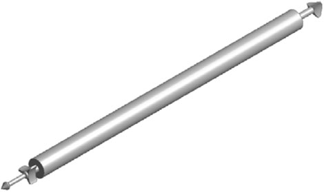
FIGURE 1. Standard fuel element.
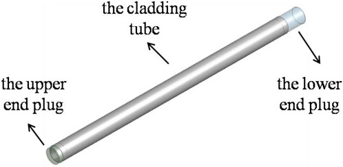
FIGURE 2. Simplified model of fuel element.
XAPR core contains fuel elements, control rods, neutron source elements, graphite elements, stainless steel ash body elements, and so on. The total number is about 198. The upper and lower grid plates of the core barrel are distributed with element holes to provide positioning and support for the elements. It can be seen that the core structure of XAPR is complex and there are many kinds of components. If a complete core geometry model is established, the model is too complex, the meshing is difficult and it is not realistic to calculate and solve. In order to simplify the problem, In this paper, according to the characteristics of fuel elements symmetrical layout in XAPR core, a geometric model is established by selecting local region. The geometric model of single/multi-fuel element and coolant has been established in order to analyze the fluid structure interaction between single/multi-fuel element and coolant. Firstly, make preliminary unidirectional fluid structure interaction analysis with 3 different geometric models, which contain 1, 2, and 4 fuel elements respectively; Secondly, analyze the influence of the number of fuel elements contained in the model on the calculation results; Thirdly, select the most suitable one from the 3 different geometric models, and then refine the model; Fourthly, make further unidirectional and bidirectional fluid structure interaction analysis with the selected model.
The fuel element in the core of XAPR is arranged in an equilateral triangle, as in Figure 3, the distance between the center line of the adjacent two fuel elements is 43 mm, the diameter of the fuel element is 37.2 mm, and the channel width between the adjacent two fuel elements is only 5.8 mm at the narrowest point. According to the symmetry, geometric model can be established by selecting local regions rather than intact cores. In Figure 3, the region within the rectangle frame (43 mm in width) is an option based on symmetry. The region consists of 2 intact fuel elements, 2 1/2 fuel elements and 4 1/4 fuel elements. On this basis, the number of fuel elements can be reduced further, and three geometric models are established: single element model, two elements model and four elements model, as shown in Figure 4 ∼ Figure 6. In Figure 4, there is only one fuel element along the flow direction located in the center of the water region, and the model does not take into account the influence of the fuel element around it on the calculation results; In Figure 5, there are two fuel elements along the flow direction, and the distance between the axis of them is 43 mm. The model only considers the influence of the adjacent fuel element along the flow direction. In Figure 6, there are four fuel elements, two of which are intact, and the distance between the axis of them is 74.48 mm, and the other two are selected only 1/2 according to symmetry, and the distance between the axis of them is 43 mm. The model considers the influence of adjacent fuel elements along the flow direction and in the lateral direction on the calculation results. In all three models, the upper and lower end plugs of the fuel element are simplified into cylinders. The water region sizes of the three models are 200 mm × 43 mm × 614 mm. The fuel element components that exposed to the outside and interact with the water flow include the upper and lower end plugs and the cladding tube which is the most fragile, so this paper focuses on the deformation of the cladding tube under the action of water flow, so the water region is 614 mm in depth, the same length as the cladding tube.
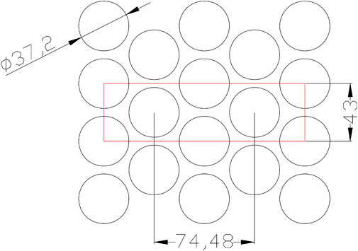
FIGURE 3. Schematic of local region of the core of XAPR.
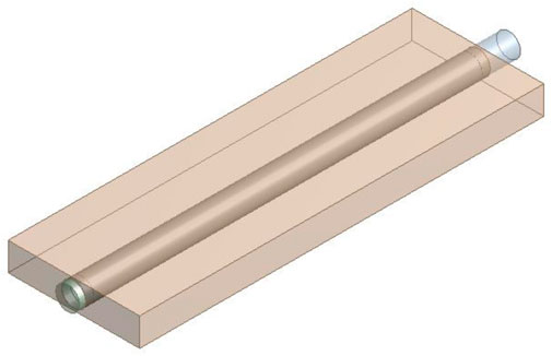
FIGURE 4. Single element model.
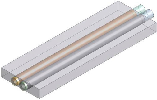
FIGURE 5. Two elements model.
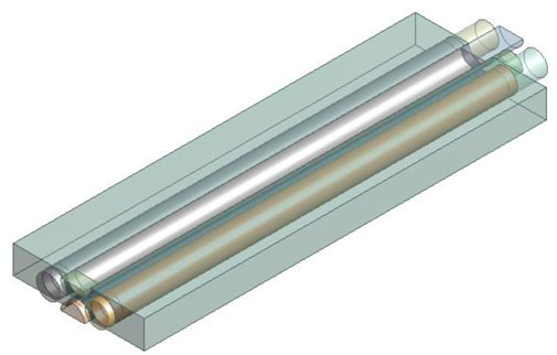
FIGURE 6. Four elements model.
According to the “Investigation Report on Seismic Intensity and Activity Fault of Xi ’an Pulsed Reactor Site,” the basic seismic intensity of XAPR site is VIII degree. The maximum impact intensity of historical earthquakes is set to IX degree. According to the relevant design documents, the designed seismic intensity of XAPR site is set to IX degree. Corresponding to this designed intensity level, the design acceleration value of the hard bearing layer is:
For Class III subsoil, the magnification coefficient of the formation covering the hard bearing layer γ = 1.5. Therefore, the design value of the ground acceleration ag is determined by the Formula 8:
in (8), g is gravitational acceleration, the value is 9.8 m/s2, so ag = 2.205 m/s2.
When the seismic intensity is Ⅸ degree, the peak velocity of ground motion in the horizontal direction is about 0.50 m/s (Zhao, 2012). It can be deduced that the peak relative velocity between coolant and fuel elements is about 0.5 m/s, so the inlet velocity is set to 0.5 m/s in the model. The boundary condition type of the outlet in the model is set to “open,” and the relative pressure is set to 0 Pa; Two sides are defined as symmetrical boundaries. The pressure distribution in the fluid domain is calculated first, and the fluid dynamics analysis results are used as the load transferred to the structural analysis modules, and fixed constraints are added to the two ends of the fuel element to calculate the stress and strain in the fuel element. The results are shown in Table 1.
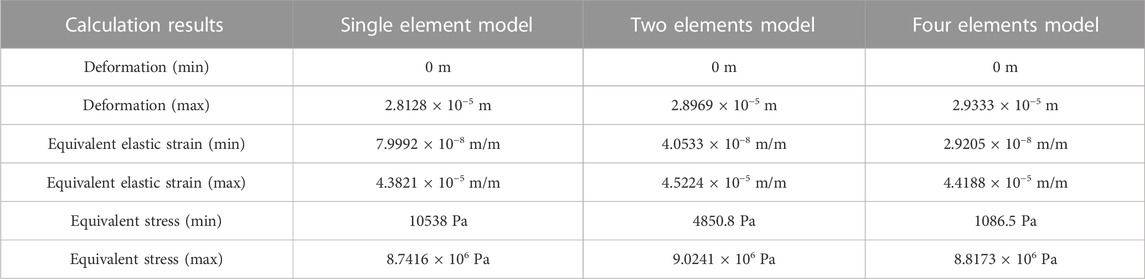
TABLE 1. Comparison between the results of the three models.
As shown in Table 1, the maximum deformation, equivalent elastic strain and equivalent stress of fuel elements calculated by the three models are very close to each other, and the maximum deviation is about 4%. Therefore, it can be concluded that the results obtained by the three models are in agreement with each other. Considering that the more components in the model, the larger the amount of computation, especially in the bidirectional fluid structure interaction analysis, the calculation process is time-consuming, so for the sake of simplicity, the single element model is chosen, and the geometric model is refined, to do further fluid structure interaction analysis.
Using a more accurate fuel element model and adding a water region around it, the model shown in Figure 7 is established as follows. The water region size is 74.48 mm × 43 mm × 614 mm.
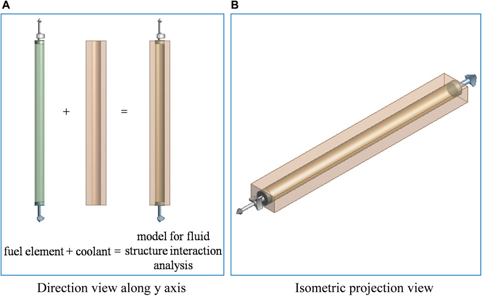
FIGURE 7. Fluid structure interaction analysis model. (A) Direction view along y axis. (B) Isometric projection view.
To analyze the impact of water region size on the calculation results, water region size is designed as x × 43 mm × 614 mm, and the parameter x takes values of 50, 100, 200, 300 mm, respectively. The inlet velocity is set to 0.5 m/s in the model. The boundary condition type of the outlet in the model is set to “open,” and the relative pressure is set to 0 Pa; Two sides are defined as symmetrical boundaries. The calculation results of the pressure of the water flow on the cladding tube per unit length are shown in Table 2. The parameter F represents the pressure of the water flow on the cladding tube per unit length. It can be seen that the parameter F is basically unchanged when the water region size parameter x varies from 50 mm to 300 mm.
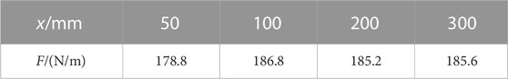
TABLE 2. The calculation results of the pressure of the water flow on the cladding tube.
The deformation of the fuel element cladding tube is directly related to the action of water flow on it. The force put on the fuel element cladding tube by water flow is calculated under different grid size conditions. In order to simplify the question, a two-dimensional model was chosen for grid sensitivity analysis. According to the symmetry, half of the region is selected as the computation domain. The geometric model is shown in Figure 8.

FIGURE 8. Geometric model for sensitivity analysis of the grid size.
The geometric model is meshed with different grid sizes, and the calculation results obtained by using these meshes are shown in Table 3. It can be seen that the grid independent solution is basically reached when the grid size is 5 × 10⁻⁴ m. Therefore, the grid size of 5 × 10⁻⁴ m is selected in the subsequent analyses and calculations.
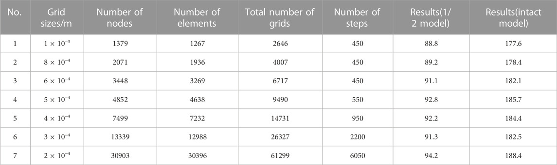
TABLE 3. The calculation results of the pressure of the sensitivity analysis of the grid size.
The inlet velocity is set to 0.5 m/s and the exit is set to open boundary. The rest of the wall is defined as a symmetric boundary. The results are shown in Figure 9–Figure 11.
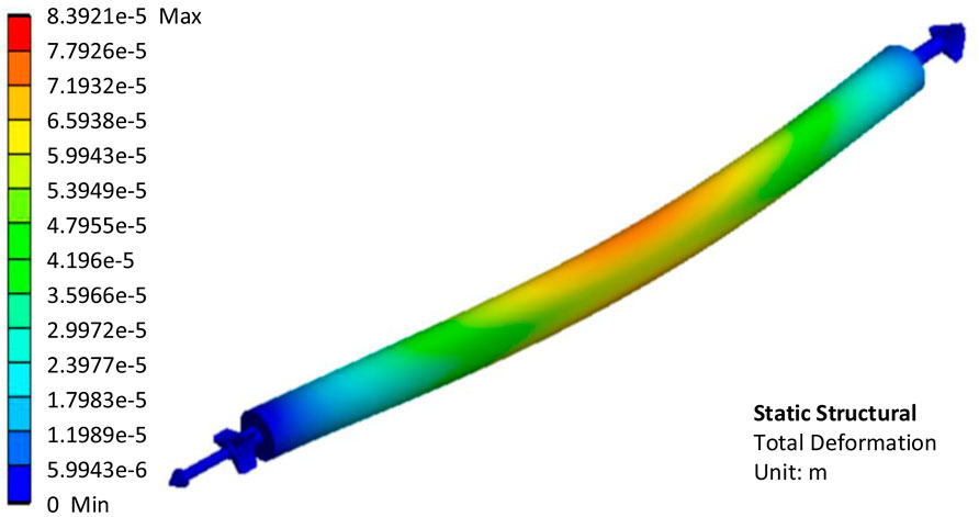
FIGURE 9. Calculation results of deformation of the fuel element in unidirectional fluid structure interaction analysis.
The fuel element cladding tube is pressed because of the maximum fluid pressure in the incoming flow direction. On both sides, the fluid pressure reaches a minimum, and the fuel element cladding is stretched to both sides. As can be seen in Figure 9, the maximum deformation of the fuel element is located approximately in the middle part. The maximum deformation is 8.3921 × 10⁻⁵ m, less than 0.1 mm. The fuel element has a diameter of 37.2 mm and a length of 760.5 mm. In contrast, the deformation of less than 0.1 mm is completely negligible. As shown in Figure 10, the maximum equivalent elastic strain of the fuel element cladding tube is 8.5799e-5 m/m, which is very small. The higher the temperature, the less tensile strength and yield strength of stainless steel. The maximum temperature of XAPR fuel element cladding under steady state operation conditions is 153.6°C (Northwest Institute of Nuclear Technology, 2000). At this temperature, the tensile strength of stainless steel is about 4.55 × 10⁸ Pa and the yield strength is about 1.59 × 10⁸ Pa (Assembly Preparation Team, 1975). As can be seen in Figure 11, the maximum equivalent stress in the fuel element cladding tube is about 1.57 × 10⁷ Pa, which is much less than the tensile strength and yield strength of the material, so it can be concluded that the fuel element cladding tube will not be damaged, and there will not be an unrecoverable deformation.
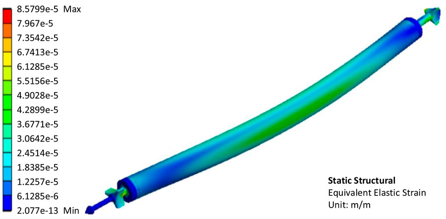
FIGURE 10. Calculation results of equivalent elastic strain of the fuel element in unidirectional fluid structure interaction analysis.
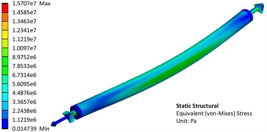
FIGURE 11. Calculation results of equivalent stress of the fuel element in unidirectional fluid structure interaction analysis.
Because of the lack of seismic data, the relation between displacement of the fuel element, s, and time, t, is assumed to be sinusoidal as Formula 9 for the sake of simplification:
The velocity, v, and acceleration, a, of the fuel element in the vibration during a seismic are respectively:
Taking into account that the acceleration of the ground ag = 2.205 m/s2, the period is 0.4 s (Li, 2002), it can be deduced that:
It can be calculated that ω ≈ 15.7 rad/s, A≈0.00894 m, so there is a Eq. 13:
The geometric model established for bidirectional fluid structure interaction analysis is the same as that used in unidirectional fluid structure interaction analysis, but the specific setting in the software is very different. The constraint condition about the displacement of the fuel element as shown in Eq. 13 is used in the calculation, the fluid structure interface is set reasonably by selecting the correct interface between the fuel element and the coolant, and the simulation time is set to a period of 0.4 s.
Calculation results show that deformation in x, y, and z direction are the largest when t = 0.08 s, the values are 3 × 10⁻⁵ m, 5.8036 × 10⁻⁷ m, and 4.8929 × 10⁻⁶ m, respectively. So the deformation in the x direction (along the flow direction) is most important, which is consistent with the fact. The maximum deformation is only 0.03 mm, which can be ignored. The equivalent elastic strain and equivalent stress are also obtained when t = 0.08 s, which are 2.3152 × 10⁻⁴ m/m, 4.4683 × 10⁷ Pa, respectively. The equivalent stress is less than the tensile strength and yield strength of the material, so it can be concluded that the fuel element cladding tube will not be damaged, and there will not be an unrecoverable deformation.
The results show that the fluid structure interaction between the coolant and the fuel element in XAPR is very weak and negligible under the seismic conditions set in this paper.
In this paper, first, assume that there is no deformation in the solid component (fuel element). According to the geometric symmetry, the local region in the core is selected to establish the model and carry out the fluid flow analysis. The inlet boundary condition is velocity inlet, the outlet boundary condition is pressure outlet, and the rest is symmetric boundary. By solving the hydrodynamic equation, the coolant pressure distribution on the cladding surface of fuel element is obtained. Then the structural analysis is made for the fuel element cladding, the pressure distribution on the cladding surface is taken as the boundary condition, the elastic modulus, Poisson’s ratio and other parameters of the material are set, and the constraint conditions are put on the contact surfaces between the fuel element cladding and the upper and lower grid plates, and the deformation and internal stress distribution of the cladding are obtained. According to the deformation of the fuel element cladding, the fluid domain in the geometric model is modified, and the fluid flow analysis is carried out again, and the coolant pressure distribution on the fuel element cladding surface is obtained, and then the structural analysis is carried out again. So iterate until the final convergence solution is obtained. In the process of solution, it is necessary to ensure that the pressure load can be transferred correctly at the interface of fluid and solid domain, and that the nodes in fluid and solid domain should be consistent at the interface.
It can be concluded that the fluid structure interaction between the fuel element cladding tube and the coolant in XAPR results in the deformation of the fuel element cladding tube under the action of the horizontal acceleration. The size of the deformation is related to the additional pressure applied by the coolant to the cladding tube and the tensile strength and yield strength of the cladding tube material. The pressure is related to the magnitude of the horizontal acceleration, coolant density, fuel element layout and other factors. The tensile strength and yield strength of cladding tube materials are related to the material type and temperature. An acceptable deformation should be within the elastic deformation range, in which case the cladding tube can be restored to its original state when the additional pressure applied by the coolant to the cladding tube is removed. When the seismic intensity is higher, resulting in greater horizontal acceleration, or when the reactor is in an accident state, such as large-break LOCA, the cladding tube has a higher temperature and its strength decreases, which can lead to significant deformation.
The geometric model of single/multi-fuel element and coolant is established based on that the upper and lower end plugs of fuel element in the core of XAPR are simplified into cylinders. The fluid structure interaction between single/multi-fuel element and coolant is studied with the finite element method. The effect of the number of fuel elements on calculation results is analyzed by comparing the results obtained from the three different geometric models. It can be seen that the results are basically in agreement with each other. For the sake of simplicity, the single fuel element model is selected and the fuel element model is refined properly. Under the given seismic conditions, unidirectional and bidirectional fluid structure interaction analysis between the fuel element and coolant are carried out, and the internal stress and strain distribution in the fuel element cladding tube are obtained, and some conclusions can be made as follow.
(1) The effect of the number of fuel elements in the model on the calculation result is slight in the fluid structure interaction analysis for XAPR under the given seismic conditions;
(2) The maximum equivalent stress in the fuel element cladding tube is much less than the tensile strength of the material, so the fuel element cladding tube will not be damaged or fractured;
(3) The maximum equivalent stress in the fuel element cladding tube is much less than the yield strength of the material, so there will not be an unrecoverable deformation;
(4) The deformation of the fuel element cladding tube is very small, less than 0.1 mm.
It can be concluded that the fluid structure interaction between the fuel element and the coolant in XAPR core is very weak under the seismic conditions set in this paper, and it will not pose a threat to the safety of XAPR, so it can be neglected.
The original contributions presented in the study are included in the article/Supplementary material, further inquiries can be directed to the corresponding author.
All authors listed have made a substantial, direct, and intellectual contribution to the work and approved it for publication.
The authors declare that the research was conducted in the absence of any commercial or financial relationships that could be construed as a potential conflict of interest.
All claims expressed in this article are solely those of the authors and do not necessarily represent those of their affiliated organizations, or those of the publisher, the editors and the reviewers. Any product that may be evaluated in this article, or claim that may be made by its manufacturer, is not guaranteed or endorsed by the publisher.
Assembly Preparation Team (1975). Nuclear reactor material performance data assembly. Beijing: Atomic Energy Publishing House, 199.
Bao, G. (2019). The numerical study on sloshing liquid in fast reactor vessel considering fluid-structure interaction. Beijing: School of Nuclear Science and Engineering of North China Electric Power University, 7.
Cao, G., Zhu, He, and Ye, X. (2021). Analysis of three-dimensional nonlinear impact on reactor structure. Nucl. Power Eng. 42 (1), 70–74. doi:10.13832/j.jnpe.2021.01.0070
Chen, X., Yuan, D., and Yang, M. (2010). Blade stress of the reactor coolant pump of 300 MWe nuclear power plant in China based on fluid-solid coupling method. J. Mech. Eng. 46 (4), 112. doi:10.3901/JME.2010.04.111
Christon, M. A., Lu, R., Bakosi, J., Nadiga, B. T., Karoutas, Z., and Berndt, M. (2016). Large-eddy simulation, fuel rod vibration and grid-to-rod fretting in pressurized water reactors. J. Comput. Phys. 322, 142–161. doi:10.1016/j.jcp.2016.06.042
Deng, Y., Wu, Y., Qiu, B., Zhang, D., Wang, M., Tian, W., et al. (2017). Development of a new pellet-clad mechanical interaction (PCMI) model and its application in ATFs. Ann. Nucl. Energy 104, 146–156. doi:10.1016/j.anucene.2017.02.022
Ding, L., He, H., and Yang, Z. (2021). Thermal-fluid-solid coupling characteristics of a circular tube in two degrees of freedom flow-induced vibration. Nucl. Power Eng. 42 (2), 131. doi:10.13832/j.jnpe.2021.02.0131
Li, C., Wu, Y., Wang, Y., Wang, K., Wang, M., Tian, W., et al. (2020). Analysis on the behavior of dispersed plate-type fuel based on fluid-solid coupling method. Prog. Nucl. Energy 126, 103398. doi:10.1016/j.pnucene.2020.103398
Li, S. (2002). Calculation of anti-seismic design for xi’an pulsed reactor. Nucl. Power Eng. 23 (6), 12–15.
Liao, H., Wang, Y., Li, Y., Wang, K., Deng, Y., Su, M., et al. (2020). 3D fluid-solid coupling simulation for plate-type nuclear fuel assemblies under the irradiation condition. Prog. Nucl. Energy 126, 103428. doi:10.1016/j.pnucene.2020.103428
Northwest Institute of Nuclear Technology (2000). Xi 'an pulsed reactor training textbook. Appendix-2 (Internal Information).
Qian, H., Xie, Y., and Zhang, K. (2011). Preliminary analysis of flow induced vibration for AP1000 secondary core support assembly. Nucl. Power Eng. 32 (1), 145–148.
Tang, D., Bao, S., Lv, B., Cui, H., Luo, L., and Xu, M. (2019). Investigation of shedding patterns and its influences on lift performances of a cylinder bundle in cross flow. J. Mech. Sci. Technol. 33 (6), 2651–2663. doi:10.1007/s12206-019-0513-9
Wang, M., Bai, L., Wang, L., Qiu, S., Tian, W., and Su, G. (2017). Thermal hydraulic and stress coupling analysis for AP1000 Pressurized Thermal Shock (PTS) study under SBLOCA scenario. Appl. Therm. Eng. 122, 158–170. doi:10.1016/j.applthermaleng.2017.04.106
Wang, M., Fang, Di, Xiang, Y., Fei, Y., Wang, Y., Ren, W., et al. (2018). Study on the coolant mixing phenomenon in a 45° T junction based on the thermal-mechanical coupling method. Appl. Therm. Eng. 144, 600–613. doi:10.1016/j.applthermaleng.2018.08.073
Wang, M., Wang, Y., Tian, W., Qiu, S., and Su, G. (2021). Recent progress of CFD applications in PWR thermal hydraulics study and future directions. Ann. Nucl. Energy 150, 107836. doi:10.1016/j.anucene.2020.107836
Wang, Y., Wang, M., Jia, K., Tian, W., Qiu, S., and Su, G. (2022). Thermal fatigue analysis of structures subjected to liquid metal jets at different temperatures in the Gen-IV nuclear energy system. Energy 256, 124681. doi:10.1016/j.energy.2022.124681
Xu, J., Liu, L., and Yu, D. (2016). Research of flow induced vibration test for CAP1400 reactor internals. Nucl. Power Eng. 37 (2), 40–43.
Yang, J., Xi, Z., and Yu, D. (2016). Study on flow induced vibration in reactor internals of HPR1000. Nucl. Power Eng. 37 (S2), 37–39.
Ye, Q., Yu, D., and Fang, X. (2003). Flow induced vibration test for reactor internals for qinshan phase II NPP project. Nucl. Power Eng. 24 (1), 87–90.
Yu, D., Ma, J., and Xi, Z. (2016). Review of experimental research of flow-induced vibration of reactor internals. Nucl. Power Eng. 37 (2), 47.
Zang, F., and Liu, W. (2005). Flow induced vibration analysis of thermo-well at main pipe of reactor coolant loop. Nucl. Power Eng. 26 (4), 360–362.
Keywords: XAPR, fluid structure interaction, finite element analysis, seismic, deformation
Citation: Hu P, Ma Z, Ma T, Wang B, Tang X, Su C, Yang N and Chen L (2023) Analysis of fluid structure interaction between fuel elements and the coolant in Xi’an Pulsed Reactor core under seismic conditions. Front. Energy Res. 11:1028079. doi: 10.3389/fenrg.2023.1028079
Received: 25 August 2022; Accepted: 25 October 2023;
Published: 09 November 2023.
Edited by:
Qingming He, Xi’an Jiaotong University, ChinaReviewed by:
Mingjun Wang, Xi’an Jiaotong University, ChinaCopyright © 2023 Hu, Ma, Ma, Wang, Tang, Su, Yang and Chen. This is an open-access article distributed under the terms of the Creative Commons Attribution License (CC BY). The use, distribution or reproduction in other forums is permitted, provided the original author(s) and the copyright owner(s) are credited and that the original publication in this journal is cited, in accordance with accepted academic practice. No use, distribution or reproduction is permitted which does not comply with these terms.
*Correspondence: Lixin Chen, Y2hlbmxpeGluQG5pbnQuYWMuY24=
Disclaimer: All claims expressed in this article are solely those of the authors and do not necessarily represent those of their affiliated organizations, or those of the publisher, the editors and the reviewers. Any product that may be evaluated in this article or claim that may be made by its manufacturer is not guaranteed or endorsed by the publisher.
Research integrity at Frontiers
Learn more about the work of our research integrity team to safeguard the quality of each article we publish.