 Ming Li
 Wenbo Ren
 Anqing Chen*
 Jiayuan Gong
- Hubei University of Automotive Technology, Shiyan, China
In order to make the power transmission more stable and ensure the safe operation of the system, a study on the interaction of controllable series compensation and traditional PSS to suppress low-frequency oscillation is proposed. Firstly, the lead-slip angle is adjusted by the lead-lag module of the PSS limit stabilizer to eliminate the reverse modulation phenomenon, and the series compensation is used to optimize the parallel transmission lines and lines of different voltage levels to improve the stability of the long-distance transmission system. Secondly, the phase compensation method is used to set the parameters of the TCSC and PSS damping controllers, the characteristics of the rotor system are judged by the damping ratio, the sensitivity characteristic root is extracted, and the maximum parameters affecting the mode are determined; finally, the genetic algorithm is introduced to coordinate the damping controller to increase the oscillation. Mode damping, constraining the range of each tuning parameter, enabling coordinated optimization. Experiments show that the method in this paper can effectively suppress low-frequency oscillation and ensure the safety and stability of the power system.
1 Introduction
With the continuous development of State Grid in Wanlian and West-to-East Power Transmission Project areas, the scale and complexity of modern power systems are increasing day by day. In particular, the large-scale application of new technology equipment such as fast excitation systems has led to an increase in the low frequency oscillation frequency of the system. In view of the harm of low-frequency oscillation to system stability, relevant personnel at home and abroad have done a lot of research work on low-frequency oscillation, mainly focusing on the generation mechanism and suppression measures of low-frequency oscillation. Power system stabilizer is a measure to suppress the occurrence of low frequency oscillation, and its design idea is largely influenced by the mechanism of low frequency oscillation.
In the FACTS technology, Thyristor Controlled Series Compensation (TCSC) can flexibly and continuously adjust the compensation capacity and the normal order impedance of the line. The TCSC is an effective means to control the power flow and stability of the power grid (Chen et al., 1996). By appropriately adjusting the compensation amount, the TCSC can increase the damping of the system (Dolan et al., 1995; Wang F and Swift, 1997; Del Rosso et al., 2003). For the effective damping power oscillation, the appropriate damping control strategy needs to be adopted, and the determination of the damping control strategy needs to study the mechanism of the damping oscillation in the FACTS device.
Since the 1960s, oscillation accidents have occurred in many international power grids (including China’s power grids), resulting in difficulty in system operation and major power grid accidents caused by oscillations (Investigation Team of Power System Safety and Stability Control and Ministry of Electric Power, 1998). The phenomenon is that the frequency or power with a certain amplitude swings regularly on the transmission line. If the swing amplitude increases and diverges gradually, the system must not be discontinuous. Traditional damping methods based on local signals, such as Power System Stabilizer (PSS) (Fang and Zhu, 1994); (Liu and Fang, 1998); (Wu and Han, 1996); (Trudnowski et al., 1992), can well suppress the oscillations in the region, but sometimes the oscillation modes between regions are not equal. Not enough shock absorption.
Reference (Xu et al., 2004) analyzes the system structure and working principle of damping low-frequency oscillation of TCSC device from the aspect of engineering application, determines the selection principle of damping control input, and conducts dynamic model experiments with or without power oscillation damping to verify the results. The effect of TCSC damping low frequency oscillations. Reference (Zhou, 1993) analyzes the theory of power system damping enhancement by applying static var compensator (SVC). The impact of SVC on power systems, how to control SVC to improve system damping, and the difference between continuous and discontinuous control of SVC reactive power for maximum damping improvement. Reference (Lerch et al., 1991) proposed a novel SVC (Static Reactive Power Compensation) control method for suppressing power system oscillations. To increase system damping, the SVC uses a phase angle signal estimated by measuring the voltage and power at the SVC position. Through optimization and identification procedures, the optimal design of damping control with various control concepts can be determined, considering nonlinear power systems. In the literature (Sun and Liu, 1999), based on the Phillips-Heffron model established for the power system, this paper studies the application of the controllable series compensator (CSC) in damping the oscillation of the power system. The ability of CSC damping control to provide damping for power system is analyzed for its damping torque contribution to single-machine infinite bus and multi-machine power system. In summary, the literature uses a method to suppress power oscillation, and the effect is general, and it is necessary to propose a better control method. Therefore, this paper proposes a research on the interaction of controllable series compensation and traditional PSS to suppress low-frequency oscillation. The low frequency oscillation in the circuit is suppressed by adding PSS to the power system, the state equations of PSS and TCSC single-machine infinite system and multi-machine system are established, the oscillation mode is analyzed through spatial eigenvalues, and the sensitivity filter installation is analyzed through sensitivity analysis location (Swift and Wang, 1996) (Chen, 2004).
2 PSS model and controllable series compensation (TCSC) principle and modeling
2.1 PSS model development
The input signal adopted by PSS is one or a combination of several signals among rotational speed deviation
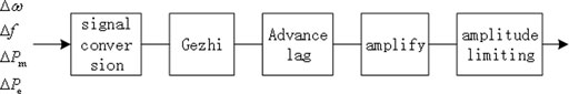
FIGURE 1. PSS block diagram.

FIGURE 2. PSS general transfer function.
In the development history of PSS, its mathematical model has experienced the evolution process from single-input PSS, dual-input PSS to multi-band PSS. According to the IEEE Std 421.5-2005 standard revised by the IEEE Excitation System Committee, the mathematical model of PSS is divided into PSS1A and PSS2B.
PSSIA is a single-input PSS, and its mathematical model is shown in Figure 3. The first module is used to represent the inertia in signal measurement, the second module is used to block DC, and the third module is used to change the frequency characteristics of the stabilizer or To filter the components of shafting torsional oscillation, the fourth and fifth modules are two-stage lead and one lag, which are used to adjust the lead-slip angle of the tuning stabilizer. Its input signal is generally the electrical power of the generator, which first passes through the DC blocking link, and then performs lead-lag processing to achieve the purpose of suppressing low-frequency oscillation. PSS1A has a simple structure, and has a good suppression effect on low-frequency oscillation in the frequency range of 0.1–2.5 Hz, but at the same time, there will be a reverse modulation phenomenon (that is, when the input power of the prime mover of the unit is increased, the reactive power of the generator will appear relatively large. And it is not allowed to decrease, but when the input power of the prime mover is reduced, the reactive power of the generator will appear relatively large and cannot be allowed to increase), especially in some units that can quickly adjust the active power. The phenomenon of reverse modulation is particularly serious when the PSS is used, such as hydroelectric generator sets and gas-fired generator sets.
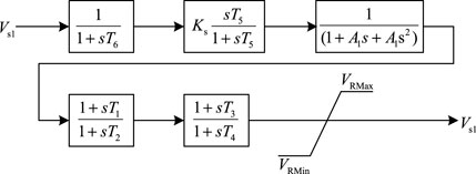
FIGURE 3. PSS1A mathematical model.
PSS2B is a dual-input PSS, and its mathematical model is shown in Figure 4. The two limiters added to the input are used to limit the working range of the stabilizer; the latter three-stage lead and one lag module make the phase compensation more flexible. Its input signals are mainly generator speed and electric power, which are first combined into an integral signal of acceleration power (that is, the difference between prime mover power and electric power), and then sent to the stabilizer through the lead-lag module. This kind of stabilizer has the advantages of easy implementation and low noise, and can effectively avoid the fluctuation of reactive power caused by the rapid change of active power, and can better eliminate the phenomenon of reverse modulation, so it is widely used. However, PSS2B is a single-branch structure, and its damping effect is not good for multiple oscillation modes at the same time.
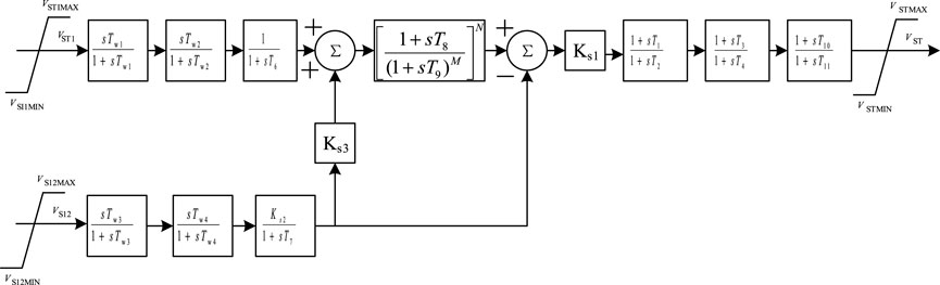
FIGURE 4. PSS2B mathematical model.
2.2 Series capacitance compensation of transmission lines with controlled series compensation
Series compensation can optimize the power flow of parallel transmission lines and lines with different voltage levels, and improve the transmission capacity and system stability of long-distance transmission systems (Larsen et al., 1994); (Li, 2022b). As shown in Figure 5, when the capacitors are fixed in series on Line 1-3, the transmission power of this line rises from 1400 to 1750 MW, which makes the adjacent Lines 1-2 and 2-3 withstand smaller transmission capacity. The size and direction of the power flow can be changed by connecting capacitors in series, and part of the active power can be transferred to the heavy-load line in time to reduce the chance of system instability.
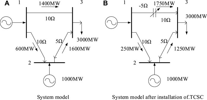
FIGURE 5. The effect of series compensation on improving the transmission power of the line. (A) System model. (B) System model after installation of TCSC
The traditional fixed series compensation cannot flexibly adjust the line parameters, and it is easy to cause subsynchronous resonance, which greatly limits the compensation ability of the fixed series compensation. In practical applications, it is not allowed to turn off the capacitor in the event of a fault, so as not to cause the above-mentioned harm to the system. Therefore, it cannot be put into operation when capacitor series compensation is most needed to improve system dynamic performance.
However, if the traditional mechanical switch is replaced by a thyristor, when the system is disturbed, the thyristor can be used to switch the capacitor to quickly compensate the line, thereby suppressing the power oscillation of the system (Zhao and Jiang, 1998). Therefore, the thyristor-controlled capacitance compensation device naturally emerges as the times require.
3 Interaction analysis of low frequency oscillation
3.1 Method introduction
In this paper, the transfer function model of the single-machine infinite system is studied, and the multi-machine systems of TCSC and PSS are respectively established (Larsen and Swann, 1981a); (Larsen and Swann, 1981b); (Heffron and Phillips, 1952), and the specific form of the additional torque provided by TCSC and PSS is deduced by using the concept of electric torque., the damping controller model is introduced. Using the stability analysis of small disturbances, from the perspective of eigenvalues (Martins and Lima, 1990), the modal analysis method was used to study the suppression effect of TCSC and PSS interaction on low frequency oscillation, which provided a basis for parameter tuning of TCSC damping controller.
Modal analysis is the analysis of each mode in the system (Li et al., 2021a). It is pointed out that the slight disturbance in the system may cause the oscillation of the state quantity in the system, which is called the inherent characteristic of the power system. The oscillation of the state quantity is related to the electromechanical oscillation mode, subsynchronous resonance (Li et al., 2021b) and the controller oscillation mode. The most serious impact on the generator is the electromechanical oscillation mode, which may cause the generator rotor to vibrate strongly and damage the generator rotor main shaft. Introduction of PSS stabilizer to suppress electromechanical oscillation modes Through modal analysis, participation factors can be calculated from eigenvalues, thereby extracting electromechanical oscillation modes. By calculating the relative factors of angular velocity and angle of attack on the electromechanical oscillation mode, the sensitivity of the mechanical damping change of the motor shaft under a certain electromechanical oscillation mode can be determined. The sensitivity represents the damping effect of the PSS mounted on the generator in this mode. If the participation coefficient of this mode to the generator speed or power angle component is large and positive, it means that if PSS is installed on the generator, the oscillation mode can be well suppressed, so PSS should be installed on the generator (Larsen and Swann, 1981d); (Larsen and Swann, 1981c).
3.2 Electromechanical oscillation mode extraction and damping ratio calculation
This paper mainly adopts the state space characteristic root analysis method to study the oscillation mode of the system and extract the electromechanical oscillation mode. The role of PSS and the choice of installation site are studied through eigenroot sensitivity analysis (Sun and Liu, 1999), and the parameters of TCSC and PSS damping controllers are set through phase compensation method (De Mello and Concordia, 1969); (De MelloP et al., 1980). Finally, the changes of the mechanical and electrical vibration modes of the system before and after the installation of the TCSC and PSS controllers are illustrated, and the suppression effects of the TCSC and PSS on low-frequency oscillation are verified.
The characteristic root of the A matrix is the characteristic root of the system, and the stability of the system can be judged by the distribution of the characteristic root on the complex plane. Of all the eigenvalues, some are determined by the rotor’s equation of motion, and these oscillation modes are called rotor swing modes or electromechanical modes. In this paper, the suppression of electromechanical oscillation modes by PSS devices is considered. Therefore, we only need to extract the eigenvalues of the rotor swing pattern and study it.
When judging whether the characteristic root is the rotor swing mode, it is necessary to calculate the coefficient K1 (Wang and Swift, 1997); (Wang et al., 1998) according to the whole system transfer function block diagram (Phillips-Heffron model), then calculate the undamped natural oscillation angular frequency, and then determine which frequency of ωn Approach the eigenroot (imaginary part of the eigenroot). It is then listed as rotor swing mode.
In electromechanical mode
The system damping characteristics of the rotor can be calculated and can be judged by the damping ratio.
3.3 Damping of the main vibration mode of the system under different operating modes
3.3.1 Relevant factors
The physical quantity
In the formula:
3.3.2 Sensitivity of eigenroots to parameter changes
When a system parameter (eg)
The system matrix is A (
If both sides of the equation are multiplied to the left by
In formula (3),
By calculating the sensitivity of the eigenroot, the influence of the parameters on the eigenroot can be quantitatively compared (Perez-Arriaga et al., 1982). For example, the sensitivities of different eigenvalues to TCSC controller parameters (such as the amplification factor of the inertial link) can be compared to determine which element or elements have the greatest influence, or the sensitivity of a certain element. Eigen roots of different parameters in the same element can be compared to determine which parameter has the most influence on the mode.
4 Coordinated design of damping controller based on improved genetic algorithm
This paper adopts the fitness evaluation of the improved genetic algorithm based on sensitivity, which can greatly speed up the evaluation and selection process, reduce the amount of calculation, and improve the efficiency. The combination of sensitivity and genetic algorithm can improve the convergence speed.
When tuning parameters of large-scale power grids, the calculation of fitness will take a long time because the dimension of the system state matrix (Wang et al., 1998) is too high. If each genetic operator operation is performed randomly, the genetic algorithm will be difficult to converge. Based on eigenvalue analysis, genetic operator operations are carried out on the tuning parameters according to the sensitivity of the eigenvalues, which accelerates the convergence speed of the genetic algorithm. Before the genetic operator operation is performed, the sensitivity of the eigenvalue is calculated first, and the sensitivity matrix is obtained. First, the sensitivity of the low-frequency oscillation mode with less damping is found. The sensitivity related to this oscillation mode is the first row. The element of is the column, then it can be determined that the size of the element has the greatest influence on the damping of this oscillation mode, and then according to the positive or negative of the sensitivity (Perez-Arriaga et al., 1982); (Li, 2022a), it is decided whether to increase or decrease the value of this parameter to increase the damping of this oscillation mode. Finally, find the position of the parameter in the chromosome and change the number.
The objective function of the coordinated control with the parameters of the damping controller can be set as x, which is the number of weak damping operation modes, and the number of key oscillation modes,
The flow based on the sensitivity genetic algorithm is described in detail below, and the specific flow chart is shown in Figure 6. Each step is explained in detail as follows:
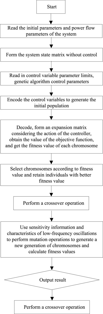
FIGURE 6. Flow chart of improved genetic algorithm.
First the program starts. Read the initial numerical control from the file, including network parameters (transmission line, transformer, load, power generation parameters, DC system parameters), power flow result data (voltage amplitude and phase angle of each node), generator parameters. Then, the formation method of the small disturbance linearization model is used to form the initial state matrix of the system when no control is added. Read in control variable parameter limits, genetic algorithm control parameters. Including the upper and lower limits of each controller’s magnification and time constant, the maximum number of iterations of the genetic algorithm, the population size, the crossover rate, the mutation rate and the optimal number of individuals to retain per generation. This article samples the encoding rules of decimal floating-point numbers, and each floating-point number in the chromosome represents a controller parameter to be optimized.
Start running the genetic algorithm and set the maximum genetic algebra to be gen, then all genetic operations in the future will be carried out in a large loop. Start decoding the data to form an expansion matrix that takes into account the role of the controller. Calculate the objective function value and get the fitness value of each chromosome. The best retention mechanism is adopted to select 5% of the best individuals in the population. This part of the individuals will not participate in crossover and mutation and will directly enter the next generation. This is to prevent the excellent individuals from being randomly crossed and mutated. Changed and lost. Then carry out the selection of fitness value. Through the survival competition mechanism given in this paper, the chromosome schemes in the group are compared, and the chromosome individuals with larger fitness value are retained, and the chromosome individuals with smaller fitness value are eliminated, which is equivalent to Selected individuals from the original population form a new population. The selected individuals are sent to the crossover library. Perform random crossover operations on individuals that need to be crossed. This step plays a role in expanding the search range of the genetic algorithm. Through crossover, it is possible to generate better individuals than all previous individuals.
The sensitivity information is then used to guide the mutation operation, in order to further expand the search range of the solution and avoid falling into the local search situation. The new population formed by finishing is the second generation of genetic evolution. To judge whether the convergence standard is met, this program combines the maximum genetic algebra and the optimal individual continuous retention algebra as the judgment basis. After the best individual is selected, the low-frequency oscillation analysis and calculation are performed on it separately to obtain parameters such as the relevant oscillation mode. The optimized parameters of each controller, the eigenvalues of the optimized low-frequency oscillation mode, and the damping ratio are displayed. End the algorithm operation process.
5 Experiments and experimental conclusion
According to the actual parameters of the UHV power supply system in a certain area, the simulation model is built in the PSASP simulation software. The voltage level of the high-voltage external transmission system in this area is 1000 kV. The transmission-end network is relatively centralized and has high power transmission. The ten generator sets are divided into four areas. Beijing and Jinan are powered by two power grids. The two power grids are represented by equivalent system 1 and equivalent system 2 respectively. The total transmission power of the two UHV lines reaches 7020 MW. The wiring diagram of the large power UHV transmission system in this area is shown in the Figure 7 is shown.
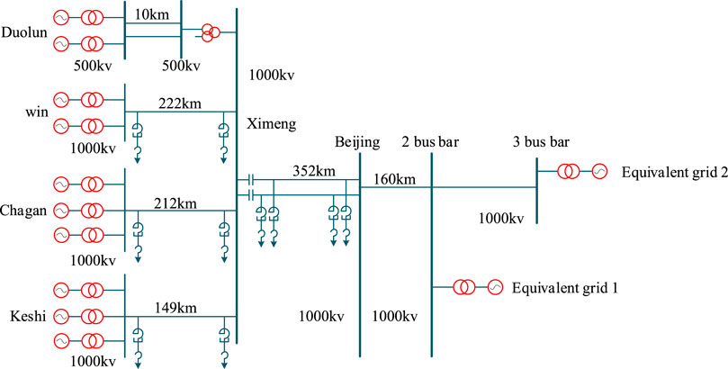
FIGURE 7. Wiring diagram.
A simulation experiment is designed to analyze the small disturbance of the simulation system. A single-phase short-circuit ground fault is applied at the head end of the transmission line. The fault start time is 5s, and the fault is removed after 0.1 s. The system is identified by the method of matrix number identification, and the active power of a tie line from the bus in this area to the Beijing bus is taken as the input of identification, which can well reflect the transient characteristics of the system. Table 8 shows the main oscillation modes of the system. Other oscillation modes have smaller amplitudes and better damping characteristics, and are not listed one by one in the table.
From the analysis in Table 8, the first two are the low-frequency oscillation modes in the region, and the last one is the interval low-frequency oscillation mode of the Ximeng sending-end region relative to the receiving-end system.
5.1 Design and effect verification of the controller
According to the analysis method in this paper, the PSS is used to control the oscillation mode between the two regions, and the TCSC damping controller is used to control the oscillation mode between the regions to achieve the purpose of enhancing the damping characteristics of the system.
Firstly, the TCSC damping controller is designed according to the interval oscillation mode of the system. Install the TCSC on two AC tie lines, and select the power change value of the corresponding AC tie line as the input signal of the TCSC damping controller. According to the residual analysis method, the required compensation phase can be obtained as 38°. The design of the device, the size is 5.356 rad/s. Set the limiter link to ±0.1 (pu). At the same time, it compares and analyzes the TCSC damping controller designed by the traditional residual analysis method, and observes the difference of the effects of the two controllers.
The transfer function of the TCSC damping controller designed by the residual analysis method is shown in the following formula, and the gain of the controller is considered to be 10, that is,
The transfer function of the controller designed according to the method in this paper is:
Table 1 shows the suppression effects of TCSC designed by various methods on each mode. From the data in Table 1, it can be seen that the TCSC damping controller designed according to the traditional method or the method in this paper can better The interval low frequency oscillation of the system is suppressed, but the former will also affect the oscillation modes in the region, because the controller has the effect of phase compensation for the oscillation modes in a large frequency range. As shown in Figure 8, it can be seen that the controller designed by the method in this paper has a better suppression effect on the interval low-frequency oscillation, but the corresponding oscillation modal damping does not increase proportionally with the increase of the gain, which is different from the controller’s Limiting link.
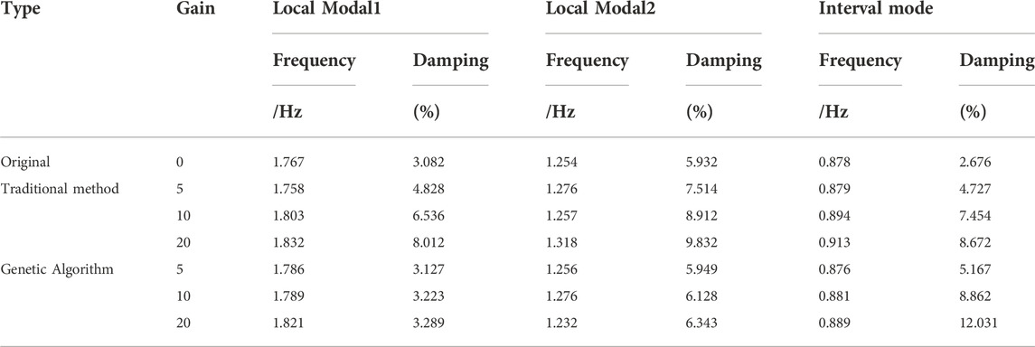
TABLE 1. Suppression effects of TCSCs designed by different methods on various modes.
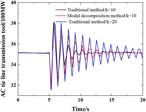
FIGURE 8. Power oscillations of AC tie lines with different controllers installed.
As can be seen from Figure 8, although the controller designed by the traditional method has a certain inhibitory effect on the main modes of the system, the overall effect is not as good as the controller designed by the traditional method because the controller designed by the traditional method interacts with other modes. Method to design the effect of the controller.
Secondly, the PSS is designed, which is similar to the design of the TCSC damping controller, but the PSS is designed on the basis of installing the TCSC damping controller. First, determine the main vibration units of the oscillation mode in the two regions, respectively install PSS on the engine, and select the rotor angular velocity difference of the corresponding two vibration units as the input signal of the PSS for the two PSS. By identifying the system and using the residual analysis method, the compensation phases of the two PSSs can be determined to be 24° and 51°, respectively. According to the oscillation frequencies of the modes in the two regions in Table 2, it can be known that the center frequencies of the corresponding filters are 11.135 rad/s and 7.945 rad/s respectively, and the quality factor of the filter is taken as 2, and the limiting link is set to ±0.1 (pu). Then the transfer functions of the two PSSs can be expressed as:

TABLE 2. Main oscillation modes of the system.
The damping characteristics of the system oscillation mode after installing two different controllers are shown in Table 3. It can be seen from the data in Table 3 that the PSS and TCSC damping controllers designed by the two methods can suppress the low-frequency oscillation of the system and improve the damping effect of the system. However, compared with the damping characteristics of the interval modes in Table 1, the interaction between the PSS and TCSC damping controllers designed by the traditional method is produced, which obviously reduces the damping effect of the controller on the interval oscillation modes. However, there is no interaction between the PSS and TCSC damping controllers designed one by one through the genetic algorithm, which can better improve the damping characteristics of the system.
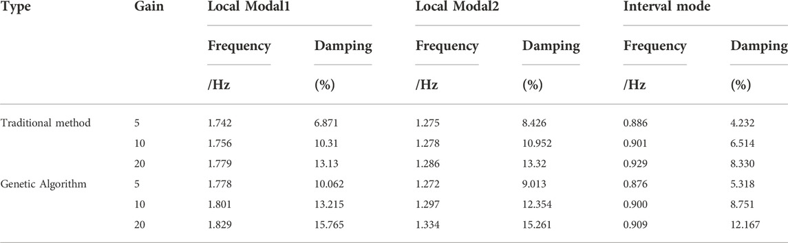
TABLE 3. Damping characteristics of system oscillation modes after installing two different controllers.
As shown in Figure 9, when the controller has the same gain, the controller designed by using the genetic algorithm can better suppress the oscillation of the system, the system tends to be stable faster, and with the increase of the magnification, the damping effect is also better. However, due to the limitation of the filter effect and the existence of the limiting link, when the gain reaches a certain value, the damping effect is also no longer linear with the gain.
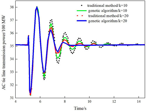
FIGURE 9. Oscillation of AC tie line when installing PSS and TCSC designed with different control methods.
5.2 Verification of robustness
In order to verify the robustness of the designed controller, the performance of the controller under different operating modes of the system is simulated and verified, and the gain of the controller is kept at 10. Consider the following modes of operation.
①Increase the power transmission power of the UHV power supply system to 7720 MW.
②The generator is out of operation.
③The system disconnects an AC tie line and N-1 operates.
As shown in Table 4, for the first two operating modes, the controller designed by this method can provide good damping effect. However, for the third operation mode, since a tie line is disconnected, which is equivalent to increasing the electrical distance of the system, the grid structure of the system has undergone great changes, the oscillation frequency is changed too much, and the controller damps the system. The effect is not as good as the first two modes of operation. However, the damping of the system can be improved by properly adjusting the quality factor of the filter and the center frequency of the bandpass.
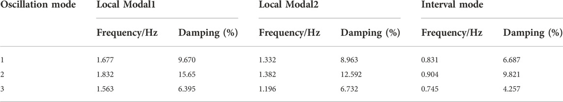
TABLE 4. Damping of the main vibration mode of the system under different operating modes.
6 Conclusion
In this paper, the genetic algorithm is used to optimize the controller for controlling the low frequency oscillation of the system. The idea of this method is to use different controllers to suppress different single oscillation modes, and there is no interaction between the controllers. The PSS and TCSC damping controllers are designed respectively by genetic algorithm. The PSS is used to suppress the oscillatory modes in the system region, and the TCSC damping controller suppresses the oscillatory modes between the regions. At the same time, the effectiveness and superiority of the method are verified by simulation experiments. Finally, the controller under different working modes of the system is simulated to verify the robustness of the controller.
The controller designed in this paper overcomes the shortcomings of the traditional method that the controller will interact and affect the performance of the controller. At the same time, compared with the optimal design of controller parameters using various intelligent algorithms, this method Simpler and more practical, especially for practical engineering applications, the method in this paper has more practical value. The method studied in this paper has a certain error. In the future research on suppressing low frequency oscillation, we can find a more accurate method to reduce the error.
Data availability statement
The original contributions presented in the study are included in the article/supplementary materials, further inquiries can be directed to the corresponding author.
Author contributions
ML, WR, and AC conceived the idea and designed the experiments. ML and AC led the experiments. JG, WR, and JW contributed to data analysis and interpretation. ML and AC wrote the paper. All authors read and approved the final manuscript.
Funding
This paper is supported by the National Natural Science Foundation of China (Grant No. 51807110).
Conflict of interest
The authors declare that the research was conducted in the absence of any commercial or financial relationships that could be construed as a potential conflict of interest.
Publisher’s note
All claims expressed in this article are solely those of the authors and do not necessarily represent those of their affiliated organizations, or those of the publisher, the editors and the reviewers. Any product that may be evaluated in this article, or claim that may be made by its manufacturer, is not guaranteed or endorsed by the publisher.
References
Chen, J. (2004). Principle and application of thyristor controlled series capacitor compensator. Int. Electr. Power 8 (3), 48∼53.
Chen, R. X., PahalawaththaC, N., and Annakkage, U. D., (1996). Enhancement of power system stability by using controlled series compensation[J]. Electr. Power & Energy Syst. 18 (7), 475–481. doi:10.1016/0142-0615(96)00006-3
De Mello, F. P., and Concordia, C. (1969). Concepts of synchronous machine stability as affected by excitation control. IEEE Trans. Power Apparatus Syst. 88 (4), 316–329. doi:10.1109/tpas.1969.292452
De MelloP, F., Nolan, P. J., Laskowski, T., and Undrill, J. (1980). Coordinated application of stabilizers in multi-machine power systems. IEEE Trans. Power Apparatus Syst. 99 (3), 892–901. doi:10.1109/tpas.1980.319717
Del Rosso, A. D., Canizares, C. A., and Dona, V. M. (2003). A study of TCSC controller design for power system stability improvement. IEEE Trans. Power Syst. 18 (4), 1487–1496. doi:10.1109/tpwrs.2003.818703
Dolan, P. S., Smith, J. R., and Mit telstadt, W. A. (1995). A study of TCSC optimal damping control parameters for different operating conditions. IEEE Trans. Power Syst. 10 (4), 1972–1978. doi:10.1109/59.476065
Fang, S., and Zhu, F. (1994). The use of power system stabilizers (PSS) around the world. Power Grid Technol. 2, 15–19.
Heffron, W. G., and Phillips, R. A. (1952). Effect of a modern amplidyne voltage regulator on underexcited operation of large turbine generators [includes discussion]. Trans. AIEE. Part III Power Appar. Syst. 71, 692–697. doi:10.1109/aieepas.1952.4498530
Investigation Team of Power System Safety and Stability Control, Ministry of Electric Power (1998). Survey on development and application of power system safety and stability control. Automation Electr. Power Syst. 9, 5–8. doi:10.1007/BF02946523
Larsen, E. V., Clark, K., Miske, S. A., and Urbanek, J. (1994). Characteristics and rating considerations of thyristor controlled series compensation. IEEE Trans. Power Deliv. 9 (2), 992–1000. April:992∼1000. doi:10.1109/61.296283
Larsen, E. V., and Swann, D. A. (1981b). Applying power system stabilizers Part II: Performance objectives and tuning concepts. IEEE Trans. Power Apparatus Syst. 100 (6), 3025–3033. doi:10.1109/tpas.1981.316410
Larsen, E. V., and Swann, D. A. (1981a). Applying power system stabilizers Part II: Performance objectives and tuning concepts. IEEE Trans. Power Apparatus Syst. 100 (6), 3025–3033. doi:10.1109/tpas.1981.316410
Larsen, E. V., and Swann, D. A. (1981c). Applying power system stabilizers Part III: Practical considerations. IEEE Trans. Power Apparatus Syst. 100 (6), 3034–3046. doi:10.1109/tpas.1981.316411
Larsen, E. V., and Swann, D. A. (1981d). Applying power system stabilizers, part I: General concepts. IEEE Trans. Power Apparatus Syst. 100 (6), 3017–3024. doi:10.1109/tpas.1981.316355
Lerch, E., Povh, D., and Xu, L. (1991). Advanced SVC control for damping power system oscillations. IEEE Trans. Power Syst. 6 (2), 524–535. doi:10.1109/59.76694
Li, H. (2022a). SCADA data based wind power interval prediction using LUBE-based deep residual networks. Front. Energy Res. 10, 920837. doi:10.3389/fenrg.2022.920837
Li, H. (2022b). Short-term wind power prediction via spatial temporal analysis and deep residual networks. Front. Energy Res. 10, 920407. doi:10.3389/fenrg.2022.920407
Li, H., Deng, J., Feng, P., Pu, C., Arachchige, D., and Cheng, Q. (2021). Short-term nacelle orientation forecasting using bilinear transformation and ICEEMDAN framework. Front. Energy Res. 9, 780928. doi:10.3389/fenrg.2021.780928
Li, H., Deng, J., Yuan, S., Feng, P., and Arachchige, D. (2021). Monitoring and identifying wind turbine generator bearing faults using deep belief network and EWMA control charts. Front. Energy Res. 9, 799039. doi:10.3389/fenrg.2021.799039
Liu, Z., and Fang, S. (1998). The effect of power system stabilizer on power system dynamic stability and comparison with other control methods. Power Grid Technol. 3, 4–10.
Martins, N., and Lima, L. (1990). Determination of suitable locations for power system stabilizers and static VAR compensators for damping electromechanical oscillations in large scale power systems. IEEE Trans. Power Syst. 5 (4), 1455–1469. doi:10.1109/59.99400
Perez-Arriaga, J. I., Verghese, G. C., and Schweppe, F. C. (1982). Selective modal analysis with applications to electric power systems, PART I: Heuristic introduction. IEEE Trans. Power Apparatus Syst. PAS-101 (9), 3117–3125. doi:10.1109/tpas.1982.317524
Sun, Y., and Liu, Q. Summary of FACTS control technologies. Automation Electr. power Syst., 1999, 23 (6): 1–7.
Swift, F. J., and Wang, H. F. (1996). Application of the controllable series compensator in damping power system oscillations. IEE Proc. Gener. Transm. Distrib. 143 (4), 359–364. doi:10.1049/ip-gtd:19960415
Trudnowski, D. J., Pierre, D., Smith, J., and Adapa, A. (1992). Coordination of multiple adaptive PSS units using a decentralized control scheme. IEEE Trans. Power Syst. 7, 294–300. doi:10.1109/59.141717
Wang, H. F., and Swift, F. J. (1997). A unified model for the analysis of FACTS devices in damping power system oscillation part 1: Single-machine infinite-bus power system. IEEE Trans. Power Deliv. 12 (2), 941–946. doi:10.1109/61.584417
Wang, H. F., Swift, F. J., and Li, M. (1998). A unified model for the analysis of FACTS devices in damping power system oscillation partⅡ: Multi-machine power system. IEEE Trans. Power Deliv. 13 (4), 1355–1362. doi:10.1109/61.714508
WangF, H., and Swift, F. J. (1997). A unified model for analysis of FACTS devices in damping power system oscillations Part I:Single-machine infinite-bus power system[J]. IEEE Trans. Power Deliv. 12 (2), 941–946. doi:10.1109/61.584417
Wu, X., and Han, Z. (1996). Coordination of fuzzy stabilizer for multi-machine power system. Power Grid Technol. 3, 15–17.
Xu, G., Wu, S., and Wang, Y. Study on suppressing low frequency oscillation of power system with TCSC device. Power Syst. Technol., 2004, 28(15): 45–47.
Zhao, Q., and Jiang, T. (1998). A TCSC damping controller design using robust control theory. Int. J. Electr. Power & Energy Syst. 20 (5), 25–33. doi:10.1016/s0142-0615(97)00042-2
Keywords: controllable series compensation, traditional PSS, low-frequency oscillation, phase compensation method, the genetic algorithm
Citation: Li M, Ren W, Chen A, Gong J and Wang J (2023) Research on interaction of controllable series compensation and traditional PSS to suppress low-frequency oscillation. Front. Energy Res. 10:998585. doi: 10.3389/fenrg.2022.998585
Received: 20 July 2022; Accepted: 03 August 2022;
Published: 11 January 2023.
Edited by:
Tinghui Ouyang, National Institute of Advanced Industrial Science and Technology (AIST), JapanCopyright © 2023 Li, Ren, Chen, Gong and Wang. This is an open-access article distributed under the terms of the Creative Commons Attribution License (CC BY). The use, distribution or reproduction in other forums is permitted, provided the original author(s) and the copyright owner(s) are credited and that the original publication in this journal is cited, in accordance with accepted academic practice. No use, distribution or reproduction is permitted which does not comply with these terms.
*Correspondence: Anqing Chen, MjAxODAwMzBAaHVhdC5lZHUuY24=