
95% of researchers rate our articles as excellent or good
Learn more about the work of our research integrity team to safeguard the quality of each article we publish.
Find out more
ORIGINAL RESEARCH article
Front. Energy Res. , 01 September 2022
Sec. Smart Grids
Volume 10 - 2022 | https://doi.org/10.3389/fenrg.2022.995968
This article is part of the Research Topic Edge Computation and Digital Distribution Networks View all 8 articles
 Wenbiao Lu1
 Qian Xiao1*
 Hongjie Jia1
 Yunfei Mu1
 Mingjian Cui1
 Yu Jin2
 Tianxiang Li1Yuwei Zhang1Xiaodan Yu1
The energy management optimization and DC voltage stability are the main challenges when loads surging and renewable energy sources (RESs) fluctuations occur in the medium-voltage DC distribution system (MVDC-DS). To solve these issues, this paper proposes a dual-time scale energy management method based on improved droop control for the MVDC-DS. Firstly, a ±10 kV three-terminal hybrid modular multilevel converter (MMC)-based ring MVDC-DS with DC fault ride-through capability is constructed, which including electric vehicle charging stations, energy storage systems, multiple loads and RESs. Secondly, the droop control adopted by the hybrid MMC is improved by exp-function to achieve higher power quality. On this basis, a dual-time scale energy management method is proposed to minimize the electricity purchasing cost. The reference power of each controllable unit is optimized in the long time scale, and the parameters of improved droop control are optimized in the short time scale. Finally, a case study is conducted on the ±10 kV three-terminal hybrid MMC-based ring MVDC-DS, and the results indicate that the proposed method can improve the economy and power quality of system, and help to realize the normal system operation under different conditions.
Increased environmental concerns, as well as the fossil fuel resources, lead to the changes of power system generation (Wang et al., 2018; Wang et al., 2020). With the rapid development of renewable energy sources (RESs), DC distribution system (DC-DS) has drawn more attention due to its outstanding advantages in both technological and economic terms (Jia et al., 2019; Qian et al., 2021a). Compared with AC distribution system, the DC-DS has the advantages of larger capacity, lower loss and high reliability (Zhao et al., 2017; Xiong et al., 2018). In addition, the frequency synchronization problems can be eliminated in the DC-DS. Its unique DC networking technology facilitates access to RESs, electric vehicle (EV) charging stations, energy storage systems (ESSs) and DC loads (Zhou and Huang, 2014; Zhao et al., 2019).
There are many flexible units and loads integrated in the DC-DS. Making full use of the flexible units, meeting the demand of multiple loads and realizing the economic operation of the system are the focal points of the development of DC-DS in the future. Power flow calculation and hierarchical energy management are the keys to realize the above functions. For the multi-terminal interconnected AC/DC hybrid distribution systems based on droop control, the research of hierarchical control strategy and system stability have been paid much attention (Peng et al., 2016). In (Fu et al., 2020), a two-stage robust game approach for coordinated energy management is proposed to manage all units. In (Chen et al., 2017), a hierarchical coordinated multi-source optimal scheduling method of AC/DC distribution systems is established. In this method, the independence of each DS is fully respected. However, the output of RESs fluctuate at all times, and the predicted values will deviate from the real values. Therefore, it makes sense to take full advantage of the scheduling flexibilities of EV charging stations and ESSs to reduce power fluctuations. In (Jin et al., 2021), an adaptive real-time scheduling method is proposed for multi-voltage-level DC-DS. This method makes efficient use of ESSs to realize economic operation with strong random sources. However, it does not consider flexible loads, such as EV charging stations. In (Hou et al., 2022), the control center converts the EVs with high uncertainties to deterministic loads by signing charging contracts. Then, the DC-DS is optimized to achieve the smoothest power for the EV aggregators. Most energy management studies only consider the uncertainties of RESs and loads from the perspective of scheduling planning, and ignore the dynamic responses of the random fluctuations.
The uncertainties and complex fluctuations of RESs and loads will cause the fluctuations of DC bus voltages (Lin et al., 2021). The hierarchical control framework can realize the voltage stability. Typical control strategies, such as master-slave control and droop control (Ji et al., 2016; Zhu et al., 2018; Li et al., 2019a; Qian et al., 2021b), have been widely studied. On this basis, some scholars combine the energy management with coordinated control strategy. In (Sun et al., 2019), a robust optimization model of DC-DS based on droop control is constructed to adapt to random fluctuations of RESs. And there are also related studies on the formulation of dispatching strategies in long time scale and the control coefficients optimizations in short time scale (Ma et al., 2016). Compared with other energy management studies, the above methods analyze the impacts of fluctuations on the DC-DS, but the dynamic responses of the system have not been deeply analyzed.
To solve the aforementioned problems, this paper proposes a dual-time scale energy management method for MVDC-DS based on improved droop control. The main contributions of this paper can be summarized as follows:
1) This paper constructs a ±10 kV three-terminal hybrid MMC ring medium-voltage DC distribution system including distributed photovoltaic power generations (PV) and wind turbines (WT), ESSs, EV charging stations and multitype loads.
2) An improved droop control method based on exp-function is proposed to obtain better dynamic response characteristics and power quality of the MVDC-DS under different conditions.
3) A dual-time scale energy management framework is established for MVDC-DS. The reference power and the droop coefficient of each hybrid MMC are co-optimized in dual-time scale to improved system economy.
The rest of this paper is organized as follows. The configuration and operation mode of MVDC-DS are given in Section 2. The improved droop control is proposed in Section 3. The dual-time scale energy management method is analyzed in Section 4. The simulations are carried in Section 5, and the concluding remarks are provided in Section 6.
A typical topology of ring medium voltage DC distribution system is shown in Figure 1, where three medium voltage AC (MVAC) distribution systems are connected to a DC distribution system via hybrid modular multilevel converters (MMC). Compared with traditional voltage source converter (VSC), MMC can output power with higher quality (Meng et al., 2015). On the other hand, the MMC with hybrid topology has DC fault ride-through capability. The ±10 kV DC bus derived from MMC is looped to connect the EV charging stations, ESSs, PV, WT and multitype loads. All units are located in different locations. The MVDC-DS can get stable power from the three MVAC distribution systems that have stable voltage and frequency.
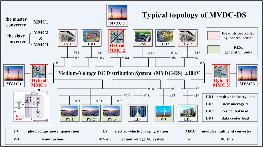
FIGURE 1. Typical topology of MVDC-DS.
It is worth mentioning that, in the proposed MVDC-DS, EV charging stations are equipped with independent energy storage equipment. They can adjust the charging and discharging power of EV and energy storage equipment. By this way, the dispatching instructions can be executed accurately. In this process, the control center does not need to consider whether there is EV charging in the station. Therefore, the uncertainty of EV does not affect the execution of dispatching instructions.
When the MVDC-DS operates in the normal state, the control center makes scheduling plans based on the obtained forecast data, and dispatches instructions to the units controlled by control center. Then, the local controller of units receives and executes the instructions in the specified time.
The stability of DC bus voltage is the key to ensure the security and stability of the DC distribution system. However, the proposed MVDC-DS has complex and diverse characteristics. Therefore, appropriate control strategies of all units including MMCs should be properly selected to ensure the stability of DC bus voltage. Master-slave (M-S) control, as a typical coordinated control strategy (Xie et al., 2021), is adopted in this system. The master converter adopts constant voltage control to stabilize the DC bus voltage. In the MVDC-DS mentioned in Figure 1. MMC1 is set as the master converter. The slave MMC generally adopts constant power control. However, the MMC with this control cannot respond to the fluctuations and uncertainties of RESs and loads quickly. Therefore, it is more suitable to apply droop control to slave MMC in this MVDC-DS. The control modes of other units, such as EV charging stations, ESSs and RESs are set as constant power control.
The control target of constant voltage control or constant power control is single, so it is hard to improve the flexibilities of these two controls. In this section, the droop control adopted to slave MMC will be discussed in detail. Firstly, this section analyzes the characteristics of traditional droop control. Secondly, the improved method is put forward, and different control methods are compared. Finally, an improved droop control is selected.
The droop control can keep voltage and power near the given reference value. The expression of traditional droop control is shown in Eq. 1. The detailed introductions of the traditional droop control principles can be obtained in Ref. (Zhu et al., 2018).
where kdroop is the droop coefficient, P and V are the real values of power and voltage respectively, Pref and Vref are the reference values of power and voltage respectively.
During the operation of MVDC-DS, when the demand of loads or the output of RESs fluctuates slightly, the system can operate stably under the traditional droop control, the deviations of power and voltage are small. When the demand of loads or the output of RESs changes greatly, as shown in the Figure 2, the slave MMC operates at the point Pa, the voltage will be lower than the allowable lower limit of DC voltage, affecting the safety of the MVDC-DS operation.
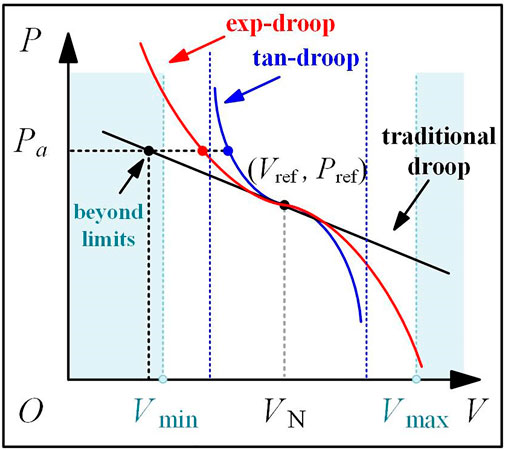
FIGURE 2. Comparison of traditional droop control and improved droop controls.
In order to improve the sensitivity of droop control to voltage deviation when there is a large fluctuation, the slopes of droop function at the positions deviating from reference voltage should be increased. The tan-function and exp-function are used in this paper to improve the traditional droop control. The droop functions modified by the tan-function and exp-function can be expressed as:
The three different droop curves are shown in Figure 2. Under the conditions of small fluctuations, the curves of the two improved controls and the traditional droop control almost coincide, the control effects are similar. When the demand of loads or the output of RESs changes greatly, the DC voltage of slave MMC deviates too much from the reference value. At this time, the MMC adopted these two different improved droop controls will increase the output power and tend to constant voltage control mode. The tan-droop control is more sensitive to voltage deviation than exp-droop control due to its higher slope. However, when the value of
The characteristics of these three different controls are summarized as follow.
1) When the power fluctuation is small, the dynamic responses of the three controls are similar.
2) When the power fluctuation is large, the voltage deviations of tan-droop control and exp-droop control are small.
3) The control curve of tan-droop control diverges at some operating points. The required control effect cannot be achieved.
Therefore, it is more suitable to apply exp-droop control to slave MMC.
Based on the above control strategy of MVDC-DS, this section proposes a dual-time scale energy management based on improved droop control. This method consists of three parts: dual-time scale coordinated energy management framework, reference optimization and coefficient optimization.
Based on the long time forecast data of PV, WT and loads, the reference optimization optimizes the dispatching instructions of each MMC, ESS and EV charging station aiming at minimizing the cost. Based on the short time forecast data, the coefficient optimization optimizes the droop coefficients. In addition, the droop control functions are improved, so that MVDC-DS can respond to the uncertainties and fluctuations of RESs and loads quickly. The input and output of different optimizations and the dual-time scale framework are illustrated in Figure 3.
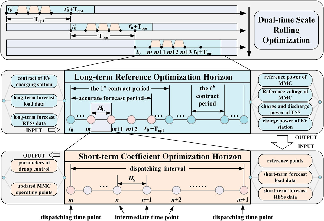
FIGURE 3. Schematic diagram of dual-time scale rolling optimization.
Noted that, in this paper, the reference optimization is triggered at interval (Wang et al., 2019; Jin et al., 2020; Zhu et al., 2021), which is defined as “optimization interval” Topt. The time point when the control center makes and sends dispatching instructions to MMC, ESSs and EV charging stations is defined as “dispatching time point”. The time interval between each two adjacent dispatching time points is defined as “dispatching interval”
In this paper, the total duration of reference optimization is set as the sum of three contract periods of EV charging stations, and the optimization interval is set as 1 h. In order to balance the accuracy and speed of solution, according to the property that “the short time forecast data is more accurate than the long time forecast data” (Li et al., 2019b), the optimization period of long time scale is divided into “accurate forecast period” and “other periods”, and the “accurate forecast period” is set to the 1 h near to the “dispatching time point”.
In this paper, the reference optimization minimizes the total cost of the MVDC-DS in long term operation. The total cost function is shown in Eq. 4.
where
The constraint of power balance is shown in Eq. 5.
where
Considering the operation safety of ESS, the constraints on the state of charge (SOC) are shown in Eqs 6–8.
where
Considering the contract of EV charging stations, the constraints of them is shown in Eq. 9.
where,
In the short time scale, the droop coefficients of each slave MMC are optimized according to the short time forecast data of RESs and loads. The objective function is shown in Eq. 10.
where
Coefficient optimization is subject to the same constraints of the reference optimization. In addition, there are the droop control constraints of MMC at each intermediate time point. The constraint functions under different droop control functions are shown in Eqs 11, 12.
where
The first term of the Taylor expansion of Eq. 12 is the same as Eq. 11. Therefore, the
The distribution system used to test the proposed energy management and control strategy is shown in Figure 1, which is a ring medium-voltage DC distribution system. The voltage level is ±10 kV. The line lengths of branches are shown in Table 1, where the resistivity is 0.075 Ω/km. As is shown in Figure 4, the test distribution system has four kinds of loads with different characteristics. LD1 is a sensitive industry load, which has high requirements on power reliability and power quality. LD2 is a new microgrid with high penetrated RESs. The value of LD2 is the net load considering the local consumption. When its value is negative, it means the RESs generate too much power and the extra power is sent to the MVDC-DS. LD3 is a residential load with high flexibility. LD4 is a data center, whose main tasks are large-scale data processing and web searching. It has similar characteristics with LD1. The curves of the aforementioned multiple types of loads and the PV, WT covering 24 h are shown in Figure 5.

TABLE 1. Line parameters of MVDC-DS.
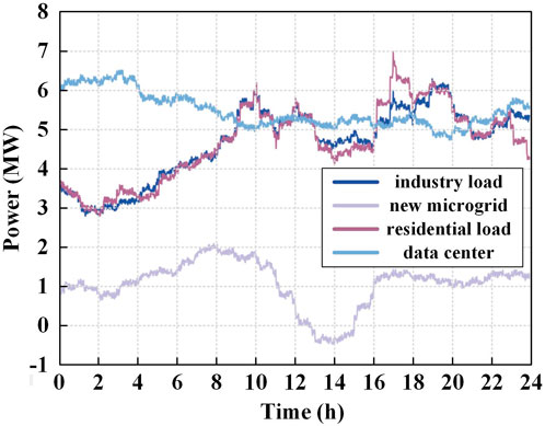
FIGURE 4. Curve of load.
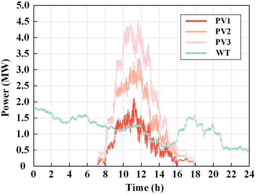
FIGURE 5. Curve of distributed PV and WT.
The characteristics of each MMC, ESS and EV charging station are set in Table 2. The capacity of ESS is

TABLE 2. Parameters of controllable units.
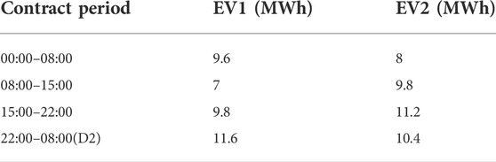
TABLE 3. The contract of EV charging stations.
Based on the system described above, the traditional particle swarm optimization is used to solve the dual-time scale energy management problem of the ±10 kV ring MVDC-DS. Then, the results of energy management optimization are taken as the known parameters in the simulation. In the end, the simulation of MVDC-DS is carried out based on the MATLAB/Simulink platform. The economic benefits and the security performances of the proposed energy management and coordinated control strategy are illustrated in the remaining content.
According to the different control modes of slave MMC and ESS configuration, 4 scenarios are set in this paper, as shown in Table 4.
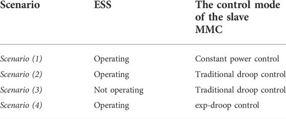
TABLE 4. The four Scenarios.
Scenario (1): The slave MMC adopts constant power control.
Scenario (2): The slave MMC adopts traditional droop control with optimized coefficients.
Scenario (3): ESS is not operating, and the slave MMC adopts traditional droop control with optimized coefficients.
Scenario (4): The slave MMC adopts exp-droop control with optimized coefficients.
This section is used to verify the effectiveness of dual-time scale energy management method. The total cost of purchasing power and the total line loss under the four scenarios are shown in Table 5. It can be seen from this table that there is little difference in system economy between Scenario (1), Scenario (2) and Scenario (4). By comparing the cost in Scenario (1) and Scenario (2), we can find that, the improvement of droop control can help system to further reduce the electricity purchasing cost. The detailed analysis of the system economy will be introduced from the impact of ESS on the MVDC-DS and the contract responses of EV charging stations.
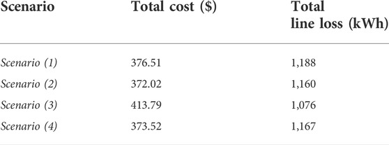
TABLE 5. Total cost and total line loss.
The curves of SOC and price are shown in Figure 6. As can be seen from this figure, the charging periods of ESS are concentrated in 00:00–10:00 and 15:00–18:00 that are the periods with lower prices, the discharging periods of ESS are concentrated in 10:00–15:00 and 18:00–21:00 that are the periods with higher pricse. The ESS can reduce the cost of purchasing power by charging and discharging at different prices. However, this behavior will lead to an increase in power flow, increasing the line loss. That is, the total line loss of Scenario (2) 1,160 MWh is larger than that of Scenario (3) 1,076 MWh.
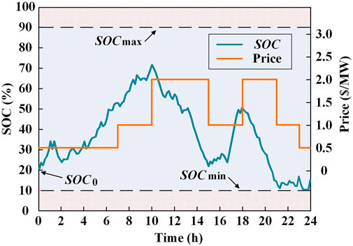
FIGURE 6. SOC of ESS and price curve.
By comparing the total cost of purchasing power in Scenario (2) and Scenario (3) in Table 5, it can be seen that when slave MMC adopts the same control, the total cost of purchasing power without ESS Scenario (3) is 413.79$, and that with ESS Scenario (2) is 372.02$. The total cost is reduced by about 11%. That is, the energy management method proposed in this paper can significantly improve the economy of the system through scheduling of ESS flexibly.
The curves of the charging power of EV1 and EV2 charging stations and the electricity price are shown in the Figure 7. In the first contract period (00:00–08:00), price is higher during 07:00–08:00. According to the proposed energy management method, the control center tends to dispatch instructions to both EV charging stations to charge as early as possible. Therefore, the charging instructions received by both EV charging stations are 0 MW during 07:00–08:00. Similarly, in the other contract period, EV charging stations charge at lower prices to reduce charging costs. It should be noted that, this section is only used to verify the effectiveness of the proposed method. So, the responses of EV charging stations in the fourth contract period (22:00–08:00(D2)) is plotted from 22:00 to 24:00, and the responses for other periods are not plotted.
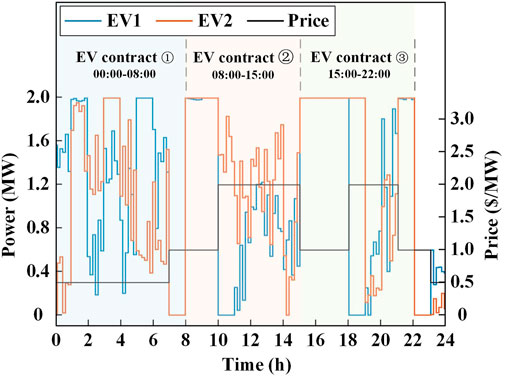
FIGURE 7. Optimal dispatching of EV charging station and price curve.
The economy of the MVDC-DS in steady-state operation has been analyzed. This section focuses on the power quality and dynamic response characteristics of this system.
To evaluate the performances of the proposed energy management method in terms of power quality, two different droop controls are compared in Figure 8. The voltage deviation rate
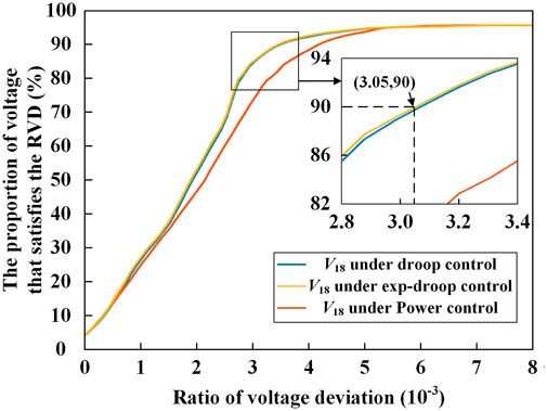
FIGURE 8. Voltage deviations under different control modes.

TABLE 6. Variable and indicator of voltage deviation.
Figure 8 shows the values of
Therefore, compared with constant power control, these different droop controls can help system reduce the voltage deviation in steady-state operation, and improve power quality under small fluctuations of RESs or loads. The exp-droop control has better control effect.
At each dispatching interval, the coefficients of droop control will be optimized, and at each intermediated time point within the interval, the coefficients will not change. However, the power of RESs and loads fluctuate slightly at any time.
It is assumed that the power of RESs and loads fluctuates randomly at 14:08:60. In this paper, the voltage of node 18 is selected to analyze the control effect. At this moment, the maximum of voltage fluctuation is 0.5% Vref under two different droop controls as shown in Figure 9. The voltage fluctuations are very small. This figure shows that there are almost no differences in the control effect under these controls when the power fluctuation is small.

FIGURE 9. The V18 under small fluctuation.
Based on the aforementioned dual-time rolling optimization, the slave MMC, ESS, EV charging station, PV and WT will execute the dispatching instructions at each dispatching time point, and their reference points will be updated. This is the moment when the MVDC-DS operating status changes, so the power will fluctuate.
In this paper, the voltage of node 18 at 14:10:60 is selected to analyze the control effect. At this moment when the dispatching instruction is executed, the voltage will jump as shown in Figure 10. Subsequently, the voltage rapidly stabilizes under these different droop control methods. This condition also belongs to the situation of slight power fluctuation, and the effects of these droop controls are relatively similar.
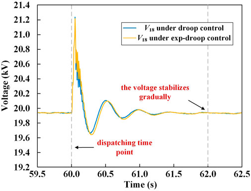
FIGURE 10. The V18 at dispatching time point.
When the short time forecast data of RESs or loads deviates greatly from the real data, the DC voltage of MVDC-DS will deviate greatly. It is assumed that the load of data center at node 18 surges by 120% from 5.18 to 11.4 MW at 14:15:03 due to the demand of short time big-scale data processing.
In the MATLAB/Simulink, the DC voltage under two different droop controls are shown in Figure 11. When the slave MMC adopts the traditional droop control, the V18 will drop sharply, which is lower than the lower limit of the voltage range, that is,

FIGURE 11. The V18 under load surging.
Therefore, compared with the traditional droop control, the proposed exp-droop control can cope with the large fluctuations of RESs and loads, and improve the operation safety of MVDC-DS under extreme conditions.
This section summarizes and analyzes the characteristics of four different scenarios in terms of economic benefits, power quality and dynamic response. The comparison of different scenarios is shown in Table 7. Since ESS is not involved in the optimization, the system in Scenario (3) has the worst economic benefits. Due to the constant power control, the system in Scenario (1) has the worst power quality and dynamic response. In Scenario (4), the ESS participates in the optimized operation, and the improved droop control is used, so its results are the best in all aspects.
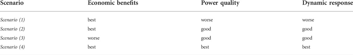
TABLE 7. Comparison of different scenarios.
Considering the economy and power quality problems caused by the fluctuations of the RESs and loads, this paper proposes a dual-time scale energy management method based on exp-droop control for medium-voltage DC distribution system. A series of simulations show that:
1) A ±10 kV three-terminal MMC ring MVDC-DS is constructed in this paper, and all MMCs adopt the hybrid topology that can realize fault ride-through operation. This system can schedule controllable units to provide reliable energy for multiple types of loads under various operating conditions.
2) The dual-time scale energy management method can realize the co-optimization of system-layer instructions and converter-layer coefficients. By co-optimizing the operating power and droop coefficients for hybrid MMC in dual-time scale, the electricity purchasing cost can be reduced by up to 11%.
3) The exp-droop control proposed in this paper can help system to reduce voltage deviation in steady-state operation. The number of all “intermediate time points” satisfying the voltage deviation rate below 0.305% accounts for more than 90%.
4) All DC bus voltages of MVDC-DS based on the exp-droop control are always above the lower limit of 93% UN in different conditions, such as small power fluctuation, dispatching instruction execution and load surging by 120%.
The economy and power quality of MVDC-DS are improved under the energy management method and improved droop control proposed in this paper. However, how to achieve the optimal control parameters and how to further improve the dynamic response of this system are the challenges for future study.
The original contributions presented in the study are included in the article/supplementary material, further inquiries can be directed to the corresponding author.
WL and QX propose the dual-time scale energy management method based on improved droop control for the medium-voltage DC distribution system (MVDC-DS). HJ, YM, MC, YJ, and TL collect the data for MVDC-DS. WL, QX, YZ, and XY analyzes the cases for MVDC-DS.
This work was supported by the National Natural Science Foundation of China (No. 52107121), Seed Foundation of Tianjin University (No. 220675) and the joint project of NSFC of China and EPSRC of UK (No. 52061635103 and EP/T021969/1).
The authors declare that the research was conducted in the absence of any commercial or financial relationships that could be construed as a potential conflict of interest.
All claims expressed in this article are solely those of the authors and do not necessarily represent those of their affiliated organizations, or those of the publisher, the editors and the reviewers. Any product that may be evaluated in this article, or claim that may be made by its manufacturer, is not guaranteed or endorsed by the publisher.
Chen, Q., Wang, K., Li, G., Han, B., Xu, S., and Wei, Z. (2017). Hierarchical and distributed optimal scheduling of AC/DC hybrid active distribution network. Proc. CSEE 37, 1909–1917.
Fu, Y., Zhang, Z., Li, Z., and Mi, Y. (2020). A two-stage robust game approach for coordinated energy management in hybrid AC/DC distribution system with microgrid clusters. Proc. CSEE 40, 1226–1240.
Hou, H., Wang, Y., Zhao, B., Zhang, L., Chen, Y., and Xie, C. (2022). Electric vehicle aggregator dispatching strategy under price and incentive demand response. Power Syst. Technol. 46, 1259–1268.
Ji, Y., Yuan, Z., Zhao, J., Li, Y., and Xu, S. (2016). A suitable voltage control strategy for DC distribution power network. Proc. CSEE 36, 335–341.
Jia, H., Qian, X., and He, J. (2019). An improved grid current and DC capacitor voltage balancing method for three-terminal hybrid AC/DC microgrid. IEEE Trans. Smart Grid 10, 5876–5888. doi:10.1109/tsg.2018.2834340
Jin, G., Pan, D., Chen, Q., Shi, C., and Li, G. (2021). Energy optimization method of multi-voltage-level DC distribution network considering adaptive real-time scheduling. Power Syst. Technol. 45, 3906–3916.
Jin, L., Fang, X., Cai, Z., Chen, D., and Li, Y. (2020). Multiple time-scales source-storage-load coordination scheduling strategy of grid connected to energy storage power station considering characteristic distribution. Power Syst. Technol. 44, 3641–3648.
Li, K., Gao, Z., Wu, Y., and Zhengguang, L. (2019). Remaining lifetime prediction of AC contactor based on statistical regression and nonlinear wiener process. Trans. China Electrotech. Soc. 34, 4058–4070. doi:10.19595/j.cnki.1000-6753.tces.180764
Li, X., Guo, L., Huang, D., Zhao, Y., and Wang, C. (2019). Research review on operation and control of DC distribution networks. High. Volt. Eng. 45, 3039–3049.
Lin, L., Ma, M., Jin, X., Wang, S., Zhu, L., and Fan, M. (2021). DC-bus voltage robust control of VSC considering the instantaneous power of AC- and DC-side in DC distribution network. Proc. CSEE 41, 5827–5841.
Ma, J., Geng, G., and Jiang, Q. (2016). Two-time-scale coordinated energy management for medium-voltage DC systems. IEEE Trans. Power Syst. 31, 3971–3983. doi:10.1109/tpwrs.2015.2504517
Meng, X., Li, K., Wang, Z., and Huo, X. (2015). A hybrid MMC topology and its DC fault ride-through capability analysis when applied to MTDC system. Automation Electr. Power Syst. 39, 72–79. doi:10.7500/AEPS20150307001
Peng, K., Xian, R., Zhang, X., Chen, Y., and Lu, H. (2016). Hierarchical power flow control strategy and algorithm for multi-terminal interconnected AC/DC distribution network. Automation Electr. Power Syst. 40, 72–77.
Qian, X., Chen, L., Jin, Y., Mu, Y., Cupertino, A. F., Jia, H., et al. (2021). An improved fault-tolerant control scheme for cascaded H-bridge STATCOM with higher attainable balanced line-to-line voltages. IEEE Trans. Ind. Electron. 68, 2784–2797. doi:10.1109/tie.2020.2978716
Qian, X., Lu, W., Jin, Y., Mu, Y., Yu, X., and Jia, H. (2021). “An improved master-slave control strategy for medium voltage DC distribution system,” in The 5th IEEE Conference on Energy Internet and Energy System Integration, Taiyuan, China, 22-24 October 2021.
Sun, F., Ma, J., Yu, M., and Wei, W. (2019). A robust optimal coordinated droop control method for multiple VSCs in AC-DC distribution network. IEEE Trans. Power Syst. 34, 5002–5011. doi:10.1109/tpwrs.2019.2919904
Wang, C., LL, C., Li, P., Li, S., and Zhao, K. (2019). Multiple time-scale optimal scheduling of community integrated energy system multiple time-scale optimal scheduling of community integrated energy System. Proc. CSEE 39, 6791–6803.
Wang, C., Peng, L., and Yu, H. (2018). Development and characteristic analysis of flexibility in smart distribution network. Automation Electr. Power Syst. 42, 13–21.
Wang, C., Wang, R., Yu, H., Song, Y., Yu, L., and Li, P. (2020). Challenges on coordinated planning of smart distribution networks driven by source-network-load evolution. Proc. CSEE 40, 2385–2395.
Xie, X., Quan, X., Wu, Z., Cao, X., Dou, X., and Hu, Q. (2021). Adaptive master-slave control strategy for medium voltage DC distribution systems based on a novel nonlinear droop controller. IEEE Trans. Smart Grid 12, 4765–4777. doi:10.1109/tsg.2021.3104413
Xiong, X., Ji, Y., Li, R., Sun, L., Wu, M., and Liu, H. (2018). An overview of key technology and demonstration application of DC distribution and consumption system. Proc. CSEE 38, 6802–6813.
Zhao, M., Jiao, Z., and Rui, L. (2017). Network structures and key technologies of DC distribution systems. Power Syst. Technol. 41, 3348–3357.
Zhao, X., Peng, K., Zhang, X., Xu, B., Chen, Y., and Zhao, Y. (2019). Analysis on dynamic performance of droop control for multi-terminal VSC based DC distribution system. Automation Electr. Power Syst. 43, 89–96.
Zhou, F., and Huang, W. (2014). Study on the key technology of DC distribution power network. Power Syst. Prot. Control 42, 62–67.
Zhu, L., Tian, Z., Tang, L., Li, X., and Cui, K. (2021). Multi-time-scale optimal dispatch of regional integrated energy system considering level of detail direct load control. Power Syst. Technol. 45, 2763–2772.
Keywords: medium-voltage DC distribution system, improved droop control, dual-time scale optimization, energy management, parameter optimization
Citation: Lu W, Xiao Q, Jia H, Mu Y, Cui M, Jin Y, Li T, Zhang Y and Yu X (2022) An improved energy management for MVDC distribution system based on exponential droop control. Front. Energy Res. 10:995968. doi: 10.3389/fenrg.2022.995968
Received: 16 July 2022; Accepted: 10 August 2022;
Published: 01 September 2022.
Edited by:
Yonggang Peng, Zhejiang University, ChinaReviewed by:
Xiangyu Wu, Beijing Jiaotong University, ChinaCopyright © 2022 Lu, Xiao, Jia, Mu, Cui, Jin, Li, Zhang and Yu. This is an open-access article distributed under the terms of the Creative Commons Attribution License (CC BY). The use, distribution or reproduction in other forums is permitted, provided the original author(s) and the copyright owner(s) are credited and that the original publication in this journal is cited, in accordance with accepted academic practice. No use, distribution or reproduction is permitted which does not comply with these terms.
*Correspondence: Qian Xiao, eGlhb3FpYW5AdGp1LmVkdS5jbg==
Disclaimer: All claims expressed in this article are solely those of the authors and do not necessarily represent those of their affiliated organizations, or those of the publisher, the editors and the reviewers. Any product that may be evaluated in this article or claim that may be made by its manufacturer is not guaranteed or endorsed by the publisher.
Research integrity at Frontiers
Learn more about the work of our research integrity team to safeguard the quality of each article we publish.