 Zhiqi Kong1†
 Wei Du
- 1Beijing Power Machinery Institution, Beijing, China
- 2School of Energy Science and Engineering, Harbin Institute of Technology, Harbin, China
This study focuses on the effects of three groove tip structures (full rib groove tip, partial rib tip on the suction side, and partial rib tip on the pressure side) on tip leakage flow, aerodynamic characteristics of a cascade, and heat transfer in a gas turbine blade. The groove’s width B = 1.6 mm, while the tip clearance is τ = 1.2 mm. Results of the flow parameters, fluid flow, and heat transfer in the recessed channel are discussed. The results show that all ribbed tips obtain more uniform outlet flow angle distribution and higher aerodynamic performance than the plane tips. The total aerodynamic pressure loss of the ribbed tips on the pressure side is the same as that of complete ribbed tips. The evolution mechanisms are different, although both can improve the turbine efficiency. Although the partial rib tip on the pressure side weakens the mixing of the channel vortex and leakage vortex near the trailing edge and has the best control effect on the leakage vortex, the lack of the suction side rib will make it easier for the low-energy fluid to flow into the gap from the front of the suction side, which is not conducive to reducing the leakage flow inside the gap; the full rib tip not only minimizes the tip relative leakage flow and leakage loss but also increases the channel vortex loss. With the complex vortex system in the groove and the rib blocking effect at the leakage outlet, the suction-side rib tip becomes the tip structure with the best leakage flow control effect under the same clearance, but the leakage vortex loss is the highest.
Introduction
The gas turbine has the advantages of compact structure, large thrust weight ratio, rapid start-up regulation, and low carbon emission, and it is widely used in aviation propulsion, gas power generation, ship power, distributed energy supply, and other fields.
As a rotating part, as shown in Figure 1, in order to avoid friction between the rotating blade and the casing, a clearance of 1%–2% blade height is generally retained between them, which is called tip clearance. The tip gap between the high-speed spinning rotor and the stationary casing inevitably results in the leakage of high-temperature gas. The blade tip clearance of the turbine is bound to make the blade tip completely exposed to high-temperature gas, resulting in blade tip oxidation and ablation, increasing the turbine energy loss and shortening the service life of the blade. Bunker R S (Bunker, 2001; Bunker, 2006) research shows that the larger the clearance, the greater is the stage efficiency and performance loss. Compared with large engines, the smaller the blade height of small engines, the greater is the proportion of moving blade tip clearance in radial blade height, and the more sensitive are the efficiency and temperature to the change of clearance.
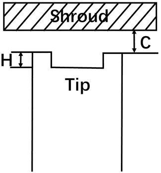
FIGURE 1. Rotor blade groove tip clearance.
Researchers at home and abroad have carried out a lot of research work on the aerodynamic and heat transfer characteristics of high-pressure turbine blade tips. Predecessors have studied the flow and heat transfer mechanism of the aforementioned different types of tip structures. Heyse et al. (Nyland et al., 1971) compared two kinds of shoulder wall tips: the shoulder wall tip with a single pressure surface rib and the shoulder wall tip with a single suction surface rib. The shoulder wall tip with the rib on the suction surface has an obvious effect of reducing leakage loss than the plane tip. Nho et al. (2012) studied the leakage flow of the double-cogged tip structure and plane tip structure, and the results showed that the losses of the double-cogged tip structure were smaller than those of the plane tip structure. Wang et al. (2015) carried out two-dimensional cascade experiments to study the internal flow field of the shrouded tip. The deflection angle of the leakage flow is very small, while the deflection of the mainstream is large after the outflow. It is verified that there is a mixing loss between the leakage fluid of the shrouded structure and the high-temperature mainstream.
The geometry of the rib will shift the flow vortex system in the groove in the tip area and affect the aerodynamic situation of the cascade. Both active and passive measures, including modifications to gap height or tip geometry type, and tip air cooling (Metzger et al., 1989; Teng et al., 2001; Azad et al., 2002; Ahn et al., 2005; Bunker, 2005; Key and Arts, 2006), have been considered and investigated by researchers to account for the tough aerothermal conditions on the blade tips. Lee and Choi (Lee and Choi, 2010a; Lee and Choi, 2010b) studied the influence of clearance on the aerodynamic losses between flat and squealer tip blades. The results revealed that the cavity squealer tip was beneficial to reduce the leakage flow from the leading edge to the mid-chord region of the blade compared to the plane tip blade. In addition, the tip leakage loss increased with increasing clearance, but the passage vortex loss did not change significantly in a cavity squealer tip blade. Metzger (Wheeler et al., 2011) researched the heat transfer characteristics of blade tip clearance of static grooves under different Reynolds numbers and aspect ratios through an experimental method. The deeper the groove, the smaller is the heat transfer coefficient. Park et al. (2015) analyzed the influence of the number of grooves on the heat transfer and flow of the blade tip structure. The research shows that increasing the number of grooves is beneficial to weakening the total pressure loss coefficient, and adding transverse ribs is beneficial to reducing the heat transfer coefficient of the leading edge. Tallman (2004) studied the rib tip before and after improvement by numerical simulation. The results indicate that pressure edge rounding will increase the leakage flow, while suction edge rounding will undermine the leakage vortex. The improved method of the grooved blade tip proposed by Mischo et al. (2011) can greatly lower the reflux intensity in front of the groove and improve the loss in the gap and the heat transfer characteristics of the blade tip.
In the process of studying the corresponding leakage flow mechanism of the tip structure and vortex evolution, predecessors are also exploring the factors that have a great impact on blade performance. Heyes et al. (1992) experimentally investigated the tip leakage performance of a linear cascade with various tip geometries, including plain tips and pressure-side (PS) and suction-side (SS) squealer tips. The results showed that the squealer tip, especially the suction-side form, helped control the leakage flow and leakage loss. Key and Arts (2006), respectively, studied the leakage flow of the plane tip structure and grooved tip structure at high speed. The results show that slight backflow occurs in the groove. The grooved blade tip has a stronger weakening effect on the tip leakage vortex than the plane blade tip and causes the secondary flow of the channel to deflect to the blade tip, which can further reduce the total pressure loss at the outlet. Lee et al. (2009) measured the internal flow field and total pressure loss of different rib heights at the groove tip under different clearance dimensions and the same tip clearance. In the case of the same gap size, the higher the rib height, the smaller the total loss, the closer the rib height, and the higher the efficiency. Bunker et al. (Azad et al., 2000) studied the change of heat transfer at the rib tip after changing the rib height under the plane cascade. In 2000, Azad et al. (Newton et al., 2006) conducted experiments on the surface heat transfer characteristics of the GE-E3 grooved blade tip. Newton (Kang and Lee, 2016) and Krishnababu et al. (Virdi et al., 2015) compared the heat transfer and flow characteristics of the plane blade tip, partial rib blade tip on the single suction side, and full rib blade tip. The leakage flow of the grooved blade tip is lower than that of the plane blade tip, the strength of the leakage vortex is weaker, the heat transfer coefficient is lower, and the rib on the suction side will enhance the leakage flow.
Computational models
The physical model and mesh detail are presented in Figure 2. The blade prototype is LISA 1.5 with high power and a low aspect ratio first stage rotor blade of the turbine. Considering blade distortion, a three-dimensional blade is formed. The LISA 1.5 axial turbine in the turbomachinery Laboratory of the Federal University of Technology in Zurich was obtained by Dr. Behr (Yamamoto et al., 1995) after improving the original Lisa stage 2 turbine. His study records the complete blade geometry and experimental data in detail. The specific geometric parameters at different sections are shown in Table 1. The structural diagram of the three grooved blade tops used in this study is displayed in Figure 3.
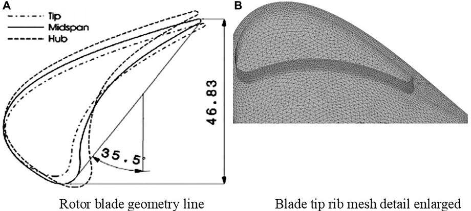
FIGURE 2. Physical model and mesh detail. (A) Rotor blade geometry line. (B) Blade tip rib mesh detail enlarged.
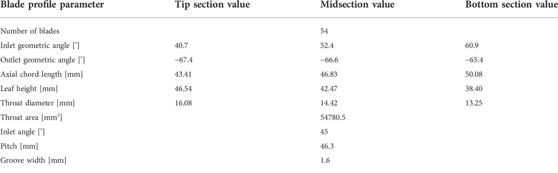
TABLE 1. Geometric parameters of different sections of the model.
FIGURE 3. Structural diagram of the blade top without the cold air groove. (A) Full rib groove tip structure. (B) Pressure-side partial rib groove blade tip structure. (C) Suction-side partial rib groove blade tip structure.
Numerical analysis
Boundary conditions
The boundary conditions for simulation calculation are given in Table 2, and the turbulence model selected the SST k-ω, which added γ-θ transition. We used ideal gas in the calculation. The length of the inlet segment is 1.5 times the string length, and the length of the outlet segment is 2.5 times the string length. In the Boundary conditions part, we have shown the relevant boundary condition. Except for the inlet and outlet, the surface of the blade, hub, and casing are assigned the properties of insulation, no-slip, and smooth wall, respectively. The “Stage” treatment is adopted for the turn-to-static interface.
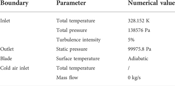
TABLE 2. LISA 1.5 calculation boundary conditions of the turbine blade.
Mesh generation
Wall-resolved RANS grids with y+<1.2 were applied to the blade wall and casing surfaces (Wang et al., 2018). The grid thickness on the solid wall of the blade of the first layer is 1.0
Numerical calculation and validation
In this study, the efforts to verify the accuracy of the CFX simulations are conducted. The RMS residuals of the monitored equations (continuity, momentum, and energy) reach the −4th, −5th, and −7th powers of 10, respectively. The geometry used for aerodynamic numerical verification is LISA 1.5. The straight blades formed by stretching the blade tip profile of the high-pressure turbine form three rows of a fan-shaped cascade, and the clearance height is set to 0.68 mm. The total pressure coefficient distributed along the spines at the outlet section of each blade row is compared with the experiment of Behr in 1995. It is found that the calculation results of the three turbulence models used in the simulation are in line with the experimental trend. However, as shown in Figure 4, the k-ε and k-ω models underpredicted the results, the distribution trend, and range of the k-ω SST model with γ-θ transition are in good agreement.
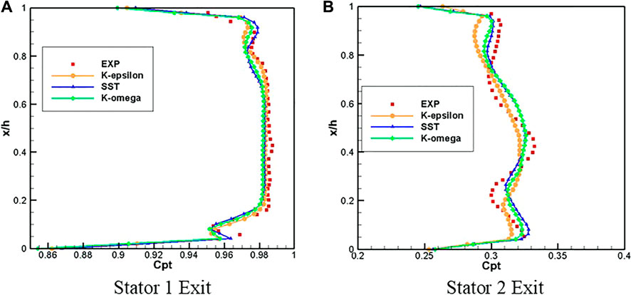
FIGURE 4. Comparison of numerical results with experimental data on the total pressure loss coefficient at the outlet (Behr T.,1995). (A) Stator 1 Exit. (B) Stator 2 Exit.
The model used for heat transfer numerical verification is a linear turbine cascade with film cooling. The straight blade was obtained by stretching the blade tip profile of the first stage rotor blade of the GE-E3 turbine and scaling up. The geometric parameters of the calculation model are shown in table 3. The gap height is fixed to τ/H = 1%, and the length of inlet and outlet sections are 1.5 times and 2.5 times the chord length, respectively. It includes 13 cooling holes, the diameter D of which is 1.29 mm. Figure 5 shows the proven tip for verification of heat transfer characteristics, Figure 5B, a schematic diagram of the blade tip hole, and the distance between the middle arc film holes is shown in 5D. Ignoring the influence of compressibility on heat transfer performance, the heat transfer coefficient h and cooling efficiency at the top of the blade tip rib and the bottom of the groove are calculated and are compared with the plane tip test measured by Kwak under subsonic conditions. In Figure 6, all turbulence models overestimate the h value on the tip surface, especially at the top of the groove rib and near the trailing edge, the predicted results of the k-ε model have the biggest gap with the experimental results, and the range of z1 with high leading edge h is the largest; the high position z3 of the SST turbulence model h is close to the middle of the blade, and the range is the smallest, which is closest to the experimental value. Thus, the k-ωSST model is considered decently acceptable.

TABLE 3. Geometric parameters of the blade tip of the cooling film hole groove.
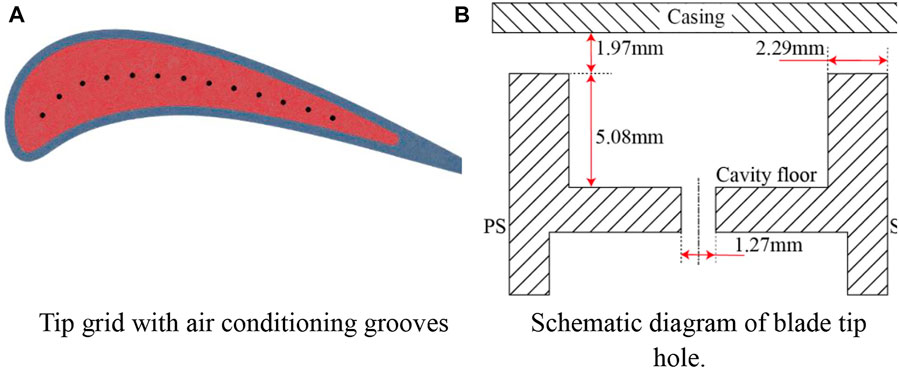
FIGURE 5. Grooved tip for verification of heat transfer characteristics (Nyland T W, Englund D R, Anderson R C,1971). (A) Tip grid with air conditioning grooves. (B) Schematic diagram of the blade tip hole.
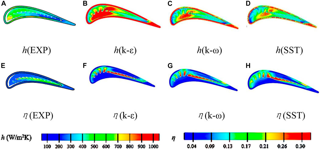
FIGURE 6. Thermodynamic verification: (A–D) h and (E–H) η comparison of the tip.
Solution method
Steady-state incompressible inviscid fluid flow is controlled by the following equation (Liu et al., 2021):
Continuity equation
Momentum equation
The energy equation for fluid is as follows:
The numerical simulation for the fluid flow and heat transfer for the tip leakage flow were conducted with the commercial solver ANSYS-CFX (2019 R2). All predicted quantities were at a steady state. The minimum convergence criterion for the continuity equation is 1e–6.
Data reduction
The total pressure loss coefficient is defined as follows:
where
The static pressure coefficient is defined as follows:
where
The energy loss coefficient of the cascade with cooling air is defined as follows:
where
where
The heat transfer coefficient h is defined (Du et al., 2021a) as follows:
where q is the heat flux.
The adiabatic film cooling efficiency (Du et al., 2021b) is defined as follows:
where
Results and discussion
Aerodynamic performance analysis
Figure 7 shows the flow line and end wall static pressure distribution in the middle section of blade tip clearance. The end wall static pressure program shows that the pressure gradient on the pressure side of the plane tip is larger than that of the ribbed tip, indicating that the speed of leakage flow entering the plane tip clearance is large. Because of the blocking effect of ribs, the ribbed tip forms a low-pressure area on the suction side of greater than 75% axial position. In the ribbed tip structure, the low-pressure area of the pressure-side rib tip is relatively large and distributed at the trailing edge, indicating that the tail pressure gradient and leakage flow turning angle are the largest. The pressure distribution at the full rib tip is relatively uniform. As shown in Figure 7, the flow line in the middle section of the gap shows that the blade tip flow is divided into three flow zones, the leakage flow zone, channel flow zone, and buffer zone, with three flow boundaries: attachment line RL, leakage flow off-line LSL, and channel flow off-line PSL. As shown in Figures 7B, the full rib and in Figures 7C the single pressure-side rib tip, the low-speed fluid in the cascade channel area rushes into the gap and mixes with the leakage flow, resulting in the separation of the leading edge of the blade tip. The LSL is close to the suction side, which shows that the two tips can improve the leakage flow, and the control effect on the pressure rib tip is better. The LSL position of the suction rib tip is the most forward and farthest from the suction side, indicating that the air mixing is the strongest, and the range of leakage vortex is the largest.
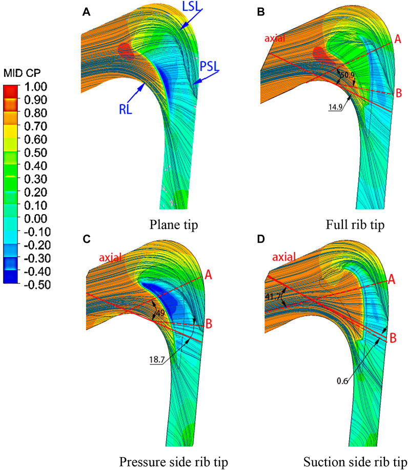
FIGURE 7. Flow line and end wall static pressure distribution in the middle section of blade tip clearance. (A) Plane tip. (B) Full rib tip. (C) Pressure-side rib tip. (D) Suction-side rib tip.
Consequently, based on the aforementioned analysis, the following conclusions can be drawn.
(1) Compared with the flat blade tip, the full rib tip and pressure-side rib tip have a better ability to weaken the leakage vortex;
(2) The pressure-side rib tip has the best control effect on the leakage vortex;
(3) The suction-side rib tip is not conducive to the control of the leakage vortex.
As shown in Figure 7, in order to deeply analyze the tip leakage flow, sections “A” and “B” parallel to the direction of the tip leakage flow streamline.
The total pressure loss distribution diagram can reflect the flow state of leakage flow in the blade tip complete clearance space and straight cascade channel. Figure 8 is the total pressure loss distribution cloud diagram of section “A” and section “B”.
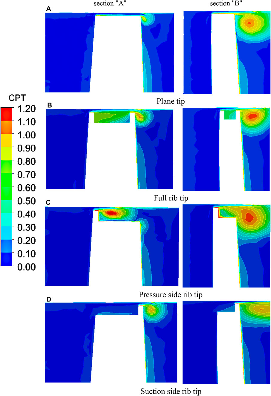
FIGURE 8. Total pressure loss distribution cloud diagram of section “A" and section “B". (A) Plane tip. (B) Full rib tip., (C) Pressure-side rib tip. (D) Suction-side rib tip.
The rib structure will make the leakage vortex size broader and the leakage vortex core lower. As shown in Figure 8B, part of the leakage flow forms a vortex system in the groove, the mixing intensity between the leakage flow and the main flow decreases, and the size of the leakage vortex decreases. As shown in Figure 8C, when the airflow strikes the end wall, it is hindered by the rib on the pressure side to slow down, and a small separation bubble is formed above the rib. The leakage vortex is attached to the rib surface again, the blade tip intrusion flow makes the leakage flow unable to reach the suction side, and the gap leakage flow flows out directly from the suction side without ribs. As shown in Figure 8D, the lack of ribs on the pressure side makes the airflow enter the groove at a high speed, and the ribs on the suction side reduce the leakage flow speed, resulting in a large leakage vortex loss at the gap outlet.
Figure 8 is the total pressure loss distribution cloud diagram of the section “B”. The size and loss of the leakage vortex are higher than those in section “A”, indicating that the leakage vortex is gradually developed along the flow direction. The position of the vortex core at the ribbed blade tip rises upward, and the leakage vortex is attached to the suction-side surface.
Consequently, based on the aforementioned analysis, the following conclusions can be drawn.
(4) Under the same tip clearance dimensions, the ribbed blade tip effectively reduces the leakage loss;
(5) The pressure-side rib tip has a better control effect on the gap leakage flow.
Figure 9 shows the total pressure distribution cloud diagram at the outlet of the cascade. Generally, the higher the total pressure at the outlet, the lower the loss is. Under the same clearance, the high-pressure area of the full rib tip and pressure-side rib tip is larger, indicating that their loss is lower than that of the suction-side rib tip.
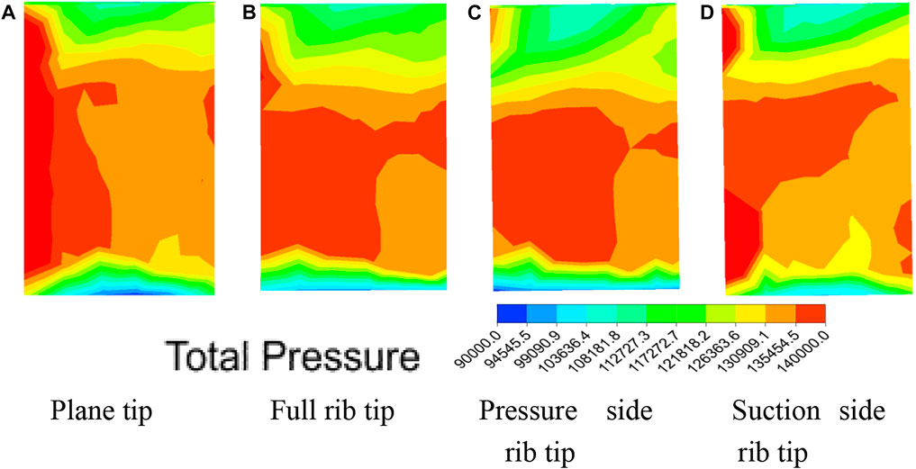
FIGURE 9. Total pressure distribution cloud diagram at the outlet. (A) Plane tip. (B) Full rib tip. (C) Pressure-side rib tip. (D) Suction-side rib tip.
Flow field analysis
Figure 10 shows the streamlined distribution of section “A” and section “B”, which intuitively shows the leakage flow in the cascade and the evolution of the internal vortex system.
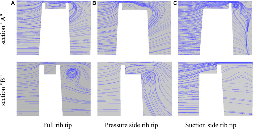
FIGURE 10. Streamline distribution of sections “A" and “B". (A) Full rib tip. (B) Pressure-side rib tip. (C) Suction-side rib tip.
As shown in Figures 10A, there is a slight backflow in the groove, resulting in the upward lifting of the fluid at the outlet of the gap. The leakage flow forms a leakage vortex outside the rib on the suction side. Along the flow direction, the intensity of the vortex in the groove from a to B weakens, and most of the leakage flow directly passes through the gap on the suction side. As shown in Figures 10B, the stagnation effect of pressure-side ribs reduces the fluid flow rate entering the blade tip clearance. Part of the leakage flow enters the groove cavity in the form of a wall jet to form a relatively developed vortex system. The mixing process of the tip intrusion flow and pressure-side leakage flow at A is intensive, resulting in the leakage flow being unable to reach the suction side. The situation at tail edge B is similar to that of the full rib blade tip, the flow perpendicular to the bottom of the groove appears on the suction side, the strength of the leakage vortex outside the suction side is weakened, and the vortex core position is the lowest. As shown in Figure 10C, the loss of ribs on the pressure side leads to large flow velocity, but the vortex system in the groove is underdeveloped, and a miniature vortex is formed at the junction of the suction-side rib and the bottom of the groove. The strength of the leakage vortex outside the suction side is much stronger than that of the other two blade tips because part of the fluid impacts the suction-side rib, and the vortex core position is closer to the suction-side wall.
Aerodynamic loss evaluation
As aerodynamic losses affect aero-engine performance and efficiency, this section discusses the influence of groove tip structures and leakage flow rates on these losses. The total pressure loss coefficient is defined as follows:
where
According to the aforementioned analysis, under the same tip clearance, the non-cooled ribbed tip structure will not only affect the leakage flow but also cause changes in the leakage vortex and channel vortex. Table 4 shows the effects of different tip structures on aerodynamic parameters such as total loss and relative leakage flow of the cascade.
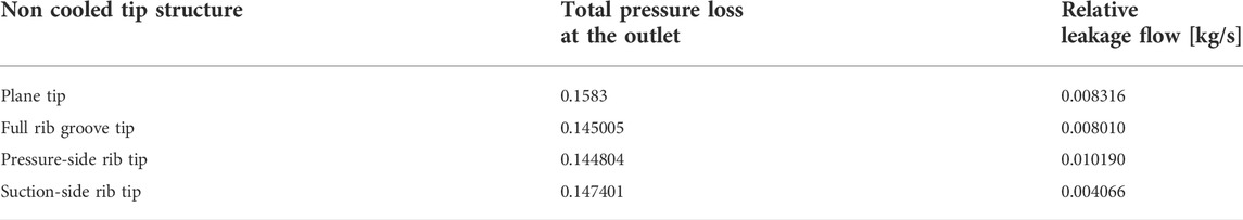
TABLE 4. Outlet aerodynamic parameters of different non-cooled tip structures.
It can be seen from the aforementioned table that under the same clearance conditions, the loss of the structure after adding ribs to the blade tip is smaller than that of the plane blade tip, and the total pressure loss at the outlet of the rib tip on the pressure side is the smallest, about 0.144804. The total aerodynamic pressure loss of the rib tip on the pressure side is basically the same as that of the full rib tip, which is considerably lower than that of the rib on the suction side, and the maximum tip loss is 0.147401.
In terms of relative leakage flow, adding ribs to the plane blade tip will form an air seal on the gap, but the rib blade tip on the pressure side is not conducive to reducing the leakage flow. The leakage flow in the gap is the highest, about 18.4% more than that of the plane blade tip; although the full rib groove tip has a control effect on the leakage flow, it is not as obvious as the rib tip on the suction side. As described earlier, the rib tip on the suction side becomes the tip structure with the best control effect on the leakage flow under the same clearance by virtue of the complex vortex system in the groove and the rib blocking effect at the leakage outlet, and the relative leakage flow is about 0.004066 kg/s, about 51.1% less leakage than the flat blade tip.
Figure 11 shows the distribution of the total pressure loss coefficient along the blade height after the pitch averaging algorithm at the outlet of the aforementioned four-ribbed blade tip structures. As shown in Figure 10, the high loss area of 0.94–0.98H is dominated by the leakage vortex, and the high loss area of 0.82–0.90H is dominated by the channel vortex; the three kinds of ribbed groove tips reduce the loss around 0.95H blade height and increase the loss near 0.84H blade height, which shows that the addition of ribs at the plane tip can inhibit the tip leakage vortex but promote the development of the channel vortex. Among the three kinds of ribbed tips, the loss value of the whole rib tip is the largest at the blade height of 0.84H, and the loss of the rib groove tip on the pressure side is the smallest near the blade height of 0.95H, which indicates that the rib groove tip on the pressure side has the strongest weakening effect on the tip leakage vortex and also has a certain weakening effect on the channel vortex.
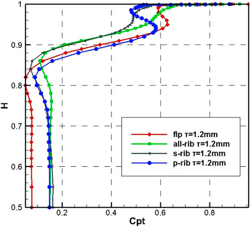
FIGURE 11. Average total pressure loss coefficient of pitch is distributed along the blade height.
To sum up, under the same clearance condition, the loss of all ribbed groove tips is smaller than that of plane tips, the total pressure loss at the outlet of rib tips on the pressure side is the smallest, but the leakage flow in the clearance is the highest, and the tip loss of ribs on the suction side is the highest, which has the best effect on leakage flow control.
Conclusion
This study compares the plane tip, full rib groove tip, pressure-side rib tip, and suction-side rib tip under the condition of no cold air injection in the same tip clearance, explores the development and evolution process of secondary flow in the tip area, and analyzes the influence of the tip structure on leakage flow and cascade aerodynamic characteristics. The main conclusions are summarized as follows:
(1) Under the same clearance size, all ribbed tips can obtain stronger aerodynamic performance than plane trips. The full rib tip is beneficial to control the relative leakage flow and leakage vortex loss, but the increase in channel vortex loss makes the total pressure loss slightly higher than the pressure-side rib tip.
(2) The pressure-side rib tip has the best control effect on the leakage vortex and the lowest aerodynamic total pressure loss, but it is not conducive to reducing the clearance leakage flow. The suction-side rib tip has the least leakage flow, but the largest leakage vortex loss.
(3) For the internal flow field of the ribbed blade tip, the vortex intensity in the groove decreases along the flow direction, and the vortex intensity of the leakage vortex increases along the flow direction. There is backflow in the groove of the full rib tip, and most of the leakage flow forms a leakage vortex (TLV) directly at the outlet of the suction side.
Data availability statement
The original contributions presented in the study are included in the article/Supplementary Material; further inquiries can be directed to the corresponding author.
Author contributions
ZK, TZ, and WD contributed to the conception and calculation of the study. ZK organized the database. TZ performed the statistical analysis. ZK wrote the first draft of the manuscript. All authors contributed to manuscript revision, read, and approved the submitted version.
Conflict of interest
The authors declare that the research was conducted in the absence of any commercial or financial relationships that could be construed as a potential conflict of interest.
Publisher’s note
All claims expressed in this article are solely those of the authors and do not necessarily represent those of their affiliated organizations, or those of the publisher, the editors, and the reviewers. Any product that may be evaluated in this article, or claim that may be made by its manufacturer, is not guaranteed or endorsed by the publisher.
References
Ahn, J. Y., Mhetras, S., and Han, J. C. (2005). Film cooling effectiveness on a gas turbine blade tip using pressure-sensitive paint. J. Heat. Transf. 127 (5), 521–530. doi:10.1115/1.1909208
Azad, G. S., Han, J. C., and Boyle, R. J. (2000). Heat transfer and flow on the squealer tip of a gas turbine blade. J. Turbomach. 122 (4), 725–732. doi:10.1115/1.1311284
Azad, G. S., Han, J. C., Bunker, R. S., and Lee, C. P. (2002). Effect of squealer geometry arrangement on a gas turbine blade tip heat transfer. J. Heat. Transf. 124 (3), 452–459. doi:10.1115/1.1471523
Bunker, R. S. (2001). A review of turbine blade tip heat transfer. Ann. N. Y. Acad. Sci. 934 (1), 64–79. doi:10.1111/j.1749-6632.2001.tb05843.x
Bunker, R. S. (2006). Axial turbine blade tips: Function, design, and durability. J. Propuls. Power 22 (2), 271–285. doi:10.2514/1.11818
Bunker, R. S. (2005). A review of shaped hole turbine film-cooling technology. J. Heat. Transf. 127, 441–453. doi:10.1115/1.1860562
Du, W., Luo, L., Jiao, Y., Wang, S., Li, X., and Sunden, B. (2021). Heat transfer in the trailing region of gas turbines – a state-of-the-art review. Appl. Therm. Eng. 199, 117614. doi:10.1016/j.applthermaleng.2021.117614
Du, W., Luo, L., Wang, S., and Sunden, B. (2021). Film cooling in the trailing edge cutback with different land shapes and blowing ratios. Int. Commun. Heat Mass Transf. 125 (1), 105311. doi:10.1016/j.icheatmasstransfer.2021.105311
Heyes, F. J. G., Hodson, H. P., and Dailey, G. M. (1992). The effect of blade tip geometry on the tip leakage flow in axial turbine cascades. J. Turbomach. 114 (3), 643–651. doi:10.1115/1.2929188
Kang, D. B., and Lee, S. W. (2016). Effects of squealer rim height on heat/mass transfer on the floor of cavity squealer tip in a high turning turbine blade cascade. Int. J. Heat Mass Transf. 99, 283–292. doi:10.1016/j.ijheatmasstransfer.2016.03.121
Key, N. L., and Arts, T. (2006). Comparison of turbine tip leakage flow for flat tip and squealer tip geometries at high-speed conditions. J. Turbomach. 128 (2), 213–220. doi:10.1115/1.2162183
Lee, S. W., Moon, H. S., and Lee, S. E. (2009). Tip gap height effects on flow structure and heat/mass transfer over plane tip of a high-turning turbine rotor blade. Int. J. Heat Fluid Flow 30, 198–210. doi:10.1016/j.ijheatfluidflow.2008.12.009
Lee, S. W., and Choi, M. Y. (2010). Tip gap height effects on the aerodynamic performance of a cavity squealer tip in a turbine cascade in comparison with plane tip results: Part 1-Tip gap flow structure. Exp. Fluids 49 (5), 1039–1051. doi:10.1007/s00348-010-0848-6
Lee, S. W., and Choi, M. Y. (2010). Tip gap height effects on the aerodynamic performance of a cavity squealer tip in a turbine cascade in comparison with plane tip results: Part 2-Aerodynamic losses. Exp. Fluids 49 (3), 713–723. doi:10.1007/s00348-010-0849-5
Liu, C., Zhang, J., Jia, D., and Li, P. (2021). Experimental and numerical investigation of the transition progress of strut-induced wakes in the supersonic flows. Aerosp. Sci. Technol. 120, 107256. doi:10.1016/j.ast.2021.107256
Metzger, D. E., Bunker, R. S., and Chyu, M. K. (1989). Cavity heat transfer on a transverse grooved wall in a narrow flow channel. J. Heat. Transf. 111 (1), 73–79. doi:10.1115/1.3250661
Mischo, B., Burdet, A., and Abhari, R. S. (2011). Influence of stator-rotor interaction on the aerothermal performance of recess blade tips. J. Turbomach. 133 (1), 011023. doi:10.1115/1.4001134
Newton, P. J., Lock, G. D., Krishnababu, S. K., Hodson, H. P., Dawes, W. N., Hannis, J., et al. (2006). Heat transfer and aerodynamics of turbine blade tips in a linear cascade. J. Turbomach. 128 (2), 300–309. doi:10.1115/1.2137745
Nho, Y. C., Park, J. S., Yung, J. L., and Kwak, J. S. (2012). Effects of turbine blade tip shape on total pressure loss and secondary flow of a linear turbine cascade. Int. J. Heat Fluid Flow 33 (1), 92–100. doi:10.1016/j.ijheatfluidflow.2011.12.002
Nyland, T. W., Englund, D. R., and Anderson, R. C. (1971). On the dynamocs of short pressure probes: Some design factors affecting frequency response[R]. Washington: NASA Lewis Research Center Cleveland. NASA TND-6151
Park, J. S., Lee, S. H., and Lee, W. S. (2015). Heat transfer and secondary flow with a multicavity gas turbine blade tip[J]. J. Thermophys. Heat Transf. 30 (1). doi:10.2514/1.T4541
Tallman, J. A. A. (2004). “Computational study of tip desensitization in axial flow turbines part2: Turbine rotor simulations with modified tip shapes [R],” in Proceedings of the ASME Turbo Expo 2004: Power for Land, Sea, and Air, Vienna, Austria. ASME Paper No. GT2004-53919.
Teng, S., Han, J. C., and Azad, G. S. (2001). Detailed heat transfer coefficient distributions on a large-scale gas turbine blade tip. J. Heat. Transf. 123 (4), 803–809. doi:10.1115/1.1373655
Virdi, A. S., Zhang, Q., and He, L. (2015). Aerothermal performance of shroudless turbine blade tips with relative casing movement effects [J]. J. Propuls. Power 2, 34. doi:10.2514/1.B35331
Wang, J., Sunden, B., Zeng, M., and Wang, Q. (2015). Film cooling effects on the tip flow characteristics of a gas turbine blade. Propuls. Power Res. 4 (1), 9–22. doi:10.1016/j.jppr.2015.02.003
Wang, Y., Song, Y., Yu∗, J., and Chen, F. (2018). Effect of cooling injection on the leakage flow of a turbine cascade with honeycomb tip. Appl. Therm. Eng. 133, 690–703. doi:10.1016/j.applthermaleng.2018.01.090
Wheeler, A. P. S., Atkins, N. R., and He, L. (2011). Turbine blade tip heat transfer in low speed and high speed flows[J]. J. Turbomach. 133 (4), 41. doi:10.1115/1.4002424
Yamamoto, A., Kaba, K., and Matsunuma, T. (1995). “Measurement and visualization of threedimensional flows in a linear turbine cascade [R]. ASME Turbo Expo,” in Proceedings of the ASME 1995 International Gas Turbine and Aeroengine Congress and Exposition, Houston, TX. ASME Paper No. 95-GT-341.
Glossary
B groove width;
τ tip clearance;
H leaf blade height;
D diameter of cooling holes;
p local static pressure;
q heat flux
h heat transfer coefficient
m relative leakage flow
Keywords: turbine blade, squealer tip, tip leakage flow, leakage vortex loss, aerodynamic characteristics
Citation: Kong Z, Zhang T and Du W (2022) Influence of grooved rib tip structure on tip loss and heat transfer in a gas turbine blade. Front. Energy Res. 10:994811. doi: 10.3389/fenrg.2022.994811
Received: 15 July 2022; Accepted: 23 August 2022;
Published: 14 September 2022.
Edited by:
Xiao Liu, Harbin Engineering University, ChinaReviewed by:
Jian Liu, Central South University, ChinaWeijiang Xu, Northwestern Polytechnical University, China
Xingsi Han, Nanjing University of Aeronautics and Astronautics, China
Copyright © 2022 Kong, Zhang and Du. This is an open-access article distributed under the terms of the Creative Commons Attribution License (CC BY). The use, distribution or reproduction in other forums is permitted, provided the original author(s) and the copyright owner(s) are credited and that the original publication in this journal is cited, in accordance with accepted academic practice. No use, distribution or reproduction is permitted which does not comply with these terms.
*Correspondence: Wei Du, aGl0ZHc5MjExQG91dGxvb2suY29t
†These authors have contributed equally to this work