 Bao Liu
 Le Cai
 Hao Xu
 Songtao Wang
- School of Energy Science and Engineering, Harbin Institute of Technology, Harbin, China
The effect of boundary layer oscillating suction (BLOS) on the vortex structure of high-load linear compressor cascades is studied by a high-fidelity numerical calculation. The oscillation parameters (amplitude and frequency) and suction control parameters (suction position and mass flow) are continuously adjusted. It was found that higher aerodynamic efficiency could be obtained with suitable oscillation parameters and suction control parameters. This is achieved because BLOS not only absorbs the low-energy fluid in the boundary layer but also optimizes the vortex structure in the compressor passage.
1 Introduction
Viscous effects, non-constant flow properties, and inverse pressure gradients inside highly loaded compressors often cause complex separation flows and vortex structures. Suppressing the boundary layer separation is an important means to improve the performance of the compressor while reducing engine weight and increasing blade load. Basically, the average skin friction increasing in front can have an inhibitory effect on separation, which can be achieved through momentum transfer (Jahanmiri, 2010). In addition, more effective control can be obtained by introducing oscillatory momentum coupled with flow instabilities (Seifert et al., 1996). Momentum transfer is widely used for active separation control, such as synthetic jets (Guendogdu et al., 2008; Pawan et al., 2022; Sushanta and Shantanu, 2022), plasma drives (Zheng et al., 2014; Hamrin et al., 2018; Lee et al., 2020; Vytenis, 2020), boundary layer suction (Merchant, 2000; Song et al., 2005; Gümmer et al., 2008; Kerrebrock et al., 2008; Dorfner et al., 2011; Schlaps et al., 2014; Siemann and Seume, 2015; Zhang et al., 2016), and jet streams (Culley et al., 2003a).
Prior to the concept of the boundary layer, Plante proposed a method to achieve separation control by sucking out the low-energy fluid inside the boundary layer. Loughery et al. (1971) systematically studied the effect of boundary layer suction on the performance of compressor cascades, and the results proved that suction could significantly improve the efficiency of the compressor. Before 1998, Kerrebrock et al. (1997) studied in detail the effect of suction in the fan, compressor rotor, and guide vane, and he finally designed a single-stage pressure ratio of 1.6 for the suction compressor. Culley et al. (2003b) conducted an experimental study on the boundary layer suction of the guide vane and showed that only 0.4% of the flow inside the passage needs to be suctioned to reduce the total pressure loss by 22%. Boundary layer suction control in a large bending angle compressor was experimentally investigated under transonic conditions by Vandeputte (2000), and the results showed that a suction flow rate of 1.6% can effectively reduce the separation of the suction surface of the blade passage, weaken wake strength, and reduce the total pressure loss by about 65%.
There is no human intervention in the original boundary layer suction (BLS), but in fact it is difficult to guarantee the absolute constancy of the suction. The non-constant nature of the flow field itself always causes unsteady states, which is more evident in the flow field of a compressor machine. On this basis, Cai Le (2015) proposed the concept of boundary layer oscillating suction. He introduced a non-constant excitation in the suction process to make the mass flow change periodically and realized the non-constant control of suction by controlling the parameters. Boundary layer oscillating suction specifically refers to the non-constant process in which the suction flow rate oscillates periodically according to a sine or cosine function relationship. This study concentrates on the separation characteristics of the linear compressor blade flow field. We perform a comparative analysis for with and without aspiration. Different control effects of the steady and oscillatory suction on the separation region will be shown to get a reference for the optimal excitation parameters. The numerical study was set at an incidence angle of 11° and an incoming Mach number of 0.22.
\This study is organized as follows: section 2 gives the numerical method used in this study, including blade geometry, boundary layer suction structure, and oscillatory parameters. This is the basis of all research. It also verifies the accuracy of the numerical calculation based on experimental results; section 3 analyzes the role of suction position, suction flow rate, and oscillatory control parameters on separation flow control by presenting the numerical calculation results. Various vortex identification methods and loss assessment methods are mentioned in this section; section 4 details a comprehensive presentation and clarifies the conclusions of this study. It provides a new idea for the next vortex active control method.
2 Numerical methods
2.1 Geometric configuration
This study is based on the low-reaction compressor by Wang et al. (2007). The geometric and aerodynamic parameters of the blade are shown in Table 1, and the compressor cascade domain extracted from these parameters is given in Figure 1. The two-dimensional grid forms a three-dimensional grid by base-stacking along the blade height direction. The suction slots simulated by the slices extracted from the blade surface are placed at different axial chord lengths from the leading edge. The normal velocity condition of the boundary is specified at the suction outlet. For the non-constant suction control, the suction velocity u(t) can be simulated as a combination of periodic parameters with constant velocity, which is written as Eq. 1:
where U0 represents the oscillating amplitude, f is frequency, and
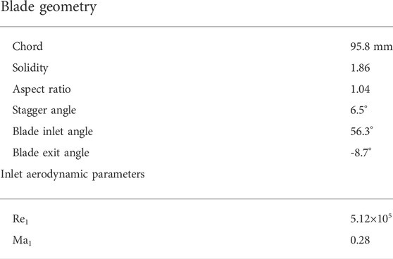
TABLE 1. Compressor cascade geometry and inlet aerodynamic parameters.

FIGURE 1. Schematic of blade geometry and computational domain.
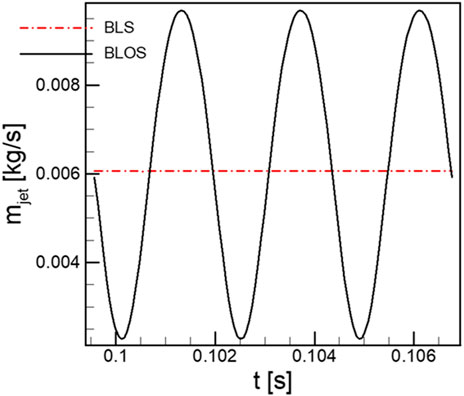
FIGURE 2. Periodic signal of the mass flow rate modeled by Eq. 1.
The computational domain is discretized into approximately 1.15 million finite volumes in the form of HOH-type structural meshes. In order to have higher resolution near the solid walls, grid nodes are concentrated near the walls, leading and trailing edges, which ensures that the global y + value is less than 5.
Flow fields for an analysis in this research are solved by ANSYS CFX v17.2. The second-order backward Euler method is used for time discretization, and the central difference JST scheme with suitable artificial viscosity achieves convective flow calculation with second-order accuracy. Approximation of the turbulent viscosity is carried out using a modified two-equation model RNG k-Epsilon, which will be compared with other models afterward.
For the incompressible flow problem in this study, the computational domain inlet is given in the total temperature, total pressure, and velocity directions. The inlet total pressure
Unsteady calculations are achieved by adding virtual time steps. Based on the intense unsteadiness and three-dimensionality in the compressor passage flow, a uniform time step of 1.0 × 10⁻⁵ has been set in the computation. The CFL numbers led by this configuration are controlled within 5.0. All the unsteady calculations use the results of steady calculations as the initial condition.
2.2 Numerical validation
This section is the validation of numerical calculation. We use the data provided by Soria and Cantwell (1993) as criteria to validate the numerical calculation configuration. The experimental parameters are shown in Table 2. During the numerical calculation of the high-load compressor, large-scale separated flow is bound to exist, and in order to be able to accurately describe the three-dimensional flow structure, the numerical parameter configurations in this study are set strictly based on the results of the numerical calculation calibration. These include the number of meshes, wall y + values, and the time and spatial discrete schemes.
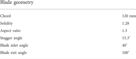
TABLE 2. Compressor cascade geometry and inlet aerodynamic parameters documented by Loughery et al. (1971).
The choice of turbulence is first examined. As shown in Figure 3B, the spanwise distribution of the pitch-averaged total pressure loss coefficient (defined by Eq. 2) calculated with the RNG k-Epsilon model matches better with the experimental data than other models. The comparison of the total pressure loss coefficient and the outlet Mach number is shown in Figure 4A, B, respectively, which can prove the accuracy of the numerical calculation results. In the spatial dimension Figure 3A, the separation topology, such as the onset and extent of the corner separation region, captured by ink flow visualization in the experiment, is remarkably predicted by the numerical results. Therefore, the present numerical configuration is reliable for revealing the flow characteristics in a high-load cascade.
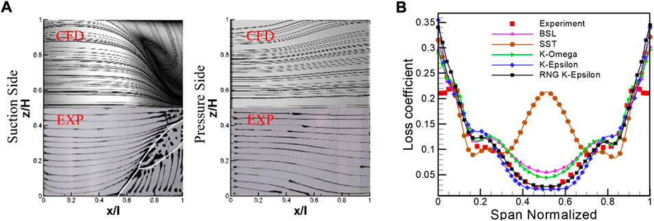
FIGURE 3. Validation of the 3-D simulation model. (A) Limiting stream lines of CFD and experimental results; (B) the spanwise distribution of total pressure loss coefficient at outlet.
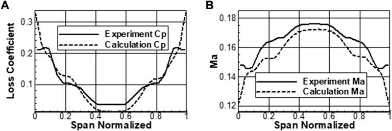
FIGURE 4. Total pressure loss coefficient and Mach number comparison. (A) Total pressure loss coefficient; (B) Mach Number.
The grid independence is investigated to ensure reasonability of the numerical configuration used in the current study. Figure 5 presents the variation of the total pressure loss coefficient with respect to the total grid numbers. The results show that further refinements (grid number larger than 1.15 million) of grids leads to less than 0.5% difference of loss coefficients, which indicates the consistency of the current simulations with respect to the variation of grid resolution.
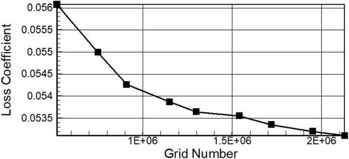
FIGURE 5. Grid independent validation of 3-D simulation.
3 Results and discussion
A detailed numerical analysis of the oscillation parameters and suction control parameters is presented in this section. Changes of the oscillating aspiration on the structure of the vortex are also investigated in depth. For a more accurate representation of the flow field structure, the Q-criterion, absolute value of the vorticity
Vorticity
where Q-criterion is used to identify vortex structures. Q is the second matrix invariant of the velocity gradient, which can be calculated using the following Eq. 4:
It can be seen that
The entropy production of turbomachinery can be divided into two parts: dissipative entropy production and heat transfer entropy production. The dissipation function
3.1 Influences of excitation parameters on control effects
3.1.1 The effect of excitation amplitudes
Figure 6 shows the variation of the total pressure loss coefficient with excitation amplitude. Both situations with f = 417 Hz and f = 1,000 Hz are considered here. The total pressure loss reaches 0.106 when Δms = 0.0, the BLS case. It can be seen that only when the excitation amplitude exceeds the threshold value of 0.2 does it have a significant positive effect on cascade performance. Optimal control is achieved in the following ranges from Δms = 0.316 to Δms = 0.7, with the maximum loss reduction approaching 8.42% for the case of f = 417 Hz. The change in frequencies, from 417 to 1,000 Hz, also affects the control effect, which can be concluded from the narrowed optimal region. It should be noticed that, beyond the optimal amplitudes, the control effects tend to deteriorate in both cases. Because of the inevitable introduction of additional viscous dissipation into the flow field, led by mass flow oscillation in the BLOS case, excessive increase in excitation amplitudes gives rise to more viscous loss and hence weakens the overall control effects.
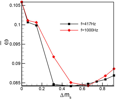
FIGURE 6. Distribution of total pressure loss according to the oscillation amplitude in the control of BLOS (0.39
The enhanced performance is indicative of promoted flow fields, which could be detected from flow topologies visualized by iso-surfaces of Q-value in Figure 7. In the BLS case Figure 7A, the separation vortices bearing the appearances of layer structures on the suction surface stably resides in the corner regions near the end walls. As the excitation amplitude approaches 5.98%, the layer-shaped separation vortices are forced to break down near the trailing edge, which can be attributed to the introduced unsteady effects by periodical oscillation in aspirating flow rates. Furthermore, the increased amplitudes, between 48.71 and 82.91%, tend to intensify the unsteady actuation in the separation vortices. The substantial change in the vortex structure due to BLOS is manifested in the splitting of the steady laminar separated vortex into a series of vortex tubes. These vortex tubes are simultaneously swept up by the lateral secondary flow near the end wall, forming a donut-like structure, and then periodically shed into the wake, which inevitably causes significant periodic oscillations in the flow field, thereby restoring the instability that the fluid inherently possesses.
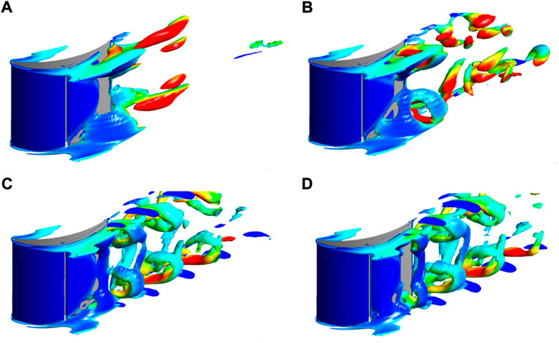
FIGURE 7. Instantaneous vortex structures of the cascade in the control with different oscillation amplitudes (Q =
It is the spatiotemporal alteration in vortical structures that distinguishes the control effects in the BLS and BLOS cases. More detailed discussions about the transformed separation topology and related performance variation will be presented subsequently.
3.1.2 The effect of excitation frequencies
The effect of another key control parameter, i.e., frequency on the control effect was investigated with an excitation amplitude of 48.71%. The variation of temporal-averaged total pressure loss coefficient is plotted in Figure 8. The uncontrolled case is used as a reference and is represented as a red circular solid dot in the aforementioned figure. The BLS and BLOS methods greatly improve the cascade performance by effectively mitigating large-scale separation in the uncontrolled flow field. The benefits of stabilized suction have been extensively documented in previous studies. The introduction of oscillations in the suction stream can further reduce losses within a certain optimal bandwidth. As labelled by red circular rings in Figure 8, the most effective controls are achieved in the range of f = 295 Hz through f = 1,326 Hz, with the maximum relative loss reduction approaching 20.5% of that in the BLS case. Beyond this range, the BLOS method no longer shows great advantages over the BLS method. This relative wide effective excitation bandwidth, discovered currently, indicates a large tolerance for choosing excitation frequencies in practical applications.
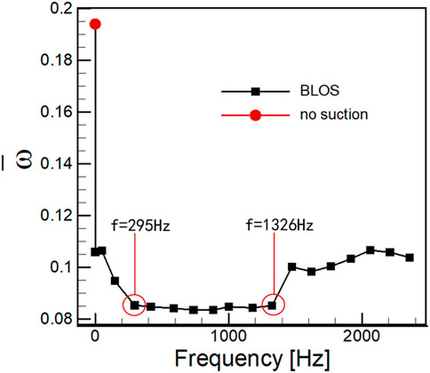
FIGURE 8. Distribution of total pressure loss according to the oscillation frequency in the control of BLOS (0.39
The temporal features of controlled flow fields with various excitation frequencies are revealed in Table 3. The five monitor points are placed at the streamwise location shown in Figure 1 and evenly distributed from 10 to 90% span. The time histories of total pressure captured by these monitor points are processed via fast Fourier transformation to extract the characteristic frequencies. As shown in the aforementioned table, the main frequencies captured in the flow field are in line with the excitation frequencies, which indicates that the unsteady properties in BLOS controlled flow fields are fully restrained by the oscillating aspiration flow rate. Furthermore, it could be argued that active flow control methods always have the tendency to impose some of their inherent physical properties on the flow field by means of mass, momentum, or energy exchange.

TABLE 3. Spectrum graph of total pressure with different excitation frequencies.
3.2 The response of effects to varied suction arrangement
An initial understanding about the process of boundary layer oscillation aspiration controlling a separation flow, especially the introduction of unsteady effect into the flow, is established in the previous section. The advantages possessed by BLOS over BLS in the control effects have also been proven to some extent. In this part, we perform further comparative investigations between BLS and BLOS on their susceptibility to varying operating conditions containing various suction flow rate, incidences, and suction locations.
3.2.1 The response to the mass flow rate of aspirations
The fundamental physical mechanism behind the boundary layer suction technique is to remove the low-energy fluid within the boundary layers. Achieving the most effective control at the lowest cost, mostly the aspirating flow rate, is always pursued, which can lead to the least impact on the main flow in cascades. In Figure 9, the performance variations with increasing aspirating flow rates for both BLS and BLOS cases are presented. In both cases, the suction control fails until the flow rate exceeds 1%. Afterward, both the control methods improve the performance of the cascade, with the BLOS method showing an advantage, with the largest relative loss reduction being 15.77% of that in the BLS case. This indicates that oscillatory suction is more effective than steady suction in controlling the separation flow at the same flow rate, or, from another point of view, the BLOS method can achieve the same control as the BLS case with a low suction flow rate.
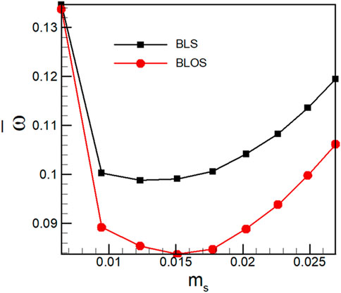
FIGURE 9. Distribution of time-averaged total pressure loss by the time-averaged suction mass flow in the control of BLOS and BLS.
3.2.2 The response to aspiration locations
To illustrate the influences of aspiration locations on the control processes, the performance variations for both BLS and BLOS cases with some selected parameters are shown in Figure 10. It can be observed that the effects led by the BLS method bear great sensitivity to the locations from Figure 10A. The enhancements only occur in a narrow location range of
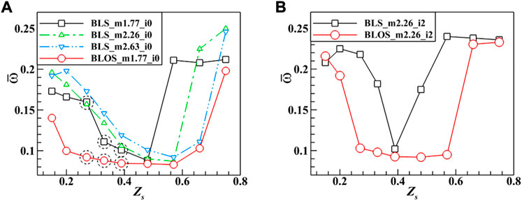
FIGURE 10. Distribution of time averaged total pressure loss according to the suction location in the control of BLOS and BLS. (A) ms = 1.77%, i = 0o and (B) ms = 2.26%, i = 2o.
On contrast, the BLOS method gives rise to suppression on the sensitivity of control effects to suction locations, which can be verified by the extended location range of
Another issue considered currently is to exclude the possibility that the aforementioned advantages of the BLOS method are resulted from the instantaneous increase in the suction flow rate during a half-oscillation period. Thus, in Figure 10A, we additionally present a BLS result with a suction flow rate equal to 2.63%, which is the peak value of the sinusoidally varied suction flow rate in BLOS. The result turns out that this BLS configuration still not only fails to effectively improve the performance to the same extent as the BLOS case, but even worsens the performance globally. The resultant conclusion could be drawn that the introduction of unsteady effects by the oscillating suction flow rate is the main cause of the superiority possessed by the BLOS method to the BLS one.
The different spatiotemporal alterations of separation structures for the BLS and BLOS cases are examined subsequently. The flow fields of cases, as labelled by dashed circles, with
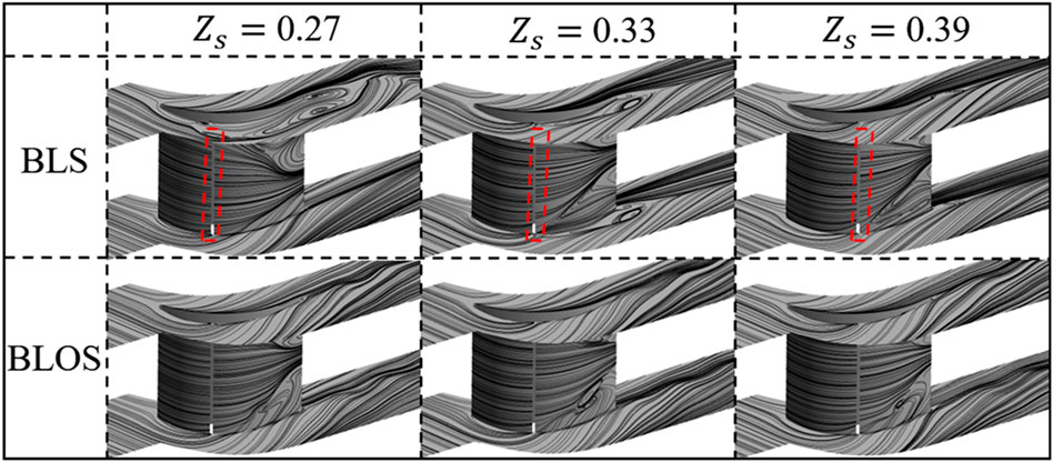
FIGURE 11. Instantaneous limiting streamlines by different suction locations in the control of BLOS and BLS.
The instantaneous vortical structures visualized in terms of Q iso-surfaces for selected cases are presented in Figure 12 in order to describe the entirely different vortical evolutions in the steadily and unsteadily controlled flow fields. The difference between the BLS and BLOS controlled flow fields manifests itself not in the structural transformations of the quasi-columnar vortices such as horse-shoe vortices and passage vortices but exclusively in the development of separation vortices on suction surfaces. In situations where the BLS method is adopted, the separation vortices on the suction surface show a relatively stable layer-shaped structure. The spatial extents of these structures shrink gradually as the control effects become strengthened from
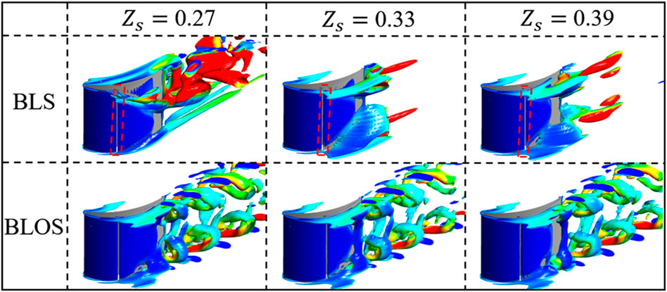
FIGURE 12. Instantaneous vortex structures by different suction locations in the control of BLOS and BLS.
3.3 Spatiotemporal alterations in separation flows
The differences in performance improvement between BLS and BLOS are direct reflections of vortical alterations in flow fields which have been briefly described in the previous section. The relation between transformed separation topologies and performance enhancement is emphasized in this section in order to advance our knowledge about the main cause of the different control effects.
The results with
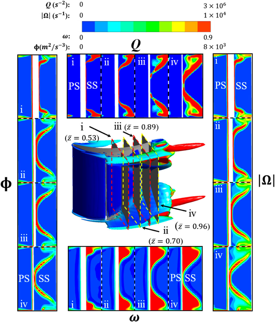
FIGURE 13. Instantaneous vortex structure and loss of stream-wise observing section in the control of BLS.
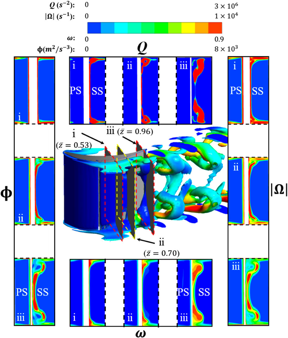
FIGURE 14. Instantaneous vortex structure and loss of stream-wise observing section in the control of BLOS.
In the BLS controlled flow field, the layer-shaped separation vortices consistently possess high vorticity from the onset to the later evolutionary stage according to both Figure 13(
For the BLOS case shown in Figure 14, vortical alterations induce different distributions of aerodynamic quantities. From the vortical evolution (slice 1 to 3) shown in Figure 14(
The aforementioned changes bring about significant reduction in pitch-averaged loss at the cascade outlet in the entire span as shown in Figure 15A. In streamwise direction, the distribution of averaged total pressure loss presented in Figure 15B reveals that the loss reduction takes place not only in the flow passage but also in the wake. Compared with the BLS case, the BLOS case causes a loss reduction of 17.5% at the trailing edge and 34.6% two axial chord lengths downstream the trailing edge. This denotes that the BLOS-induced vortex ring streets generate less viscous dissipation as convecting in the wake.
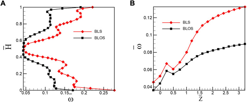
FIGURE 15. Span-wise distribution of pitch-averaged total pressure loss. (A) Stream-wise increase of overall mass-averaged total pressure loss and (B) in the outlet of cascade in the control with BLS and BLOS with the suction location of 0.33
Both the aspiration control methods are based on the effective removal of low-energy fluids. Moreover, the advantages possessed by the BLOS method in improving the cascade performance are achieved mainly through changing the layer-shaped separation vortices to the discretized donut-shaped vortex streets shedding into the wake. The benefits brought by the vortical transformation include (1) attenuated vorticity of separation vortices producing less local viscous dissipation; (2) narrowed blockage area trapping less low-energy fluids in the vicinity of corner regions; and (3) more energetic blockage fluids contributing to the mixing loss reduction in the wake.
4 Conclusion remarks
Simulations of the flow of a three-dimensional linear high-load compressor cascade controlled by the BLS and BLOS methods were carried out. The effect of oscillation parameters on the control effect was parametrically investigated. In addition, a comparative analysis of the sensitivity of the BLS and BLOS methods to different operating conditions was carried out. This work was performed to understand the basic aerodynamics of unsteady suction for controlled flow separation.
4.1 Control parameters
Oscillation amplitude and frequency are two crucial control parameters. The amplitude represents the energetic level of the unsteady excitation. Only when it exceeds a certain threshold can the BLOS method take effect, and in this study, the threshold value equals 0.31 approximately. However, due to the additional viscous dissipation introduced, excessive amplitudes weaken the control effect. A relative wide optimal frequency bandwidth within which the BLOS method surpasses the BLS method is detected in the current study. Also, in these situations, the characteristic frequency of the flow field is locked up to the excitation frequency.
4.2 Susceptibility to varying conditions
The BLOS method shows advantage over the BLS method on the control cost and the susceptibility to varying working conditions. With a fixed effective suction flow rate, the BLOS method can result in higher loss reduction. The variation in suction locations affects the BLOS controlled cascades less significantly than that with the BLS method. The operating range in terms of incidences is highly extended due to introduction of oscillation into the aspiration.
4.3 Flow structures
Oscillatory aspiration takes over the advantages of steady aspiration and further introduces structural reorganization in the flow field. The spatial transformation is mainly reflected in the discrete laminar separation vortex into a donut-shaped vortex street shedding to the wake flow. The vortical alteration leads to lower vorticity of separation vortices and hence decreases the viscous shear stress. The cascade blockage is also alleviated, indicating less low-energy fluids bounded in the corners. Furthermore, the donut-shaped vortex street contributes to the reduction in mixing loss in the wake.
Data availability statement
The original contributions presented in the study are included in the article/Supplementary Material; further inquiries can be directed to the corresponding author.
Author contributions
BL completed most of the numerical simulation work and processed and analyzed the numerical results; LC proposed the method of boundary layer oscillating suction; HX jointly completed the analysis of the numerical simulation results; HF jointly completed part of the analysis of the results and drew part of the charts; and SW gave theoretical guidance to numerical simulation and result analysis.
Conflict of interest
The authors declare that the research was conducted in the absence of any commercial or financial relationships that could be construed as a potential conflict of interest.
Publisher’s note
All claims expressed in this article are solely those of the authors and do not necessarily represent those of their affiliated organizations, or those of the publisher, the editors, and the reviewers. Any product that may be evaluated in this article, or claim that may be made by its manufacturer, is not guaranteed or endorsed by the publisher.
References
Culley, D. E., Bright, M. M., and Prahst, P. S. (2003). “Active flow separation control of a stator vane using surface injection in a multistage compressor experiment,” in Proceedings ASME Turbo Expo 2003, collocated with the 2003 International Joint Power Generation Conference, Atlanta, Georgia, USA, February 4, 2009 (American Society of Mechanical Engineers), 1039–1050. doi:10.1115/GT2003-38863
Culley, D. E., Bright, M. M., and Prahst, P. S. (2003). Active flow separation control of a stator vane using surface injection in a multistage compressor experiment. Washington, DC: ASME Paper.
Dorfner, C., Hergt, A., and Nicke, E. (2011). Advanced nonaxisymmetric endwall contouring for axial compressors by generating an aerodynamic separator—Part i: Principal cascade design and compressor application. ASME J. Turbomach. 133, 021026. doi:10.1115/1.4001223
Guendogdu, Y., Vorreiter, A., and Seume, J. R. (2008). “Design of a low solidity flow-controlled stator with coanda surface in a high speed compressor,” in Proceeding ASME Turbo Expo 2008: Power for Land Sea, and Air, Berlin Germany, August 3 2009 (American Society of Mechanical Engineers), 629–639. doi:10.1115/GT2008-5118011
Gümmer, V., Goller, M., and Swoboda, M. (2008). Numerical investigation of end wall boundary layer removal on highly loaded axial compressor blade rows. J. Turbomach. 130 (1), 011015. doi:10.1115/1.2749297
Hamrin, M., Gunell, H., Lindkvist, J., Lindqvist, P.-A., Ergun, R. E., and Giles, B. L. (2018). Bow shock generator current systems: MMS observations of possible current closure. JGR. Space Phys. 123 (1), 242–258. doi:10.1002/2017JA024826
Kerrebrock, J. L., Epstein, A. H., Merchant, A. A., Guenette, G. R., Parker, D., Onnee, J. F., et al. (2008). Design and test of an aspirated counter-rotating fan. J. Turbomach. 130 (2), 021004. doi:10.1115/1.2776951
Kerrebrock, J. L., Reijnen, D. P., Ziminsky, W. S., and Smilg, L. M. (1997). “Aspirated compressors,” in Proceedings ASME 1997 International Gas Turbine and Aeroengine Congress and Exhibition, Orlando Florida USA, December 24, 2014 (American Society of Mechanical Engineers.). doi:10.1115/97-GT-525
Le, C. (2015). Investigation on separation structure and its steady & unsteady control in low reaction high load compressor cascade. China: Harbin Institute of Technology.
Lee, M. U., Ji, J.-Y., and Yun, G. S. (2020). Cold-hot coupled waves in a flowing magnetized plasma. Nucl. Fusion 60, 126036. doi:10.1088/1741-4326/abb61a
Loughery, R. J., Horn, R. A., and Tramm, P. C. (1971). Single stage experimental evaluation of boundary layer blowing and bleed techniques for high lift stator blades. Washington, D.C.: NASA CR-54573.
Merchant, A. A. (2000). “Aerodynamic design and analysis of a high pressure ratio aspirated compressor stage,” in Proceeding ASME Turbo Expo 2000: Power for Land, Sea, and Air, Munich, Germany, August 4, 2014 (American Society of Mechanical Engineers.), 10. doi:10.1115/2000-GT-0619
Pawan, S., Santosh, K. S., and Harekrishna, Y. (2022). Experimental investigation of flow and thermal characteristics of synthetic jet issuing from sharp-edged orifices. Exp. Heat. Transf. 9, 1–25. doi:10.1080/08916152.2022.2105449
Schlaps, R. C., Shahpar, S., and Gümmer, V. (2014). “Automatic three-dimensional optimisation of a modern tandem compressor Vane,” in Proceedings of ASME TURBO, 2014, Düsseldorf Germany (ASME). doi:10.13140/2.1.2633.6007
Seifert, A., Darabi, A., and Wyganski, I. (1996). Delay of airfoil stall by periodic excitation. J. Aircr. 33 (4), 691–698. doi:10.2514/3.47003
Siemann, J., and Seume, J. R. (2015). “Design of an aspirated compressor stator by means of doe,” in Proceeding ASME Turbo Expo 2015: Turbine Technical Conference and Exposition, Montreal Quebec Canada, August 12, 2015 (American Society of Mechanical Engineers.), 13. doi:10.1115/GT2015-42474
Song, Y. P., Chen, F., Yang, J., and Wang, Z. Q. (2005). A numerical investigation of boundary layer suction in compound lean compressor cascades. Turbine technical conference and exposition. USA. New York: ASME.
Soria, J., and Cantwell, B. J. (1993). Identification and classification of topological structures in free shear flows. Eddy Struct. Identif. Free Turbul. Shear Flows 21, 379–390. doi:10.1007/978-94-011-2098-2_31
Sushanta, D., and Shantanu, (2022). Effects of the synthetic jet on the flow field and heat transfer over a surface-mounted square rib. Exp. Therm. Fluid Sci. 139, 110708. doi:10.1016/j.expthermflusci.2022.110708
Vandeputte, T. W. (2000). Effects of flow control on the aerodynamics of a tandem inlet guide vane, Master’s thesis. Blacksburg, Virginia: Virginia Polytechnic Institute and State University.
Vytenis, M. (2020). Magnetosphere: From plasma observations to reconnection theory. J. Geophys. Res. Space Phys. 125 (9), JA027865. doi:10.1029/2020JA027865
Wang, S., Qiang, X., and Feng, G. (2007). “Highly-loaded low-reaction boundary layer suction axial flow compressor,” in Proceeding ASME Turbo Expo 2007: Power for Land, Sea, and Air, Montreal, Canada, March 10, 2009 (ASME), 405–412. doi:10.1115/GT2007-28191
Zhang, L., Du, X., and Liu, X. (2016). “3D unsteady simulation of a low speed low-reaction aspirated compressor,” in Proceeding ASME Turbo Expo 2016: Turbomachinery Technical Conference and Exposition, Seoul South Korea, September 20, 2016 (American Society of Mechanical Engineers.). doi:10.1115/GT2016-56888
Zheng, J. G., Zhao, Z. J., Li, J., Cui, Y. D., and Khoo, B. C. (2014). Numerical simulation of nanosecond pulsed dielectric barrier discharge actuator in a quiescent flow. Phys. Fluids 26 (3), 036102. doi:10.1063/1.4867708
Nomenclature
Abbreviations
AOA Angle of attack
AVDR Axial velocity density ratio
BLS Boundary layer suction
BLOS Boundary layer oscillation suction
CFD Computational flow dynamics
SST Shear stress transport
DES Detached eddy simulation
LES Large eddy simulation
TE Trailing edge
Keywords: compressor cascade, boundary layer, oscillating suction, separated flow control, vortex structure
Citation: Liu B, Cai L, Xu H, Fu H and Wang S (2022) Numerical investigations on oscillating aspirations controlling separation flows in linear highly loaded compressor cascades. Front. Energy Res. 10:989883. doi: 10.3389/fenrg.2022.989883
Received: 09 July 2022; Accepted: 05 September 2022;
Published: 21 September 2022.
Edited by:
Kaiqiang Zhang, Imperial College London, United KingdomReviewed by:
Xiaoxu Kan, Shanghai Maritime University, ChinaShaopeng Lu, Shanghai Jiao Tong University, China
Hongxin Zhang, Nanjing University of Aeronautics and Astronautics, China
Copyright © 2022 Liu, Cai, Xu, Fu and Wang. This is an open-access article distributed under the terms of the Creative Commons Attribution License (CC BY). The use, distribution or reproduction in other forums is permitted, provided the original author(s) and the copyright owner(s) are credited and that the original publication in this journal is cited, in accordance with accepted academic practice. No use, distribution or reproduction is permitted which does not comply with these terms.
*Correspondence: Le Cai, ZWFyY2xlQHllYWgubmV0