 T. Ravi
 K. Sathish Kumar
- School of Electrical Engineering, Vellore Institute of Technology, Vellore, Tamil Nadu, India
Despite the numerous benefits of distributed generation (DG), such as reliable energy supply and environmental friendliness, there are a number of challenges associated with integrating DG with the grid. In the field of DG, the complication of power quality (PQ) is a major technical challenge. Custom power devices (CPDs) are used in the distribution system to solve complications. This study presents different PQ disturbances (PQDs), monitoring techniques, and fundamental standards. Furthermore, with the widespread literature, the study critically reviews different PQ mitigation techniques such as distribution static compensator (DSTATCOM), dynamic voltage restorer (DVR), unified power quality conditioner (UPQC), and uninterruptable power supply (UPS). The present research work is not only limited to surveying the existing techniques but also analyzing the performance of UPQC using the ANFIS controller. Overall, this study is intended to provide researchers working on improving PQ in the distribution system with a valuable resource that will aid them in enriching their research.
1 Introduction
1.1 Background and motivation
Conventional electricity generation plants, such as coal-fired, nuclear, and hydroelectric power plants, experience various problems, including scarcity of fossil fuels, significant greenhouse gas emissions, and transmission line power loss. Distributed generation has the potential to address these issues while also assisting in meeting the ever-increasing load demand (Pepermans et al., 2005). Uncertainty is a significant issue with distributed energy resources (DER), causing a number of problems in the distribution systems. 1) It exacerbates the strain on the transmission network. 2) It establishes complicated supply–demand relationships. 3) This could result in the reversal of power flow from the distribution system to the transmission system (De Carne et al., 2018; Zhang et al., 2020).
Distributed generation (DG) or shunt reactive compensators are common compensatory methods (SRCs). Four types of DG units exist: Type 1, which involves injecting only active power into the network, such as PV and fuel cells; Type 2, which offers just reactive power, such as no-load synchronous motors; Type 3, which produces both active and reactive power, such as a synchronous generator or microturbine, and Type 4, which provides active power but consumes reactive power, such as an induction generator-based wind energy system. SCRs inject reactive power into distribution networks. SRCs are shunt capacitor banks, static VAR compensators, or distribution static compensators (DSTATCOM). The DSTATCOM is the most costly and sophisticatedly regulated device utilized in higher power applications. Size, cost, and control place the static VAR compensator (SVC) between the shunt capacitor (SC) and DSTATCOM.
The term “power quality” refers to an electric power system ability to maintain the rated amplitude and frequency of noise-free sinusoidal voltage and current. The primary sources of PQ issues are switching operations, faults, and lightning on the utility side, whereas nonlinear loads, inadequate grounding, electromagnetic interference, and static electricity on the end-user side present a variety of technical challenges. Power quality is a significant issue that affects almost all industrial, commercial, and residential customers. Figure 1 shows the results of a survey on the causes of PQ problems conducted by Georgia Power Company from the perspective of utility and customers (Bhadane et al., 2012). Various PQ issues that the grid encounters include voltage sags, swells, harmonics, load shedding, and so on. Some PQ issues have a detrimental effect on the protection system, resulting in malfunctioning protective devices. These factors also have an effect on the various measurement instruments and monitoring systems.
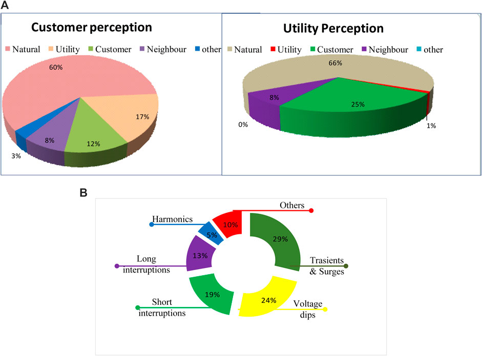
FIGURE 1. (A) Results of a survey on the causes of PQ problems conducted by Georgia Power company. (B) Major PQ issues study conducted by GreenTree Global team.
Voltage disturbances are a significant PQ issue that requires regulation. Regulation of voltage is dependent on the generator excitation system and reactive power compensation (Muljadi and McKenna, 2001). CPDs are primarily used in DS to reduce PQDs and improve PQ (Ghosh and Ledwich, 2002). Figure 1B illustrates a market research and an analysis study conducted by the GreenTree Global team on major issues affecting PQ, market sizing, and trends for 2018–21 (Power Quality Monitoring: Market Landscape Assessment, 2022). According to this, over 50% of the causes of PQ degradation are voltage dips, transients, and spikes.
1.2 Literature review
Since the early 1990s, researchers have integrated DG or SRC units into distribution networks for various purposes. These objectives were to reduce power loss by mitigating line currents, maximizing voltage stability, and improving power quality. The researchers used several methodologies and methods to allocate DG or SRC units in distribution systems. Reactive power injection reduces source’s reactive current and the feeder current. Power loss and voltage profile improve. The shunt capacitor is the simplest device to inject reactive power. Shunt capacitor (SC) core issues are fixed reactive power and bus voltage dependence.
In the conventional distribution system, power filters (PFs) have been used to mitigate PQDs. Passive power filters (PPFs) are used to reduce harmonics in traditional power systems due to their low cost and simplicity. However, PPFs are extremely sensitive to parallel resonance due to the capacitors low rating (Kashif et al., 2020). However, disadvantages such as large size, fixed compensation, and susceptibility to resonance can be avoided by utilizing equipment referred to as an active power filter (APF). Additionally, APFs filter out both higher- and lower-order harmonics (He et al., 2017). Shunt APFs and series APFs are two forms of APFs. Both the series and shunt APFs are designed to lower total harmonic distortion (THD) in the voltage and current, respectively. The UPQC is a hybrid of series and shunt APFs that is designed to simultaneously suppress multiple PQ problems (Nabavi-Niaki and Iravani, 1996; El-Habrouk et al., 2000). An UPS can also be used to mitigate PQ problems. It provides emergency power to critical loads in the event of a power outage. Generally, UPSs are used to safeguard hardware such as computers, telecommunications, and data center equipment (Yeh and Manjrekar, 2007; Aamir et al., 2016). Any power electronics-based system relies heavily on its control strategy. The control strategy of a system determines its behavior and desired operation. The control approach validates the reference current and voltage signals and, thus, elects the converter switching moments to achieve the desired performance. The term “flexible alternating current transmission system” (FACTS) is a commonly used term in AC transmission. One or many system parameters can be adjusted to enhance the systems controllability while simultaneously increasing system’s capacity for power transmission (Edris et al., 1997). The STATCOM is a member of the FACTS family that provides reactive power at low voltages, improving the voltage profile. Additionally, due to the DC capacitor, it has a very low active power capability. Moreover, it has a faster switching time than a static VAR compensator (SVC) because of the IGBTs used in voltage source converter (VSC)-based STATCOM (Singh et al., 2009; Al-Nimma et al., 2011). Agarwal et al. (2017) developed a leaky least mean fourth (LLMF) control method for a three-phase single-stage grid integrated solar photovoltaic distributed static compensator (SPV-DSTATCOM). For the extraction of fundamental active and reactive loss components and load currents, feed-forward SPV power, extraction of in-phase, and quadrature unit templates are used to produce the grid’s reference currents. To determine the terminal voltage amplitude, the LLMF method is necessary.
1.3 Contributions
The primary purpose of the study is to give a comprehensive analysis of power quality problems and provide possible solutions to these problems. This study covers a detailed examination of the power quality in power systems, including those with DC and renewable sources, and the standards that describe these concerns. The analysis was carried out by the authors of this study. Methods for evaluating the power quality and possible improvements to the power quality of power systems are both being thoroughly researched. In summary, a comprehensive analysis of power quality problems together with their monitoring, mitigation, and control techniques of CPDs as a whole is presented in a single body of work.
1.4 Article organizations
This article focuses mostly on power quality disturbances. The following sections discuss various PQ issues that can occur in both alternating current (AC) and direct current (DC) systems. Section 2 discusses PQ monitoring systems and various PQ mitigation techniques (such as DSTATCOM, DVR, UPQC, and UPS), and the review on various controllers of CPDs are presented. PQ standards such as IEEE and IEC are presented in Section 3. A proposed PQ improvement technique has been described in Section 4. Section 5 contains overall review on PQ mitigation techniques, and Section 6 provides the conclusion.
1.5 Typical PQ issues
Various PQ issues that occur in the AC system are classified according to the IEEE 1159 standard and illustrated in Figure 2 using a tree diagram.
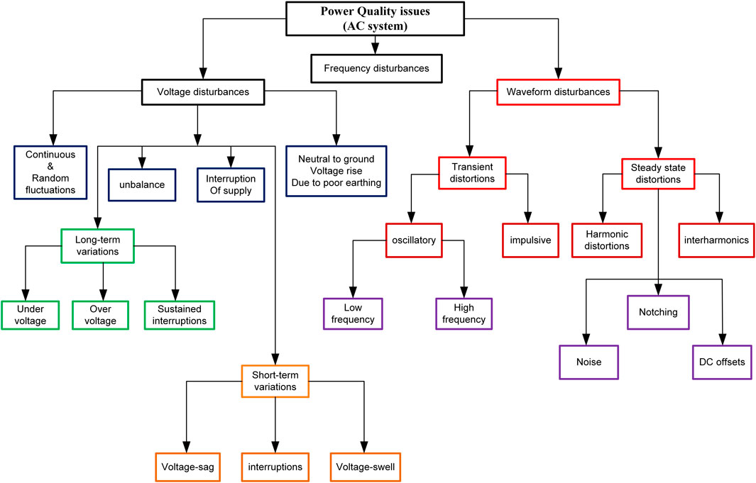
FIGURE 2. Classification of PQ problems.
1.6 PQ issues in AC systems
To highlight the impact of PQDs, we might state that poor PQ results in significant energy and economic waste. It burdens both suppliers and consumers financially. Voltage and frequency fluctuations frequently disrupt the flow of electricity through transmission lines. “Voltage fluctuation” denotes variations in voltage amplitude. A transient is a short-lived energy surge (Rönnberg and Bollen, 2016). It is usually caused by a sudden change of state, such as surges. Voltage, current, or both may undergo an abrupt shift in their steady-state conditions. Voltage sag refers to the decrease in magnitude of the supplied voltage (Styvaktakis et al., 2000). The voltage swell phenomenon refers to a transient rise in voltage that exceeds standard tolerance thresholds. It normally lasts less than a few seconds and has duration of more than one cycle (Ma et al., 2021). Harmonics are voltage or current waveform distortions generated by nonlinear loads. “Long time voltage interruption” is another significant PQD (Sarangi, 2020). This issue refers to the interruption or reduction of the voltage or load current for durations ranging from a few milliseconds to 1 or 2 s (Ma et al., 2021). This type of issue causes data processing devices to malfunction. Distortion of the waveform is a steady-state variation from an ideal sine wave of power frequency. DC offset harmonics, interharmonics, notching, and noise are the most common kinds of waveform distortion (Gupta et al., 2021). “Frequency variation” is the deviation of the fundamental frequency of a power system from its nominal value (50 Hz or 60 Hz). Figure 3 illustrates the major PQ disturbances with waveforms, and the summary of power quality disturbances in AC systems is depicted in Table 1.

FIGURE 3. Waveforms of various power-quality issues.
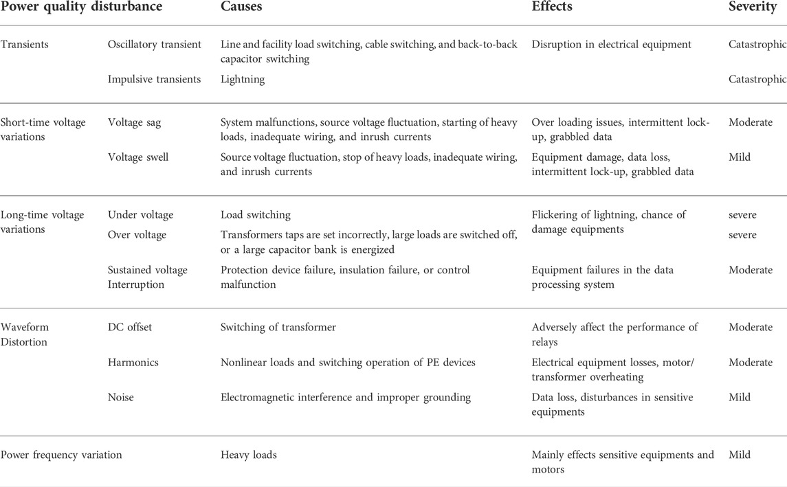
TABLE 1. Summary of power quality disturbances in the AC system.
1.7 PQ issues in DC systems
Power quality challenges in DC systems are distinct from AC PQ issues. A power converter is the main component of a DC system. Because PE converters switch, they introduce voltage and current harmonics into the system. There are four types of PQDs in a DC system: fault current, inrush current, harmonic current, and grounding.
1.7.1 Inrush current
When a power source is turned on, it draws a large initial current. This is an “inrush current.” In a DC system, inrush currents are associated with the initiation of an IM or transformer. By contrast, PE converters connect the DC link to the load (Hoshi et al., 2012). The waveform of an inrush current is shown in Figure 4A with an electromagnetic interference (EMI) filter. The EMI filter will use capacitance C1 across the input line. The DC–DC converter will have capacitance C2 and C3 on both sides. Auxiliary capacitance C4 could be used across the load. Each of these capacitors needs current to maintain its stable voltage at SS. A surge current occurs when the input supply is turned on. This peak current fully charges C1 and C2. The second crest current occurs when the DC–DC converter is turned on, charging C3 and C4 to SS values (Asakimori et al., 2014). High inrush currents can cause system voltage sags, affecting other devices. Transitive
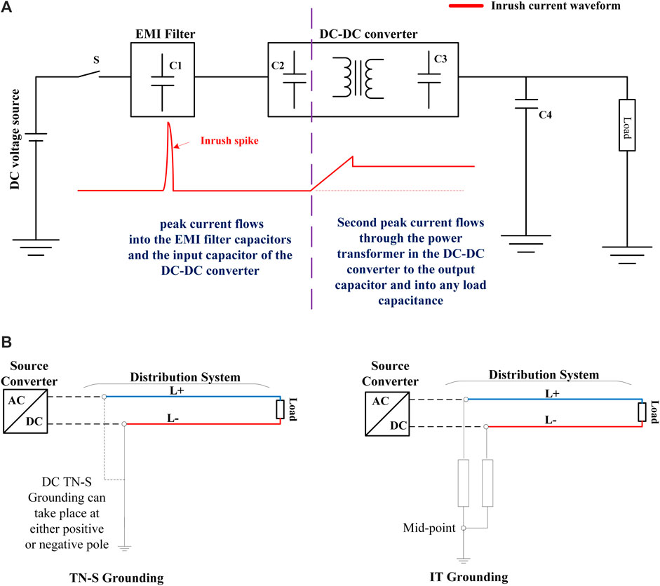
FIGURE 4. (A) Typical DC system with EMI filter and inrush current waveform. (B) TN-S and IT grounding concepts for DC distribution systems.
1.7.2 Fault current
Faults in an AC system usually do not affect voltages due to impedance. However, DC system faults affect voltage and must pass through DC bus converters or power supplies, limiting fault current (Kwasinski and Onwuchekwa, 2011). Limiting faults reduce system stress by avoiding a transient voltage spike, whereas reducing available fault current increases network voltage disturbance (He and Li, 2011). Overcurrent relays are often employed to protect devices. Low fault current makes protection settings difficult to find. This increases inrush current, which must be decreased by soft-starting or charging in advance (Giancaterino, 1994).
1.7.3 Harmonic current
As stated previously, systems have no harmonic currents or voltages in DC circuits. Except for the fundamental frequencies, a DC system has many frequencies that are integer multiples of 0 Hz. However, the presence of oscillations (current, voltage, or both) in a DC system necessitates the generalization of harmonic analysis to DC systems (Zhang et al., 2000). There are filters to decrease harmonics and voltage oscillations in DC systems. Filters should be used in HVDC system design to reduce harmonic and circulating currents (Bierhoff and Fuchs, 2008). Resonant damage is also a problem in low-DC-voltage systems. Low-DC-voltage systems can have undesirable resonant currents, EMI, and voltage variations; hence, a thorough harmonic analysis is required (Liang et al., 2021).
1.7.4 Grounding/earthing
While grounding protects against lightning, it also protects against electrical shocks from exposed metal parts. Figure 4B shows the TN-S and IT earthing ideas for the DC distribution system. DC system grounding affects PQ and protects greatly during fault circumstances. TN-S earthing is used to connect one of the poles to protective Earth at low DC voltages. This method restricts the voltage on a line-to-ground failure and halves the system voltage to ground for high DC voltages, such as 380 or 400 V, providing improved safety over the TN-S method (Wannurzana, 2010).
2 Power-quality monitoring and mitigation techniques
2.1 Overview of the power quality monitoring system
Figure 5 illustrates a block diagram of a typical PQ monitoring system. Data acquisition, communication, and data visualization are the three main stages of the system. Current transformers (CTs), potential transformers (PTs), and transducers (XD) are used as sensors in the data acquisition stage to measure electrical and nonelectrical parameters. Voltage and current measurements are converted to digital signals using digital circuits such as multiplexers (MUX), analog-to-digital converters (ADCs), and sample and hold (S & H) circuits. To protect against extremely erratic PQ disturbance, data should be continuously recorded and processed, increasing memory requirements. The trigger engine determines which and how much data to save in the database (DB) (Divyalakshmi and Subramaniam, 2017). Real-time data are time synchronized to the required level of accuracy for the application. There are multiple time synchronization techniques, including the use of GPS, Inter-Range Instrumentation Group (IRIG), and Network Time Protocol (NTP) RFC-5905 (Bingham, 2001).
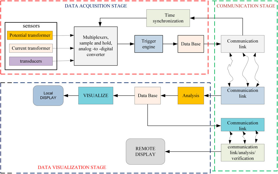
FIGURE 5. Typical PQ monitoring system.
Data are transferred between communication centers in the second stage. IEEE standard 1159.3-2009 (Cookson and Stirk, 2019) standardizes PQ data transmission based on the EPRI (Electric Power Research Institute) (IEEE std 1159.3, 2004). Finally, the PQ monitoring system visualizes data as time plots. Nowadays, a variety of software applications are used to analyze and visualize large amount of data. Remote visualization can usually happen via web browsers. This method of visualization has alleviated some issues with running proprietary software on user’s PCs, including conflicts and upgrades.
The process of evaluating PQ is depicted in Figure 6. The evaluation process begins by classifying the problems. The first stage includes transients, harmonics, flicker, voltage unbalance, and voltage interruption. The second stage is problem characterization, which can be accomplished through measurements or data collection to ascertain the causes, characteristics, and impact of equipment. After defining the problem, it is necessary to revisit the equipment design or specifications, end-user customer interface, end-user customer system, utility transmission, and distribution system in order to determine the range of possible solutions. The following step is to evaluate the solutions. In this section, modeling or analysis procedures are used to evaluate technical alternatives. The final step is to evaluate the economics of the best solution.
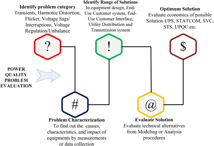
FIGURE 6. The process of evaluating the power quality.
2.1.1 PQ monitoring and analysis tools
As previously stated, harmonics hinder the electric networks PQ and harm equipment’s safety. Enhancing PQ is the primary goal of harmonic signal compensation. Numerous harmonic analysis tools exist to improve the quality of power, including the fast Fourier transform (FFT), singular value decomposition (SVD), and artificial neural network (ANN), among others. When using the FFT for a harmonic analysis of power systems, the method of synchronized sampling and integral period truncation has some issues. Frequency, phase, and amplitude have all been found and corrected with FFT several times, including using window functions and interpolation algorithms. To address several flaws in existing correction methods, Dugan et al. (2017) proposed an improved algorithm. The SVD technique is a highly reliable and computationally stable mathematical technique for solving rectangular over determined systems of equations. Additionally, the method can be used to calculate the fundamental frequency of highly distorted periodic signals. However, the SVD computation is significantly more complex than the FFT computation and requires additional numerical manipulations (Hossain et al., 2018). Zeng et al. (2011) proposed a novel method for measuring power harmonics based on an artificial neural network (ANN). It analyzes and calculates the three-phase current for the current and previous sample times using a multilayer feed-forward neural network (MLFNN) and then extracts the harmonic components of the three-phase current. The NN structure is discussed, as is the learning algorithm used to train it.
Monitoring is necessitous not exclusively for reliability indices and power flows but also for the nonsinusoidality of the supply voltage waveform. The usage of phasor measurement units (PMUs) can significantly enhance the observability of electric power systems (Lobos et al., 2006). LabVIEW, a monitoring and analysis tool, was also developed. To predict the harmonics of a power system, we use the “ADALINE (Adaptive Linear Neuron)” neural network. ADALINE has three sequences: input, output, and a desired response sequence. Additionally, it has an adjustable parameter called the weight vector. To create the Fourier coefficients of the ADALINE signal, the signals’ weight vector is adjusted nonlinearly based on a stable difference error equation (Dash, 1996). Wavelet transform (WT) is one of most powerful approaches for extracting features because it incorporates a multiresolution analysis (MRA) approach. WT is superior to FT in numerous ways (Moravej et al., 2010). Using the estimated and detailed WT coefficients, numerous statistical parameters of PQD signals, such as amplitude, mean, median, energy, standard deviation, and entropy, can be computed. Over the last 2 decades, numerous researchers have extensively used three variants of WT to recognize PQ disturbances: continuous WT (CWT), discrete WT (DWT), and wavelet packet transform (WPT) (Nath et al., 2012).
The Hilbert transform (HT) operator is a linear one and used to trace the signals’ amplitude envelope. When applied to real data, the HT will turn a sequence of these actual numbers into an analytical signal with two separate components: one component with the original numbers and another is an imaginary component containing the Hilbert transform. An imaginary version of the original sequence is created by a 90° phase shifting. In order to identify the instantaneous attributes of a time series, specifically the amplitude and frequency, the Hilbert transform is useful. Hilbert transform works a lot faster than wavelet transform because it does not require an exhaustive testing of all possible wavelet families (Jayasree et al., 2010).
2.2 PQ mitigation techniques
Power quality disturbance mitigation is required to guarantee the efficient and secure functioning of sensitive equipment, particularly for distributed generating networks connected to the grid. The daily increment of nonlinear loads (NLs) in these networks aids utilities in reducing electrical consumption by removing inefficient, large loads. These NLs are more productive because of their electronic front ends, but they considerably increase the harmonic injection into the distribution network. In general, CPDs are used in the distribution system to mitigate different PQ issues, whereas FACTS devices are utilized in transmission networks to address the problem of low PQ. DSTATCOM, DVR, and UPQC may be designed with a variety of topologies, which are primarily categorized by the following: 1. distribution system (3P3W and 3P4W), 2. arrangement of the power electronic switching devices, and 3. type of converter employed. In addition, the 3P3W and 3P4W devices are separated into isolated and nonisolated systems depending on the transformer used to ensure total isolation between the VSC and the supply, as well as neutral current compensation. Typical transformer topologies include star-delta, zigzag, T-connected, and star-hexagon. In this section, some PQ mitigation techniques such as STATCOM, UPQC, and UPS are addressed (Sao et al., 2002; Milanović and Zhang, 2010; Madhana and Mani, 2022).
2.2.1 Distribution static compensator
To enhance PQ, DSTATCOM (shunt-connected CPD) is commonly utilized in DS (Yusuf, 2004). It has propensity to inject and observe reactive power at a faster rate due to presence of high switching frequency IGBT, which supports PF correction, improving voltage profile and voltage. Also, it can provide harmonic filtering and reduce fluctuations caused by the PV system, which increases PV installation (Chen et al., 2013). Figure 7 shows the DSTATCOM system connected to PCC (DSTATCOM system configured with a coupling transformer, inverter, and battery energy storage system). A DSTATCOM generates an adjustable AC voltage source from a DC capacitor (energy storage device) and a voltage source inverter (VSI) (Latran et al., 2015). The AC voltage source appears behind a transformer leakage reactance. Voltage differential across reactance causes active and reactive power transfer between feeders and DSTATCOM. The DSTATCOM is connected to electric networks where the voltage-quality challenge is a concern. All voltages and currents are monitored and supplied to the controller for comparison with directives. The controller provides a feedback control and produces switching signals to operate the primary semiconductor switches (IGBTs) of the power converter (Sirjani and Rezaee Jordehi, 2017). The classification of D-STATCOM topologies are as follows:
1. Three-phase three wire (3P3W)
A. Nonisolated
a. Three leg voltage source converters.
b. Two leg voltage source converters with split capacitor
B. Isolated
a. Three single-phase VSC topology
b. Isolated three leg system
c. Isolated two leg system
2. Three-phase four wire (3P4W)
A. Without transformer
a. Four leg VSC
b. Three leg VSC
B. With transformer nonisolated
a. Three leg VSC
b. Two leg VSC
C. With transformer isolated
a. Three leg VSC
b. Two leg VSC
c. Three single-phase VSC
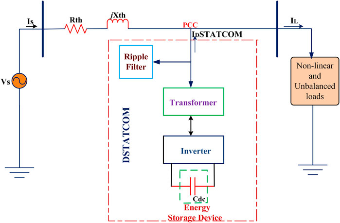
FIGURE 7. System configuration of DSTATCOM.
2.2.1.1 Survey on optimal allocation of distribution static compensator and control strategies
Rezaeian Marjani et al. (2019) proposed a multiobjective optimization algorithm based on particle swarm optimization (MOPSO). The voltage profile index, load-ability index, and active power loss are esteemed as objectives in optimization practice. In the suggested strategy for identifying the final solution, technique for order performance by similarity to ideal solution (TOPSIS) was utilized. Objective functions in Hussain and Subbaramiah (2013) consisted of power loss and voltage profile. An analytical method was developed and tested in a 33-bus radial system. Also, the result of proposed method was compared with a genetic algorithm (GA). In Bagheri Tolabi et al. (2015), ant colony optimization (ACO) has been utilized for appropriate placement of DSTATCOM in the combination of PV array in an attempt to minimize true power losses, optimize voltage profile, and establish load balancing on feeders. In 2014, Akbari-Zadeh et al. (2014) employed bat swarm optimization algorithm to find location of D-STATCOM for load uncertainty. The effect of uncertainty loads can be modeled using a new stochastic structure for D-STATCOM allocation and sizing difficulties. The presented design was validated on IEEE 69-bus DS. Roy et al. (2013) examined the impact of D-STATCOM in reactive power management with wind generation to improve voltage stability. Taher and Afsari (2014) presented the immune algorithm (IA) to decide the best allocation of D-STATCOM with the following objective functions: 1) reduce power loss and 2) improve voltage and current profile in DS. Allocation and sizing of D-STATCOM were performed using the harmony search (HS) algorithm, in which copper loss minimization is considered as an objective. The described methodology has been tested on IEEE 33-bus DS. The results show the outperformance of the proffered HS algorithm with respect to IA (Yuvaraj et al., 2015). The PSO algorithm was introduced in Pezeshki et al. (2018) to maintain voltage magnitude and unbalancing within the probabilistic limit by considering cost of compensation in DS. Abbasi et al. (2015) present D-STATCOM allocation considering active and reactive uncertainty loads. Scenario generation is used to model the effect of uncertainty; for optimization, a social spider optimization (SSO) algorithm is employed. In order to reduce power loss and improve voltage profile, Prabu and Muthuveerapan (2007) proposed a penguin optimization search algorithm (PSOA). Reducing active power losses and improving the voltage stability index were done using hybrid of imperialistic competition and the Nelder–Mead algorithm (Chabok and Ashouri, 2016) to resolve allocation of the D-STATCOM problem. In Jazebi et al. (2011), allocation of D-STATCOM and reconfiguration were held out to retain the voltage profile and reduce power loss, employing a differential evolution algorithm (DE). The results testify the outperformance of proposed DE with respect to conventional PSO. In 2018, Shahryari et al. (2018) employed Monte Carlo simulation (MCS) and the nondominated sorting genetic algorithm (NSGA) for D-STATCOM allocation considering load uncertainty. Voltage stability, power loss, and voltage deviation are objectives. Farhoodnea M et al. applied the firefly algorithm for optimal placement of D-STATCOM, and the main aim of this study was maintaining a fair voltage profile and alleviate harmonics. Here, four D-STATCOM were employed, and the final findings are compared with GA and PSO. Bagheri Tolabi et al. (2015) proposed modified cat swarm optimization (CSO) for optimal placement of D-STATCOM and DG. The functional objective of this work is improving the voltage profile and minimizing the copper losses. The proposed ICSO method overcomes drawbacks of CSO such as less accuracy and a low convergence rate. Fuzzy-based ant colony optimization is applied for optimal placement of the PV array and D-STATCOM. The idea of fuzzy helped in dealing multiple PQ issues. Objectives of this work are minimizing losses and improving feeder load balancing and voltage profiles. The proposed fuzzy-ACO shows its outperformance over fuzzy-GA and fuzzy-PSO (Bagheri Tolabi et al., 2015). In Akbari-Zadeh et al. (2014), D-STATCOM placement was considered to decrease active power losses and voltage deviation using the point estimate method (PEM) for uncertainty loads. Hybrid GA and ACO were proposed in Bagherinasab et al. (2013), where three D-STATCOM are utilized for the IEEE 30-bus network. The objective of this study is reducing energy losses. ACO is used to find a suitable place for locating three D-STATCOM, and the reactive power delivered or absorbed by DSTATCOM was calculated using GA. Similar to Bagheri Tolabi et al., in Kamel et al. (2019), optimal placement of DG and D-STATCOM can done using the method of clustering. In Salman et al. (2012), the author used the binary gravitational search algorithm (BGSA) for D-STATCOM placement in order to improve reliability and minimize number of sags propagated through DS. Table 2 summarizes the full review of DSTATCOM and its capabilities.
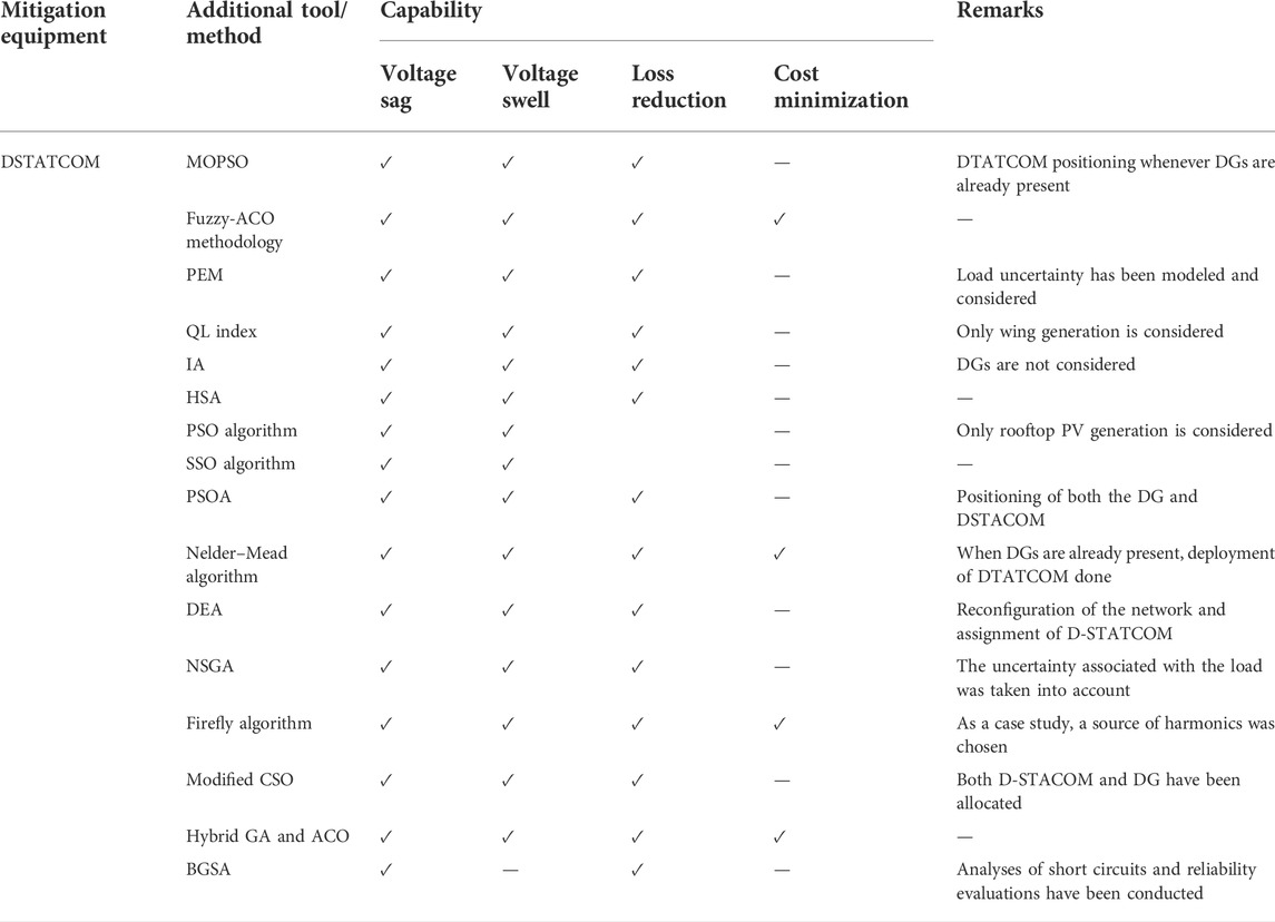
TABLE 2. Overall comparison of various DSTATCOM.
2.2.2 Dynamic Voltage Restorer
DVR is the high-performing and most economical solution to compensate upstream voltage complications in DS. DVR may be taken into consideration as a variable or a controllable voltage source connected in series between PCC and load (Cárdenas et al., 2015). It has energy storage and a series converter. It is connected to the system in series. Whenever the system is subjected to an abnormality or low voltage, the series voltage is injected using a converter. The injected voltage will adjust for the voltage of the system. Consequently, the DVR continually checks the supply line voltage and compares it to the reference AC supply; it then provides the appropriate voltage to correct for voltage variations. It supports to control and maintain a load voltage profile by exchanging reactive power between DVR and DS. Figure 8 gives the power circuit of DVR with energy storage, DC link, converter, filter, injection transformer, bypass, and disconnection equipment as basic elements (Yue et al., 2007). The different topologies of DVR are as follows:
1. Energy storages
A. Without energy storage
a. DVR with no energy storage
B. With energy storage
a. Constant DC link voltage
b. Variable DC link voltage
2. Inverter topology (multilevel inverters)
a. Diode clamped
b. Cascaded H-bridge
c. Flying capacitor
3. 3-Phase inverters
a. Three-phase four-line half bridge
b. Three-phase four -line bridge
c. Three-phase H bridge
d. Three-phase DVR with a split capacitor
e. Three-phase push pull inverter

FIGURE 8. Power circuit of DVR.
2.2.2.1 Survey on dynamic voltage restorer control strategies
Using the cascade H-bridge DVR, Al-Hadidi et al. (2008a) developed a new configuration to mitigate the sever and long duration sagged voltages at customer loads. Moreover, it is suitable for both single- and three-phase sag compensation. Al-Hadidi et al. (2008b) proposed a new technique to alleviate sag by utilizing energy storage capability a cascaded inverter–type DVR. The injected active and reactive power is calculated analytically under different situations of load magnitude and PF. The start/end-point voltage sag and swell in DS can be effectively detected and alleviated in Ali et al. (2018); the authors used RMS detection strategy. Nielsen et al. (2004) presented topologies without DC-link energy storage for three-phase DVRs. The schemes are based upon direct converters so that three independent three-phase to single-phase direct converters are used. In 2016, Messiha, M.A. et al. utilized wavelet transform technique to detect PQD and voltage sag is stabilized effectively (Baraket, 2018). Capacitor-supported interline DVR is addressed in Abdollahzadeh et al. (2014) to mitigate voltage disturbances in DS. In Remya et al. (2018), a PI-based DVR is proposed to mitigate PQ issues successfully in distribution PT DSS power plant. In DVR, with a traditional controller, the application of DVR is limited to low operating level only. To extend application of DVR for varying operating conditions in a higher distribution level artificial intelligence-based controllers such as space vector pulse width modulation (SVPWM), artificial neural network, and fuzzy logic are reported in literature. Generally, ANN has an ability to mimic the decision-making capability of a human or a complex system. The ANN controller-based DVR is reported in Sundarabalan and Selvi (2015), where ANN is capable of constitute the nonlinear correlation among input and output, but the performance depends on a neural network structure and number of training data considered. Unlike ANN, the fuzzy logic controller has definite decision-making based on imprecise or ambiguous data. In Mani and Siddappa Naidu (2015), the authors presented the impact of fuzzy logic controller (FLC) in application of DVR. FLC effectively reduces the transient overshoot of VSI. Ding et al. (2002) utilized a SVPWM-based DVR to mitigate PQ issues under an unbalanced system condition. In addition, it reduces the effect of load voltage negative sequence component on the performance of DVR. In Rini Ann Jerin et al. (2017), a feed-forward vector control algorithm is used to mitigate voltage disturbances. Using this algorithm, DVR generates firing signal for the VSI to inject appropriate compensation voltages. A PV-based DVR is reported in the study by Divyalakshmi and Subramaniam (2017) to mitigate PQ problems. The function of PV is that it not supplies power only to the load but also to the DC-link of DVR. Here, a wavelet transform based controller is employed to transform the PV system role into DVR and to identify PQ event. In 2017, Rini Ann Jerin et al. (2016) introduced a feed-forward and feed-back control of DVR for the improvement of fault ride-through (FRT) capability in the doubly fed induction generator-based wind turbine. In Li et al. (2018), a DVR-based strategy is proposed for the mitigation of voltage sag in DS through DVR for improving power system quality. Table 3 contains the findings of the in-depth investigation on DVRs capabilities.
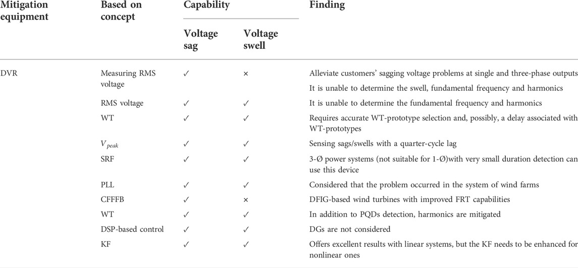
TABLE 3. Overall comparison of various DVRs.
2.2.3 Unified power quality conditioner
Because of nonlinear loads present in power system induces PQ complications, such as harmonics, voltage dips, and spikes in the system. UPQC is employed to enhance the PQ at distribution level. UPQS is a combination of series and shunt active power filter connected back-to-back through a common DC-link capacitor (Fujita and Akagi, 1998). Figure 9 illustrates the basic schematic diagram of UPQC with series and shunt active power filter. It consists of DC link capacitor in between the series and shunt controller. The series controller can be used for series compensation and the shunt controller for current compensation. During compensation, the DC capacitor rating for both controllers should be the same. The shunt active filter improves PF, mitigates harmonics in load current and load unbalance whereas the series active filter can alleviate supply side disturbances such as harmonics, voltage dips/spikes, flicker, and voltage unbalance in a network-like distribution (Faranda and Valadè, 2002). The topologies of UPQC are as follows:
1. Converter topology
a. Current source topology
b. Voltage source topology
2. Three-phase four-wire system
c. Three-phase four-wire four-leg topology
d. Three-phase four-wire neutral clamped topology
e. Three-phase four-wire capacitor-connected shunt VSI
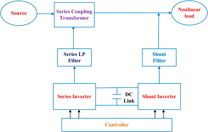
FIGURE 9. Basic schematic diagram of UPQC with series and shunt active power filter.
2.2.3.1 Survey on unified power quality conditioner control strategies
For the very first time, Fujita and Akagi (1998) suggested a back-to-back topology of series and shunt APFs that could compensate for voltage flicker/imbalance, reactive power, negative-sequence current, and harmonics; tested it with an experimental setup; and titled it “unified power quality conditioner” (UPQC). Similar to the unified power flow controller (UPFC) used in the transmission system, UPQC is employed in the distribution system (Faranda and Valadè, 2002). Based on topology, in Hingorani (2007) UPQC are classified into two types: 1) voltage source inverter (VSI)-based UPQC and 2) current source inverter (CSI)-based UPQC. The switching action is accomplished by the use of a pulse width modulation (PWM) technology (Fabula et al., 2021). In CSI-based UPQC the voltage blocking diode is connected in series with IGBT. Comparing these two configurations shows how VSI benefits our operation. The VSI design is capable of multilevel processing, but is also less expensive than the CSI design (Graovac et al., 2000). The classification of UPQC is further subdivided into single-phase and three-phase supply systems, depending on the supply system. Additionally, single-phase and three-phase systems can be classified as single-phase two-wire, three-phase three wire, or three-phase four wire. For single-phase and three-phase systems, voltage sag and swell concerns are common, however voltage unbalancing in three-phase systems is beneficial. Current harmonics and load reactive current are serious issues in a single-phase system (Corrêa et al., 2003). Also, with a three-phase four wire design, an additional, unbiased current compensation ring is required. In Chakraborty et al. (2007) utilized p-q theory-based active filtering named universal active power line conditioner (Aredes et al., 1998) and unified PQ conditioner to solve power flow and PQ issues, respectively. Further Distributed intelligent energy management system (DIEMS) is used to optimize operating cost. Without proper forecasting, DIEMS cannot function. Fuzzy ARTMAP neural networks are utilized to anticipate daily schedules. A novel optimization approach is developed, using linear programming and heuristics. On the basis of peer-reviewed publications. Table 4 summarizes the various kinds of UPQCs and their associated applications. For PQDs such as voltage drop, swell, imbalance, and harmonics and for load current problems such as unbalance, neutral current, and reactive current, the literature shows that UPQC is effective.
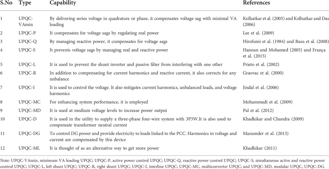
TABLE 4. Overall comparison of various UPQCs.
2.2.4 Uninterruptable power supply
When the utility mains are unavailable, an uninterruptible power supply (UPS) system provides safe, conditioned, and uninterruptible power to critical loads such as data centers, airline computers, medical support systems in hospitals, communication networks, and many others. The offline UPS consists of a rectifier, DC filter, battery bank, an inverter, an AC filter, and a static bypass switch, as depicted in Figure 10. Generally, it is installed between commercial utility mains and critical loads. When there is a power outage or other abnormality, the UPS effectively switches from mains power to its own power source almost instantaneously (Guerrero et al., 2007). The output of the UPS system should usually be controlled sinusoidally with a low THD regardless of changes in the connected system voltage and load. UPS systems can be broadly classified into two types: static UPS systems and rotary UPS systems. Static UPS systems are suitable for small loads and rely on power electronics converters and inverters to process, store, and deliver power in the event of grid failure, whereas rotary UPS systems are suitable for large loads and rely on motors and generators (Blondel and Monney, 2009; Lu et al., 2019).
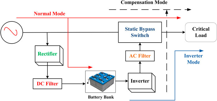
FIGURE 10. Basic block diagram of off-line UPS.
2.2.4.1 Survey on uninterruptable power supply
According to UPS operation and configuration, UPS systems are classified into three types. Online, offline, and line-interactive are the three categories (Karve, 2000). However, among these topologies, the line-interactive UPS system (Bukhari et al., 2013) has always been preferred by industrial consumers due to its high efficiency and power-compensating capabilities in comparison to the offline and online UPS topologies (Bukhari et al., 2017). It is further subdivided into two distinct topologies for the line-interactive UPS system. The first topology connects the inductors in parallel with the critical load and utility grid. In another topology, a bilateral converter is connected parallel to the utility and operates differently during regular and irregular power obligations. When connected to a regular power source, it acts as a battery charger (Kawabata et al., 1989; Yeh and Manjrekar, 2007). However, when abnormalities occur, it acts as an inverter, providing backup power to the load. The primary objective of this topology is to suppress the harmonics of the input current (Jou and Wu, 1995). However, a negligible amount of reactive power compensation will be required (Nakata, 2019; Zhao et al., 2019). The addition of a triport transformer between the load and utility for isolation increases the size of the system. In Sivamani et al. (2021), a novel improved single-phase line-interactive UPS has been proposed for low-power applications. When input power is present, the UPS functions as an output voltage regulator, an active power filter, and a battery charger. In the event of a power failure at the input, the UPS supplies a regulated sinusoidal voltage to the load, drawing energy from the battery. In another research study, Kwon et al. (2001) propose a transformer-less line-interactive uninterruptible power supply (UPS) with low ground leakage current. A high-efficiency bidirectional inverter with low ground leakage current is suggested for performing line-interactive UPS functions. The parasitic capacitance between the inverter and the AC voltage ground is clamped to zero voltage during a positive line cycle and to the AC voltage during a negative line cycle as the inverter operates. Using a mix of supercapacitors and liquid nitrogen (LN2), the first uninterruptible power supply (UPS) was presented in Choi and Yang (2018), which can replace traditional UPS systems such as fuel-burning engines or batteries with this highly viable option.
2.3 Review on controllers used in CPDs
The widely used controller in CPDs are as follows:
A. PI controller
B. Phase shift control
C. Hysteresis controller
D. Sliding mode controller
E. One cycle control
2.3.1 PI controller
Commonly, the PI controller is utilized to provide a regulated gating signal for the voltage source converters functioning. The PI controller compares the observed bus voltage to the reference voltage and then creates an error signal. Figure 11A shows the schematic representation of PI controller.
where
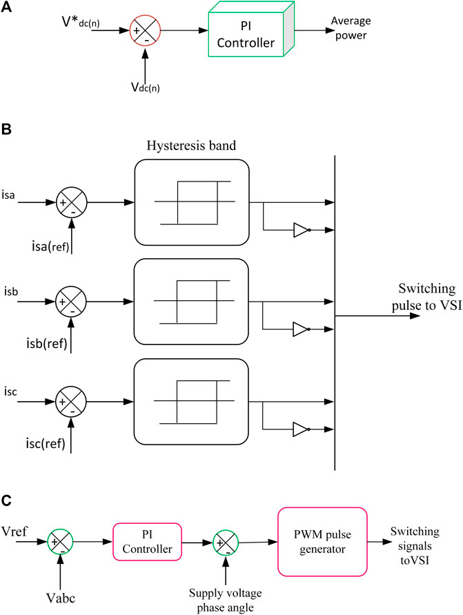
FIGURE 11. (A) Schematic diagram of PT controller. (B) Schematic diagram of Hysteresis controller. (C) Block diagram of phase shift control.
The subscripts n and n-1 denote past and current states, respectively. Also, a and b represent the proportional and integral gains of the PI controller, respectively. c is the magnitude of the reference supply current, I. From the source reference current, the remaining three-phase reference currents are derived. After producing the reference current, the PI controller produces the precise switching signals needed for the functioning of the six VSC switches (Patel and Sahu, 2016).
2.3.2 Hysteresis control
The primary function of the control scheme is to produce gating signals for the inverter with minimal current error. Identifying the difference between the actual and source currents, the controller provides the error signal. The erroneous signal is then compared to the hysteresis band, which typically yields 1%–5% of the current value. The following is the logic employed by the hysteresis controller (Latran et al., 2015).
IF
Here,
2.3.3 Phase shift controller
Utilizing a phase shift control approach, DSTATCOM’s voltage regulation is attained. In this method, as seen in Figure 11C, the RMS voltage of the load is measured and compared to the reference voltage, and an error signal is produced (Masand et al., 2006). The error signal is then sent to the PI controller as an input. The output angle of the PI controller corresponds to the angle between the VSC output voltage and the AC supply terminal voltage. The signal necessary to activate the PWM generator is then produced by adding the output of the PI controller to the phase angle of the balanced supply voltages. The primary benefit of this technology is its practical applicability. However, it cannot perform harmonic reduction for nonlinear loads (Kumar et al., 2013).
2.3.4 Sliding mode controller
This approach applies a discrete input signal to a system whose outcome is not proportional to the change in input. The signal modifies the system’s dynamics and causes it to slide along the cross section of its typical performance. The controller’s model is based on the state variable values X1, X2, which are described as (Singh et al., 2008):
where
Here, Z is the switching plane function, and its expression is as follows:
Using the following equation, we get the value of the reference supply current
The values of three-phase reference current are derived from the supply of reference current. The information is then provided as input to the controller, which generates gate pulses for the instrument. The optimal performance is achieved by fine-tuning the gain constants C1, C2, C3, and C4.
2.3.5 One cycle control
In this strategy, there is no need to determine the reference voltages or currents. This will have two circuits, a three-phase bridge and an N-half-phase bridge. The benefit of the neutral line compensation bridge is that it eliminates the harmonic current existing in the line at different frequencies (Jayachandran and Murali Sachithanandam, 2016). The control circuit comprises the OCC core, the current selection, the feedback circuit, the integrator, and reset. This control circuit will aid the operation of the vector.
3 PQ standards
The problems associated with PQ necessitate the creation of appropriate standards. Standards are primarily designed to improve the reliability, safety, and efficiency of products. In order to better study for and respond to future challenges, researchers and organizations such as the Electric Power Research Institute (EPRI), the IEEE 1159 working group, the Pennsylvania–New Jersey–Maryland (PJM) area, and the California Public Utility Commission (CPUC) have been collaborating. Table 5 depicts the fundamental underlying principles of the various power quality standards. The important IEEE and IEC PQ standards are discussed in the following subsections.
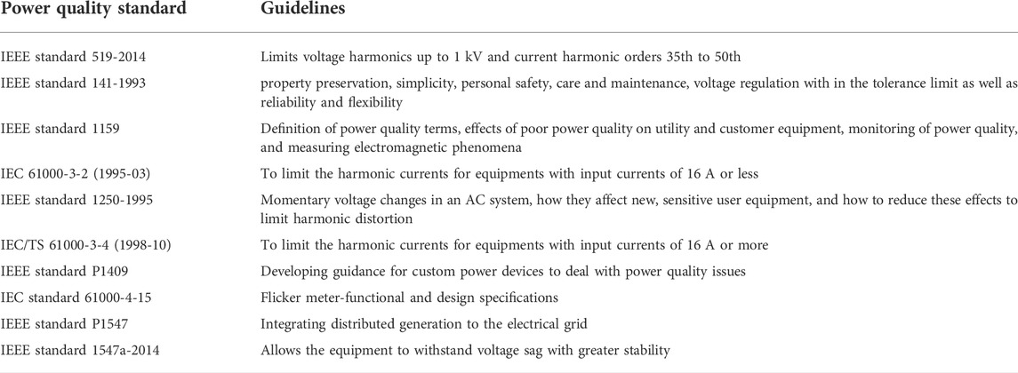
TABLE 5. Important power-quality standards and their guidelines.
3.1 IEEE standard 519-2014
The IEEE standard 519-2014 is the revision of IEEE std 519-1992, which specifies voltage harmonics limits up to 1 kV and current harmonic orders 35th to 50th, and was recently issued. In addition, two new measurement methods have been introduced: very short-time measurements for 1 day with a time interval of 3 s and short-time measurements for 1 week with a time interval of 10 min. IEEE 519 discusses allowable nonfundamental frequency waveform distortion when it connects from the source to the load at a location known as the “point of common coupling (PCC).” As specified in IEEE 519-2014, the limits specified in this standard are applicable only for steady-state operation at PCC. These limits may be exceeded during transient conditions (Committee et al., 2014).
3.2 IEEE standard 141-1993
IEEE standard 141-1993 (Recommended practice for industrial plant electric power distribution) is a revision of ANSI/IEEE standard 141-1986, and this guide provides an in-depth analysis of fundamental electrical power system considerations. This standard establishes guidelines for property preservation, simplicity, personal safety, care and maintenance, as well as reliability and flexibility. Furthermore, IEEE std 141 specifies voltage regulation within the tolerance limit under all load conditions (IEEE std 141, 1993).
3.3 IEEE standard 1159
IEEE standard 1159 (Recommended practice for monitoring electric power quality) describes how to monitor the PQ of AC systems. Monitoring of PQ can be improved by interpreting results obtained from appropriate monitoring locations and systematic studies. To obtain useful and accurate voltage and current data, it is necessary to use proper and safe measurement techniques. This standard specifies methods for measuring electromagnetic phenomena and the impact of poor PQ on utility and customer equipment. Figure 2 illustrates the IEEE 1159 classification of PQ issues. This recommended practice defines nominal conditions and deviations from these nominal conditions that may originate in the source of supply or load equipment or from interaction between source and load (IEEE Std, 1995).
3.4 IEC 61000-3-2 (1995-03)
It provides current harmonic limitations for felicitous electrical and electronic devices with an input phase current of less than or equal to 16 A and is intended for connection to a low voltage DS. Type tests are used to ensure compliance with this standard. Bounds have not yet been considered for systems with a line to neutral voltage of less than 220 V.
3.5 IEEE standard 1250
IEEE standard 1250 (guide for service to equipment susceptible to momentary voltage disturbances) is a technical guide for momentary voltage disturbances in AC distribution and utilization systems. Computers and other electronic devices that use solid state electric power conversion are not resistant to abnormal conditions, such as faults and surges. Also, this equipment is more vulnerable to temporary voltage disturbances. This standard establishes upper and lower bounds on the effect of harmonic distortion. Additionally, IEEE 1250 specifies procedures for mitigating these effects (IEEE std 1250, 2011).
3.6 IEC/TS 61000-3-4 (1998-10)
IEC/TS 61000-3-4 specifies harmonic current emission limits for low-voltage power distribution equipment rated over 16 amps. Equipment with a rated input current more than 16 A per phase, intended to be connected to one of the following public low-voltage alternating current distribution systems: 240 V single phase, two or three wires; 600 V three phase, three or four wires. To establish whether or not equipment is suitable for connection, the guidelines define the information a supplier authority must offer.
3.7 IEEE standard P1409
Custom power devices are advantageous for mitigating voltage drops and outages. IEEE standard P1409 is a technical guide that provides guidance and performance expectations for the use of CPDs in electricity companies’ DSs to improve power quality. It provides comprehensive information on CPDs as a possible solution to PQ problems.
3.8 IEC standard 61000-4-15
IEC standard 61000-4-15 describe functional and layout specifications for flicker measuring equipments supposed to signify the precise perception level of flicker for all realistic voltage fluctuation waveforms. The output of flicker-meters functioning in accordance with this standard is being used to determine the degree of flicker (International Standard International Standard, 2003).
3.9 IEEE standard P1547
This standard specifies criteria and requirements for interconnecting DG with the electric power system (EPS). IEEE P1547 specifies performance, testing, operating, safety, and maintenance criteria for interconnections.
3.10 IEEE standard 1547a
IEEE standard 1547a-2014 address new guidelines related to voltage dip. It consists of new settings that would typically permit the equipment to tolerate the voltage dip with increased stability (IEEE Std, 1995).
4 Proposed power quality mitigation technique
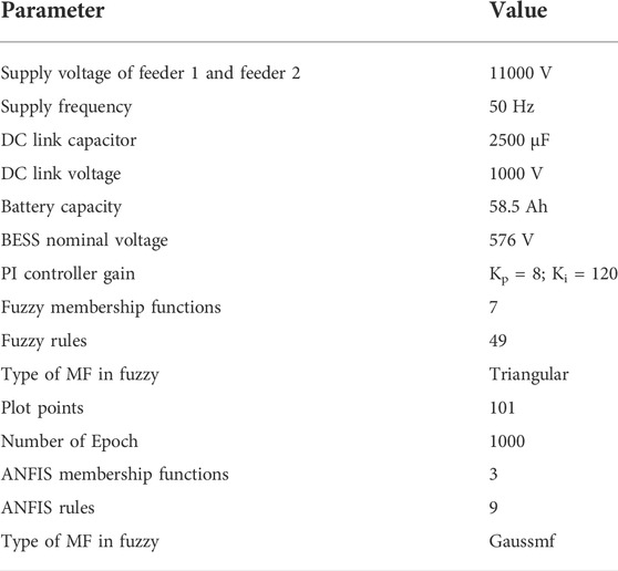
Detailed review on PQ mitigation techniques shows that the UPQC connected between the multiple feeders gives better performance. Commonly used PQ mitigation techniques with its capabilities are compared shown in Table 6. Moreover, control scheme is responsible for increasing the performance. Using nonlinear loads and integrating RES into the grid causes power quality disturbances (PQDs). This section describes using an adaptive neuro-fuzzy inference system (ANFIS) in an MF-IUPQC to address PQDs such voltage/current fluctuations and harmonic distortions. MF-IUPQC has four diode-clamped inverters on three legs. Switching is accomplished through the use of space vector pulse width/duration modulation (SVPWM). MATLAB/Simulink is utilized to implement the proposed control method. The effectiveness of the developed ANFIS controller is evaluated by comparison with the fuzzy logic (FL) and standard proportional-integral (PI) controllers. As demonstrates in Figure 12, the MF-IUPQC is formed by connecting two series VSCs and two shunt VSCs back-to-back via a common DC-link capacitor. Here, each VSC is separately controlled. Controllability and the generation of reference currents are the two primary considerations when operating the MF-IUPQC system. The most frequently utilized control schemes in MF-IUPQC system control are synchronous reference frame (SRF) and PQ-theory.
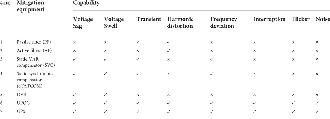
TABLE 6. Comparison of all PQ mitigation techniques with its capabilities.

FIGURE 12. Schematic diagram of MF-IUPQC.
The following are the major intuitions of this manuscript:
1. Based on ANFIs MF-IUPQC was developed in this article.
2. Enhances dynamic performance and provides smooth DC-link voltage.
3. THD is reduced below the IEEE 519-1992 permissible limit of 5%.
4.1 Control strategy
This design utilizes two VSC controls. Shunt voltage source converters (VSCs) regulate capacitor voltage and compensate for reactive and harmonic loads. Series VSCs minimize sag/swell, harmonics, and interruptions.
4.1.1 Series compensation control
The SRF theory is used to control series VSC for each feeder, as illustrated in Figure 13A. Here, a three-phase source voltage is transformed to a rotating reference frame using Park’s transformation. This is described in Eq. 7.
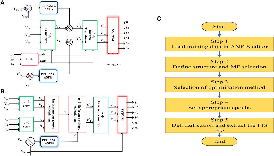
FIGURE 13. (A) Schematic diagram of series control. (B) Schematic diagram of shunt control. (C) Flowchart for training ANFIS.
The d-q frame reference voltage values are re-transformed into the
The switching pulses are obtained by comparing the reference (
4.1.2 Shunt compensation control
The PQ-theory is used to control shunt VSC for each feeder, as illustrated in Figure 13B. Here, the three-phase load voltages and currents are transformed to ά–β coordinates. This is depicted in Eqs 10, 11.
The instantaneous real and reactive components could be estimated using the above equations.
4.2 ANFIS controller
ANFIS is a hybrid system that combines neural networks (NNs) and fuzzy inference techniques. Thus, it takes advantage of the fuzzy system’s ability to make inferences and the ability of neural networks to learn (Pavan Kumar and Kartheek, 2016). The ANFIS requires a collection of input–output data and maps the input data to the output using a set of membership functions (MFs). Ideally, the chosen MF should have as small an error as possible when comparing the actual output to the ANFIS-sketched results. To train the NN, we use a combination of the Gaussian MF and fuzzy input. The fuzzy inference system (FIS) is linked to a rule base in the NN block. The simulation parameters are shown below.
The FIS is being trained by BPA. The BP algorithm is utilized to train FFNN. Mamdani and Sugeno are the two most popular FIS (Kisi, 2013). Takagi Sugeno FIS is implemented in this case using ANFIS. Details of ANFIS training flowchart are depicted in Figure 13C.
4.2.1 Simulation results and discussion
The performance of the MF-IUPQC is examined under voltage swell, sag, and harmonic conditions using ANFIS controlled MF-IUPQC. A nonlinear load is created by diode bridge rectifier; Third- and fifth-order harmonics are created deliberately in the two feeders; a voltage sag of 20% and a swell of 20% is introduced using a programmable voltage source.
Case 1:. Performance of the system under voltage sag and swell conditions.Voltage sag and swell are applied to the MF-IUPQC system over periods of 0.1–0.2 s and 0.3s–0.4 s, respectively. In Figure 14 the source voltages, injected voltages, and currents of both feeders using ANFIS controllers are presented.From the waveforms, during voltage sag, the system voltage reduces by 0.2 p.u. magnitude while voltage swell increases it by 0.2 p.u. magnitude. Simultaneously, current increases in magnitude during the voltage sag period and falls in magnitude during the voltage swell period. To compensate for these effects, the series VSCs inject the compensating voltage and the shunt VSCs inject compensation current into the system. In other words, during low voltage, the reactive power from the DC-link capacitor is injected into the system.From the DC link capacitor voltage waveform, demonstrating the system excellent dynamic response. A comparative analysis of response variables such as 1) rise time, 2) slew rate, 3) overshoot 4) settling time, 5) RMS voltage, 6) peak value, and 7) peak time values was conducted and is presented in Table 7.
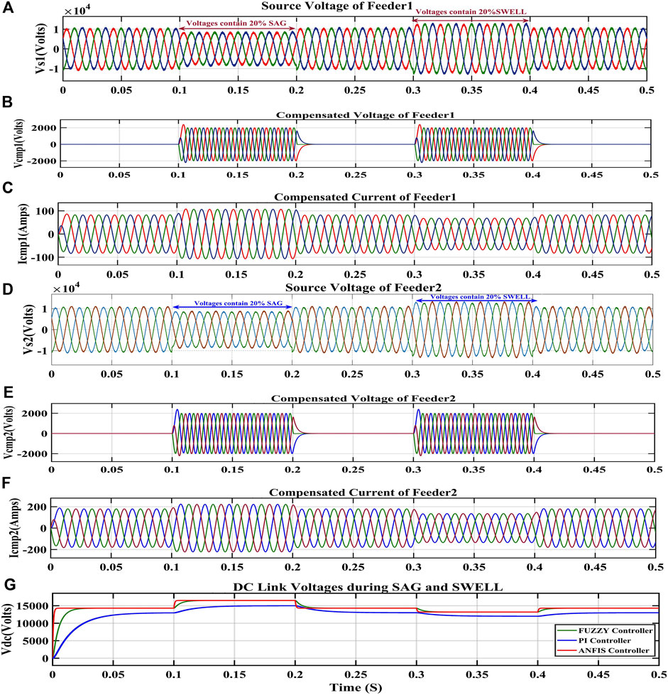
FIGURE 14. Waveforms of feeder 1 and feeder 2 under sag and swell.
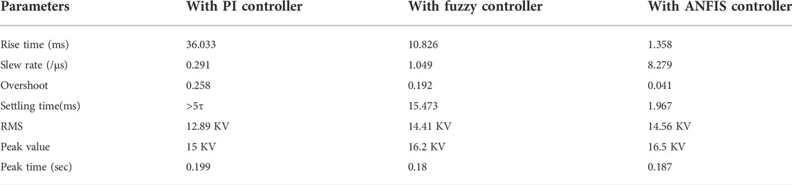
TABLE 7. DC Link voltage comparison of MF-IUPQC with different controllers.
Case 2:. Performance of the system under current harmonics conditions.A nonlinear load is created by diode bridge rectifier. In order to introduce nonlinearities into the load, the diode bridge rectifier supplies the resistive loads of 100 Ω and 200 ohms on feeders 1 and 2, respectively. The load, compensated, and source current waveforms of both feeders with ANFIS controllers are shown in Figure 15.The load current of feeder 1 and feeder 2 is distorted (not pure sinusoidal) due to the presence of nonfundamental harmonics in the system. During current harmonics in the system, the shunt VSCs of IUPQC inject the compensating current into the system and the current harmonics get mitigated so that the waveform of the source current of both feeders is almost sinusoidal in nature.The load current waveform contains harmonics due to the nonlinear load, whereas the source current is sinusoidal, resulting in a decrease in THD from load to source are tabulated in Table 8. From load current to source current the THD of first feeder is reduced from 8.46 to 1.32 percent and that of second feeder reduced from 7.69 to 1.56 percent. The DC link voltage demonstrates that the ANFIS controller performs well with current harmonics in the system.
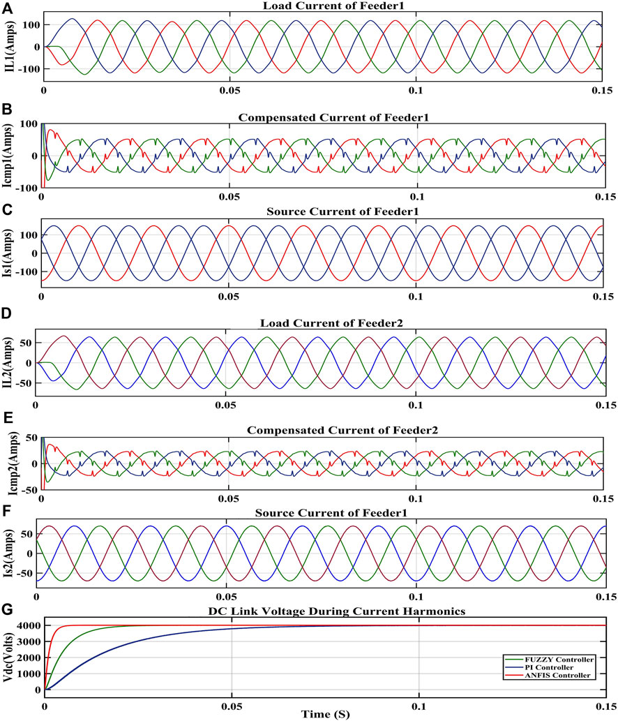
FIGURE 15. Waveforms of feeder 1 and feeder 2 under current harmonics.

TABLE 8. THD during current harmonics.
Case 3:. Performance of the system under voltage harmonics conditions.In order to take into account, the voltage irregularities, harmonics of the third and fifth orders are purposefully generated inside the two feeds. To supply the loads, starting at t = 0.05 s, the first feeder voltage is considered to have 15 percent third and 20 percent fifth-order harmonics, and the second feeder voltage is considered to have 15 percent third and 15 percent fifth-order harmonics.The source, compensated, and load voltage waveforms of both feeders with ANFIS controllers are shown in Figure 16. The source voltage waveform of feeder 1 and feeder 2 contains harmonics, whereas the load voltage is sinusoidal due to compensation voltage by the series VSCs of IUPQC, resulting in a decrease in THD from source to load. These results are tabulated in Table 9.Compensated voltages are applied to the load side of both feeders in order to correct distorted voltages on the source side. The total harmonic distortion (THD) of Feeder 1 has decreased to 2.73 percent from 30.35 percent while the THD of Feeder 2 has decreased from 28.14 percent to 2.08 percent. The DC link voltage waveform demonstrates that the ANFIS controller performs well with voltage harmonics in the system.
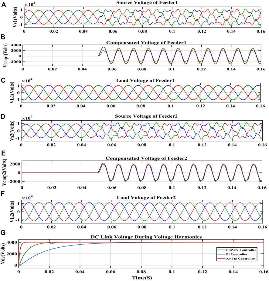
FIGURE 16. Waveforms of feeder 1 and feeder 2 under voltage harmonics.
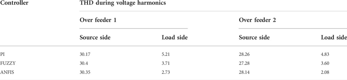
TABLE 9. THD during voltage harmonics.
5 Overall review of PQ mitigation techniques
Reviewing the literature, we can come to the following inferences and make recommendations for further studies:
➢ From PQ analysis tools we found that Fast Fourier transform (FFT), singular value decomposition (SVD), and artificial neural network (ANN) are mostly used to analyze harmonics.
➢ In PQ monitoring system, current transformers (CTs), potential transformers (PTs), and transducers (XD) are used as sensors for collecting data and analyzed the data using data visualization methods in the form of graphs. They can help in predicting the power quality. Artificial intelligence (AI) techniques are seldom used by researchers; they are the future solutions to analyzing and predicting more accurately.
➢ It can be observed that efforts to D-STATCOM placement and sizing optimization have made little growth over the last decade. It can also be inferred that most studies employed a single D-STATCOM to minimize power loss and did not investigate multiple D-STATCOMs in radial distribution networks. It is also determined that efficient D-STATCOM allocation for unbalanced distribution networks has not been done, and further research is suggested.
➢ By incorporating improved power converters into DVR, we may enhance its performance in terms of cost, efficiency, reliability, simultaneous compensation of deep/long voltage sags/swells, and harmonics. The main focus has been on DVR and distributed generation integration. Future work should consider DVR, smart grids, and microgrids.
➢ This study briefly discusses the various configurations of UPQC. The UPQC scheme may be advantageous for concurrently resolving current and voltage-related power-quality issues.
➢ More changes will be made to power converters to increase power quality. Improved control strategies will be one among the enhancements. Using these control systems will allow for the production of more power with higher quality.
➢ Advanced microcontrollers and faster switching devices have led to more powerful, efficient, and affordable UPS systems with and without transformers. New approaches are being developed to assure fast transient and dynamic response, reduced THD, effective voltage regulation, and load stability.
➢ If UPS technology improves, then fuel cells may replace batteries, and low-power applications will be beneficial. Fuel cells and supercapacitor UPS systems have not been much researched. Taking into account the pros of the hybrid system, we can expect an UPS system that is more advanced, has more features, and works better.
6 Conclusion
In this study, an attempt has been made to discuss a variety of PQ disturbances (PQDs) in AC and DC systems, PQ monitoring techniques, fundamental standards, and PQ mitigation approaches. Custom power devices such as DSTATCOM, DVR, UPQC, and UPS are the most recent evolution of interface devices designed to mitigate voltage/current disruptions and improve power quality by compensating for reactive and harmonic power generated or absorbed by the load. Finally, the use of an ANFIS in MF-IUPQC to address PQDs such as voltage/current fluctuations and harmonic distortions is described. To improve MF-IUPQC system performance, ANFIS was implemented and compared against PI and fuzzy. The presented system improves load voltage regulation and provides smooth DC-link voltage and harmonics compensation. The proposed systems’ THD values for both the feeders are low when compared to those of competing controllers. The investigation found that the suggested MF-IUPQC system with ANFIS has better voltage profiles and harmonic reduction abilities.
Author contributions
Conceptualization, writing—original draft preparation, and editing: TR; conceptualization, review, editing, and supervision: KS. All authors have read and agreed to the published version of the manuscript.
Acknowledgments
The authors are thankful to the management of Vellore Institute of Technology, VIT-Vellore. Also, this work is carried out in the Digital Simulation Lab (DSL) from the school of electrical engineering (SELECT), VIT-Vellore, Tamil Nadu, India.
Conflict of interest
The authors declare that the research was conducted in the absence of any commercial or financial relationships that could be construed as a potential conflict of interest.
The reviewer PK declared a shared affiliation with the authors at the time of the review.
Publisher’s note
All claims expressed in this article are solely those of the authors and do not necessarily represent those of their affiliated organizations, or those of the publisher, the editors, and the reviewers. Any product that may be evaluated in this article, or claim that may be made by its manufacturer, is not guaranteed or endorsed by the publisher.
References
Aamir, M., Ahmed Kalwar, K., and Mekhilef, S. (2016). Review: Uninterruptible power supply (UPS) system. Renew. Sustain. Energy Rev. 58, 1395–1410. doi:10.1016/j.rser.2015.12.335
Abbasi, A. R., Khoramini, R., Dehghan, B., Abbasi, M., and Karimi, E. (2015). A new intelligent method for optimal allocation of D-STATCOM with uncertainty. J. Intell. Fuzzy Syst. 29, 1881–1888. doi:10.3233/IFS-151666
Abdollahzadeh, H., Jazaeri, M., and Tavighi, A. (2014). A new fast-converged estimation approach for Dynamic Voltage Restorer (DVR) to compensate voltage sags in waveform distortion conditions. Int. J. Electr. Power & Energy Syst. 54, 598–609. doi:10.1016/j.ijepes.2013.08.012
Agarwal, R. K., Hussain, I., and Singh, B. (2017). Implementation of LLMF control algorithm for three-phase grid-tied SPV-DSTATCOM system. IEEE Trans. Ind. Electron. 64, 7414–7424. doi:10.1109/TIE.2016.2630659
Akbari-Zadeh, M. R., Kokabi, R., and Gerami, S. (2014). Dstatcom allocation in the distribution system considering load uncertainty. J. Intell. Fuzzy Syst. 27, 691–700. doi:10.3233/IFS-131027
Al-Hadidi, H. K., Gole, A. M., and Jacobson, D. A. (2008a). A novel configuration for a cascade inverter-based dynamic voltage restorer with reduced energy storage requirements. IEEE Trans. Power Deliv. 23, 881–888. doi:10.1109/TPWRD.2007.915989
Al-Hadidi, H. K., Gole, A. M., and Jacobson, D. A. (2008b). Minimum power operation of cascade inverter-based dynamic voltage restorer. IEEE Trans. Power Deliv. 23, 889–898. doi:10.1109/TPWRD.2007.915996
Al-Nimma, D. A., Al-Hafid, M. S. M., and Mohamed, S. E. (2011). “Voltage profile improvements of Mosul city ring system by STATCOM reactive power control,” in Int. Aegean Conf. Electr. Mach. Power Electron. ACEMP 2011 Electromotion 2011 Jt. Conf., 525–530. doi:10.1109/ACEMP.2011.6490654
Ali, K. K., Talei, M., Siadatan, A., and Rad, S. M. H. (2018). “Power quality improvement using novel dynamic voltage restorer based on power electronic transformer,” in 2017 IEEE Electr. Power Energy Conf, EPEC 2017 2017-Octob, 1–6. doi:10.1109/EPEC.2017.8286166
Aredes, M., Heumann, K., and Watanabe, E. H. (1998). An universal active power line conditioner. IEEE Trans. Power Deliv. 13, 545–551. doi:10.1109/61.660927
Asakimori, K., Murai, K., Tanaka, T., and Babasaki, T. (2014). “Effect of inrush current flowing into EMI filter on the operation of ICT equipment in HVDC system,” in INTELEC, Int. Telecommun. Energy Conf, 2014-Janua. doi:10.1109/intlec.2014.6972194
Bagheri Tolabi, H., Ali, M. H., and Rizwan, M. (2015). Simultaneous reconfiguration, optimal placement of DSTATCOM, and photovoltaic array in a distribution system based on fuzzy-aco approach. IEEE Trans. Sustain. Energy 6, 210–218. doi:10.1109/TSTE.2014.2364230
Bagherinasab, A., Zadehbagheri, M., Abdul Khalid, S., Gandomkar, M., and Ahmad Azli, N. (2013). Optimal placement of D-STATCOM using hybrid genetic and ant colony algorithm to losses reduction. Int. J. Appl. Power Eng. 2. doi:10.11591/ijape.v2i2.2408
Baraket, C. F. (2018). Voltage Sag S Mit tigation n Emplo oying Dynamic c Voltag ge Res torer with w Min nimum Energy y Requi irement ts. Anal lysis mplemen ntation Im 1, 1–6.
Bhadane, K. V., Ballal, M. S., and Moharil, R. M. (2012). Investigation for causes of poor power quality in grid connected wind energy - a review. Asia-Pacific Power Energy Eng. Conf. APPEEC. doi:10.1109/APPEEC.2012.6307152
Bierhoff, M. H., and Fuchs, F. W. (2008). DC-link harmonics of three-phase voltage-source converters influenced by the pulsewidth-modulation strategy - an analysis. IEEE Trans. Ind. Electron. 55, 2085–2092. doi:10.1109/TIE.2008.921203
Blondel, E., and Monney, C. (2009). “Efficient powering of communication and IT equipments using rotating UPS,” in TELESCON 2009 - 4th Int. Telecommun. Energy Spec. Conf. Power Supply Qual. Effic.
Bukhari, S. S. H., Lipo, T. A., and Kwon, B. Il (2013). An inrush current reduction technique for the line-interactive uninterruptible power supply systems. IECON Proc. Ind. Electron. Conf., 430–434. doi:10.1109/IECON.2013.6699174
Bukhari, S. S. H., Lipo, T. A., and Kwon, B. Il (2017). An online UPS system that eliminates the inrush current phenomenon while feeding multiple load transformers. IEEE Trans. Ind. Appl. 53, 1149–1156. doi:10.1109/TIA.2016.2622229
Cárdenas, V., González-Garciýa, M. A., and Álvarez-Salas, R. (2015). A dynamic voltage restorer with the functions of voltage restoration, regulation using reactive power, and active filtering. Electr. Power Components Syst. 43, 1596–1609. doi:10.1080/15325008.2015.1050612
Chabok, B. S., and Ashouri, A. (2016). Optimal placement of D-STATCOMs into the radial distribution networks in the presence of distributed generations. Am. J. Electr. Electron. Eng. 4, 40–48. doi:10.12691/ajeee-4-2-1
Chakraborty, S., Weiss, M. D., and Simões, M. G. (2007). Distributed intelligent energy management system for a single-phase high-frequency AC microgrid. IEEE Trans. Ind. Electron. 54, 97–109. doi:10.1109/TIE.2006.888766
Chen, C. S., Lin, C. H., Hsieh, W. L., Hsu, C. T., and Ku, T. T. (2013). Enhancement of PV penetration with DSTATCOM in taipower distribution system. IEEE Trans. Power Syst. 28, 1560–1567. doi:10.1109/TPWRS.2012.2226063
Choi, W. Y., and Yang, M. K. (2018). Transformerless line-interactive UPS with low ground leakage current. IEEE Trans. Ind. Electron. 65, 9468–9477. doi:10.1109/TIE.2018.2815948
Committee, D., Power, I., and Society, E. (2014). in IEEE 519 Recommended Practice and Requirements for Harmonic Control in Electric Power Systems IEEE Power and Energy Society (IEEE).29
Cookson, M. D., and Stirk, P. M. R. (2019). Network time Protocol version 4: Protocol and algorithms specification. Internet Eng. Task Force 1–110.
Corrêa, J. M., Chakraborty, S., Simões, M. G., and Farret, F. A. (2003). A single phase high frequency AC microgrid with an unified power quality conditioner. Conf. Rec. - IAS Annu. Meet. (IEEE Ind. Appl. Soc. 2, 956–962. doi:10.1109/ias.2003.1257652
Dash, P. K., Swain, D., Liew, A., and Rahman, S. (1996). An adaptive linear combiner for on-line tracking of power system harmonics. IEEE Trans. Power Syst. 11, 1730–1735. doi:10.1109/59.544635
De Carne, G., Buticchi, G., Zou, Z., and Liserre, (2018). Reverse Power Flow Control in a ST-Fed Distribution Grid. IEEE Trans. Smart Grid 9 (4), 3811–3819.
Ding, H., Shuangyan, S., Xianzhong, D., and Jun, G. (2002). A novel dynamic voltage restorer and its unbalanced control strategy based on space vector PWM. Int. J. Electr. Power & Energy Syst. 24, 693–699. doi:10.1016/S0142-0615(02)00004-2
Divyalakshmi, D., and Subramaniam, N. P. (2017). Photovoltaic based DVR with power quality detection using wavelet transform. Energy Procedia 117, 458–465. doi:10.1016/j.egypro.2017.05.171
Dugan, R., McGranaghan, and M., Santoso, S., and Beaty, H. (2017). Electrical power systems quality. Second Edition. doi:10.1007/978-3-319-51118-4_1
Edris, A. A., Adapa, R., Baker, M. H., Bohmann, L., Clark, K., Habashi, K., et al. (1997). Proposed terms and definitions for flexible AC transmission system (FACTS). IEEE Trans. Power Deliv. 12, 1848–1853. doi:10.1109/61.634216
El-Habrouk, M., Darwish, M. K., and Mehta, P. (2000). Active power filters: A review. IEE Proc. Electr. Power Appl. 147, 403–413. doi:10.1049/ip-epa:20000522
Fabula, J., Sharda, A., Luck, J. D., and Brokesh, E. (2021). Nozzle pressure uniformity and expected droplet size of a pulse width modulation (PWM) spray technology. Comput. Electron. Agric. 190, 106388. doi:10.1016/j.compag.2021.106388
Faranda, R., and Valadè, I. (2002). UPQC compensation strategy and design aimed at reducing losses. IEEE Int. Symp. Ind. Electron. 4, 1264–1270. doi:10.1109/isie.2002.1025971
Fujita, H., and Akagi, H. (1998). The unified power quality conditioner: The integration of series- and shunt-active filters. IEEE Trans. Power Electron. 13, 315–322. doi:10.1109/63.662847
Giancaterino, J. A. (1994). Dc-dc converter plants and their ability to clear distribution fuses. IEEE 4, 315–320.
Graovac, D., Vladimir, K., and Alfred, R. (2000). “Power quality compensation using universal power quality conditioning system.” IEEE Power Engineering Review 20 12, 58–60.
Guerrero, J. M., de Vicuña, L. G., and Uceda, J. (2007). Uninterruptible power supply systems provide protection. EEE. Ind. Electron. Mag. 1, 28–38. doi:10.1109/MIE.2007.357184
Gupta, N., Seethalekshmi, K., and Shukla, S. (2021). Engineering science and technology , an international journal wavelet based real-time monitoring of electrical signals in distributed generation ( DG ) integrated system. Eng. Sci. Technol. Int. J. 24, 218–228. doi:10.1016/j.jestch.2020.07.010
He, J., and Li, Y. W. (2011). Analysis, design, and implementation of virtual impedance for power electronics interfaced distributed generation. IEEE Trans. Ind. Appl. 47, 2525–2538. doi:10.1109/TIA.2011.2168592
He, J., Liang, B., Li, Y. W., and Wang, C. (2017). Simultaneous microgrid voltage and current harmonics compensation using coordinated control of dual-interfacing converters. IEEE Trans. Power Electron. 32, 2647–2660. doi:10.1109/TPEL.2016.2576684
Hingorani, N. G. (2007). “FACTS technology - state of the art, current challenges and the future prospects,” in 2007 IEEE Power Eng. Soc. Gen. Meet. PES, 11–14. doi:10.1109/PES.2007.386032
Hirofumi, A., Kanazawa, Y., and Nabae, A. (1984). Instantaneous reactive power compensators comprising switching devices without energy storage components. IEEE Trans. Ind. Appl. 3, 625–630.
Hoshi, H., Tanaka, T., Noritake, M., Ushirokawa, T., Hirose, K., and Mino, M. (2012). Consideration of inrush current on DC distribution system. INTELEC, Int. Telecommun. Energy Conf. 0–3. doi:10.1109/INTLEC.2012.6374543
Hossain, E., Tur, M. R., Padmanaban, S., Ay, S., and Khan, I. (2018). Analysis and mitigation of power quality issues in distributed generation systems using Custom power devices. IEEE Access 6, 16816–16833. doi:10.1109/ACCESS.2018.2814981
Hussain, S. M. S., and Subbaramiah, M. (2013). “An analytical approach for optimal location of DSTATCOM in radial distribution system,” in 2013 Int. Conf. Energy Effic. Technol. Sustain. ICEETS 2013, 1365–1369. doi:10.1109/ICEETS.2013.6533586
IEEE std 1159.3 (2004). IEEE Standards Transfer of Power Quality Data. doi:10.1109/IEEESTD.2004.94416
IEEE std 1250 (2011). IEEE std 1250 - IEEE guide for identifying and improving voltage quality in power systems.
IEEE std 141 (1993). IEEE recommended practice for electric power distribution for industrial plants. Power Eng. J. 2, 103. doi:10.1049/pe:19880018
IEEE Std (1995). IEEE recommended practice for monitoring electric power quality. Available at: http://ieeexplore.ieee.org/xpl/freeabs_all.jsp?arnumber=5154067.
International Standard International Standard (2003). Flickermeter-functional and design specifications. Geneva, Switzerland: IEC. Standard 61000-4-15.
Jayachandran, J., and Murali Sachithanandam, R. (2016). ANN based controller for three phase four leg shunt active filter for power quality improvement. Ain Shams Eng. J. 7, 275–292. doi:10.1016/j.asej.2015.03.007
Jayasree, T., Devaraj, D., and Sukanesh, R. (2010). Power quality disturbance classification using Hilbert transform and RBF networks. Neurocomputing 73, 1451–1456. doi:10.1016/j.neucom.2009.11.008
Jazebi, S., Hosseinian, S. H., and Vahidi, B. (2011). DSTATCOM allocation in distribution networks considering reconfiguration using differential evolution algorithm. Energy Convers. Manag. 52, 2777–2783. doi:10.1016/j.enconman.2011.01.006
Jindal, A. K., Arindam, G., and Avinash, J. (2006). “Interline unified power quality conditioner.” IEEE Transactions on Power Delivery 22 (1), 364–372.
Jou, H. L., and Wu, J. C. (1995). A new UPS scheme provides harmonic suppression and input power factor correction. IEEE Trans. Ind. Electron. 42, 629–635. doi:10.1109/41.475503
Kamel, S., Ramadan, A., Ebeed, M., Yu, J., Xie, K., and Wu, T. (2019). “Assessment integration of wind-based DG and DSTATCOM in Egyptian distribution grid considering load demand uncertainty,” in 2019 IEEE PES Innov. Smart Grid Technol. Asia, ISGT 2019, 1288–1293. doi:10.1109/ISGT-Asia.2019.8881437
Kashif, M., Hossain, M. J., Fernandez, E., Taghizadeh, S., Sharma, V., Ali, S. M. N., et al. (2020). A fast time-domain current harmonic extraction algorithm for power quality improvement using three-phase Active power filter. IEEE Access 8, 103539–103549. doi:10.1109/ACCESS.2020.2999088
Kawabata, T., Miyashita, T., Sashida, N., and Yamamoto, Y. (1989). Three phase parallel processing UPS using multi-functional inverter. Conf. Rec. - IAS Annu. Meet. (IEEE Ind. Appl. Soc., 982. –987. doi:10.1109/ias.1989.96762
Khadkikar, V., and Chandra, A. (2009). A novel structure for three-phase four-wire distribution system utilizing unified power quality conditioner (UPQC). IEEE Trans. Ind. Appl. 45 (October (5)), 1897–1902.
Khadkikar, V. (2011). “ Enhancing electric power quality using UPQC: A comprehensive overview.” IEEE transactions on Power Electronics 27 5, 2284–2297.
Kisi, O. (2013). Applicability of Mamdani and Sugeno fuzzy genetic approaches for modeling reference evapotranspiration. J. Hydrol. X. 504, 160–170. doi:10.1016/j.jhydrol.2013.09.043
Kolhatkar, Y. Y., and Das, S. P. (2006). Experimental investigation of a single-phase UPQC with minimum VA loading. IEEE Trans. Power Deliv. 22 (1), 373–380.
Kolhatkar, Y. Y., Errabelli, R. R., and Das, S. P. (2005). “A sliding mode controller based optimum UPQC with minimum VA loading.” In IEEE Power Engineering Society General Meeting, 871–875. IEEE.
Kumar, P., Kumar, N., and Akella, A. K. (2013). Modeling and simulation of different system topologies for DSTATCOM. AASRI Procedia 5, 249–261. doi:10.1016/j.aasri.2013.10.086
Kwasinski, A., and Onwuchekwa, C. N. (2011). Dynamic behavior and stabilization of DC microgrids with instantaneous constant-power loads. IEEE Trans. Power Electron. 26, 822–834. doi:10.1109/TPEL.2010.2091285
Kwon, B. H., Choi, J. H., and Kim, T. W. (2001). Improved single-phase line-interactive UPS. IEEE Trans. Ind. Electron. 48, 804–811. doi:10.1109/41.937413
Latran, M. B., Teke, A., and Yoldaş, Y. (2015). Mitigation of power quality problems using distribution static synchronous compensator: A comprehensive review. IET Power Electron. 8, 1312–1328. doi:10.1049/iet-pel.2014.0531
Li, P., Xie, L., Han, J., Pang, S., and Li, P. (2018). A new voltage compensation philosophy for dynamic voltage restorer to mitigate voltage sags using three-phase voltage ellipse parameters. IEEE Trans. Power Electron. 33, 1154–1166. doi:10.1109/TPEL.2017.2676681
Liang, Z., Hu, S., Wang, M., and He, X. (2021). DC-link busbar network design and evaluation method for the large-capacity power electronic converter. IEEE J. Emerg. Sel. Top. Power Electron. 9, 4137–4145. doi:10.1109/jestpe.2021.3073513
Lee, W. C., Dong, M. L., and Taeck, K. L. (2009). New control scheme for a unified power-quality compensator-Q with minimum active power injection. IEEE Trans. Power Deliv. 25 (2), 1068–1076.
Lobos, T., Kozina, T., and Koglin, H.-J. (2006). Voltage stability analysis in unbalanced power systems by optimal power flow. IEE Proceedings-Generation, Transm. 148, 567–572. doi:10.1049/ip-gtd
Lu, J., Guerrero, J. M., Savaghebi, M., Ghias, A. M. Y. M., Guan, Y., Hou, X., et al. (2019). An effective solution for regeneration protection in uninterruptible power supply. IEEE Trans. Ind. Appl. 55, 3055–3065. doi:10.1109/TIA.2019.2900601
Ma, L. I., Tian, D., Liu, T., Gao, S., and Dong, P. (2021). An evaluation method for bus and grid structure based on voltage sags/swells using voltage ellipse parameters. IEEE Access 9, 101959–101971. doi:10.1109/ACCESS.2021.3096329
Madhana, R., and Mani, G. (2022). Power enhancement methods of renewable energy resources using multiport DC-DC converter: A technical review. Sustain. Comput. Inf. Syst. 35, 100689. doi:10.1016/j.suscom.2022.100689
Mani, P. K., and Siddappa Naidu, K. (2015). Fuzzy logic control based dynamic voltage restorer. Int. J. Appl. Eng. Res. 10, 31901–31904.
Masand, D., Jain, S., and Agnihotri, G. (2006). Control algorithms for distribution static compensator. IEEE Int. Symp. Ind. Electron. 3, 1830–1834. doi:10.1109/ISIE.2006.295850
Mazumder, S., Arindam, G., and Firuz, Z. (2013). “Voltage quality improvement in distribution networks containing DERs using UPQC.” In 2013 IEEE Power and Energy Society General Meeting, 1–15. IEEE.
Milanović, J. V., and Zhang, Y. (2010). Modeling of FACTS devices for voltage sag mitigation studies in large power systems. IEEE Trans. Power Deliv. 25, 3044–3052. doi:10.1109/TPWRD.2010.2052395
Moravej, Z., Abdoos, A. A., and Pazoki, M. (2010). Detection and classification of power quality disturbances using wavelet transform and support vector machines. Electr. Power Components Syst. 38, 182–196. doi:10.1080/15325000903273387
Mohammadi, H. R., Ali Yazdian, V., and Hossein, M. (2009). “Multiconverter unified power-quality conditioning system: MC-UPQC.” IEEE transactions on power delivery 24 3, 1679–1686.
Muljadi, E., and McKenna, H. E. (2001). Power quality issues in a hybrid power system. Conf. Rec. - IAS Annu. Meet. (IEEE Ind. Appl. Soc. 2, 773–781. doi:10.1109/ias.2001.955532
Nabavi-Niaki, A., and Iravani, M. R. (1996). Steady-state and dynamic models of unified power flow controller (upfc) for power system studies. IEEE Trans. Power Syst. 11, 1937–1943. doi:10.1109/59.544667
Nakata, S. (2019). Investigation of charging efficiency of a lithium-ion capacitor during galvanostatic charging method. Mater. (Basel) 12, 3191. doi:10.3390/ma12193191
Nath, S., Sinha, P., and Goswami, S. K. (2012). A wavelet based novel method for the detection of harmonic sources in power systems. Int. J. Electr. Power & Energy Syst. 40, 54–61. doi:10.1016/j.ijepes.2012.02.005
Nielsen, J. G., Newman, M., Nielsen, H., and Blaabjerg, F. (2004). Control and testing of a dynamic voltage restorer (DVR) at medium voltage level. IEEE Trans. Power Electron. 19, 806–813. doi:10.1109/TPEL.2004.826504
Pal, Y., Swarup, A., and Bhim, S. (2012). “Magnetics supported 3P-3W UPQC for the realization of four-wire distribution system.” In 2012 IEEE Fifth Power India Conference, 1–6.
Patel, S., and Sahu, C. K. (2016). Design proportional integral controller using facts device for voltage compensation. Int. J. Sci. Res. 5, 49–52. doi:10.21275/v5i3.nov161751
Pavan Kumar, T., and Kartheek, B. N. (2016). A neuro-fuzzy controller for multilevel renewable energy system. Indian J. Sci. Technol. 9. doi:10.17485/ijst/2016/v9i12/72173
Pepermans, G., Driesen, J., Haeseldonckx, D., Belmans, R., and D’haeseleer, W. (2005). Distributed generation: Definition, benefits and issues. Energy policy 33 (6), 787–798.
Pezeshki, H., Arefi, A., Ledwich, G., and Wolfs, P. (2018). Probabilistic voltage management using OLTC and dSTATCOM in distribution networks. IEEE Trans. Power Deliv. 33, 570–580. doi:10.1109/TPWRD.2017.2718511
Power Quality Monitoring: Market Landscape Assessment (2022). Available at: https://greentree.global/blog/power-quality-monitoring-market-landscape-assessment/(Accessed June 27, 2022).
Prabu, J., and Muthuveerapan, S. (2007). Optimum placement and sizing determination of distributed generation and DSTATCOM using penguins search optimisation algorithm. Int. J. Innov. Res. Sci. Eng. Technol. 3297, 6675–6680. doi:10.15680/IJIRSET.2016.0505010
Prieto, J., Salmeron, P., Vázquez, J. R., and Alcantara, J. (2002). “A series-parallel configuration of active power filters for VAr and harmonic compensation.” In IEEE 2002 28th Annual Conference of the Industrial Electronics Society. IECON 02 4, 2945–2950. IEEE.
Remya, V. K., Parthiban, P., Nandakumar, A., and Ansal, V. (2018). “A novel three-phase low voltage (LV) dynamic voltage restorer (DVR) employing semi-Z-source inverter,” in India Int. Conf. Power Electron, IICPE 2018-Decem, 1–6. doi:10.1109/IICPE.2018.8709451
Rezaeian Marjani, S., Talavat, V., and Galvani, S. (2019). Optimal allocation of D-STATCOM and reconfiguration in radial distribution network using MOPSO algorithm in TOPSIS framework. Int. Trans. Electr. Energy Syst. 29, e2723–e2725. doi:10.1002/etep.2723
Rini Ann Jerin, A., Palanisamy, K., Umashankar, S., and Thirumoorthy, A. D. (2016). Power quality improvement of grid connected wind farms through voltage restoration using dynamic voltage restorer. Int. J. Renew. Energy Res. 6, 53–60. doi:10.20508/ijrer.v6i1.3070.g6759
Rini Ann Jerin, A., Prabaharan, N., Palanisamy, K., and Umashankar, S. (2017). FRT capability in DFIG based wind turbines using DVR with combined feed-forward and feed-back control. Energy Procedia 138, 1184–1189. doi:10.1016/j.egypro.2017.10.233
Rönnberg, S., and Bollen, M. (2016). Power quality issues in the electric power system of the future. Electr. J. 29, 49–61. doi:10.1016/j.tej.2016.11.006
Roy, N. K., Pota, H. R., and Hossain, M. J. (2013). Reactive power management of distribution networks with wind generation for improving voltage stability. Renew. Energy 58, 85–94. doi:10.1016/j.renene.2013.02.030
Salman, N., Mohamed, A., and Shareef, H. (2012). Reliability improvement in distribution systems by optimal placement of DSTATCOM using binary gravitational search algorithm. Prz. Elektrotechniczny 88, 295–299.
Sao, C. K., Lehn, P. W., Iravani, M. R., and Martinez, J. A. (2002). A benchmark system for digital time-domain simulation of a pulse-width-modulated D-STATCOM. IEEE Trans. Power Deliv. 17, 1113–1120. doi:10.1109/TPWRD.2002.803836
Sarangi, S. (2020). A comprehensive review of distribution generation integrated DC microgrid protection : Issues , strategies , and future direction. 1–26. doi:10.1002/er.6245
Shahryari, E., Shayeghi, H., and Moradzadeh, M. (2018). Probabilistic and multi-objective placement of D-STATCOM in distribution systems considering load uncertainty. Electr. Power Components Syst. 46, 27–42. doi:10.1080/15325008.2018.1431819
Singh, B., Adya, A., Mittal, A. P., and Gupta, J. R. P. (2008). “Modeling, design and analysis of different controllers for DSTATCOM,” in 2008 Jt. Int. Conf. Power Syst. Technol. POWERCON IEEE Power India Conf. POWERCON 2008. doi:10.1109/ICPST.2008.4745279
Singh, B., Saha, R., Chandra, A., and Al-Haddad, K. (2009). Static synchronous compensators (STATCOM): A review. IET Power Electron 2, 297–324. doi:10.1049/iet-pel.2008.0034
Sirjani, R., and Rezaee Jordehi, A. (2017). Optimal placement and sizing of distribution static compensator (D-STATCOM) in electric distribution networks: A review. Renew. Sustain. Energy Rev. 77, 688–694. doi:10.1016/j.rser.2017.04.035
Sivamani, D., Ramkumar, R., Ali, A. N., and Shyam, D. (2021). Design and implementation of highly efficient UPS charging system with single stage power factor correction using SEPIC converter. Mater. Today Proc. 45, 1809–1819. doi:10.1016/j.matpr.2020.08.744
Srikanthan, S., and Mishra, M. K. (2010). DC capacitor voltage equalization in neutral clamped inverters for DSTATCOM application. IEEE Trans. Ind. Electron. 57, 2768–2775. doi:10.1109/TIE.2009.2022069
Styvaktakis, E., Bollen, M. H. J., and Gu, I. Y. H. (2000). Classification of power system events: Voltage dips. Proc. Int. Conf. Harmon. Qual. Power, ICHQP 2, 745–750. doi:10.1109/ICHQP.2000.897771
Sundarabalan, C. K., and Selvi, K. (2015). Compensation of voltage disturbances using PEMFC supported Dynamic Voltage Restorer. Int. J. Electr. Power & Energy Syst. 71, 77–92. doi:10.1016/j.ijepes.2015.02.032
Taher, S. A., and Afsari, S. A. (2014). Optimal location and sizing of DSTATCOM in distribution systems by immune algorithm. Int. J. Electr. Power & Energy Syst. 60, 34–44. doi:10.1016/j.ijepes.2014.02.020
Wannurzana, T. N. M. (2010). Analysis of grounding and harmonics in power quality. Geneva, Switzerland: UMP.
Yeh, C. C., and Manjrekar, M. D. (2007). A reconfigurable uninterruptible power supply system for multiple power quality applications. IEEE Trans. Power Electron. 22, 1361–1372. doi:10.1109/TPEL.2007.900486
Yue, Y., Kejun, Q., and Chengke, Z. (2007). The effect of distributed generation on distribution system reliability. Proc. Univ. Power Eng. Conf., 911–916. doi:10.1109/UPEC.2007.4469070
Yuvaraj, T., Devabalaji, K. R., and Ravi, K. (2015). Optimal placement and sizing of DSTATCOM using harmony search algorithm. Elsevier B.V. doi:10.1016/j.egypro.2015.11.563
Zeng, B., Teng, Z., Cai, Y., Guo, S., and Qing, B. (2011). Harmonic phasor analysis based on improved FFT algorithm. IEEE Trans. Smart Grid 2, 51–59. doi:10.1109/TSG.2010.2078841
Zhang, R., Lee, F. C., Boroyevich, D., Liu, C., and Chen, L. (2000). AC load conditioner and DC bus conditioner for a DC distribution power system. Pesc. Rec. - IEEE Annu. Power Electron. Spec. Conf. 1, 107–112. doi:10.1109/PESC.2000.878816
Zhang, C., Li, J., Zhang, Y. J., and Xu, Z. (2019). Data-driven sizing planning of renewable distributed generation in distribution networks with optimality guarantee. IEEE Trans. Sustain. Energy 11 (3), 2003–2014.
Zhao, S., Khan, N., Nagarajan, S., and Trescases, O. (2019). Lithium-Ion-capacitor-based distributed UPS architecture for reactive power mitigation and phase balancing in datacenters. IEEE Trans. Power Electron. 34, 7381–7396. doi:10.1109/TPEL.2018.2878682
Nomenclature
DG distributed generation
PQ power quality
CPD custom power devices
PQDs PQ disturbances
SRCs shunt reactive compensators
SC shunt capacitors
DSTATCOM distribution static compensator
DVR dynamic voltage restorer
UPQC unified power quality conditioner
UPS uninterruptable power supply
PPF passive power filters
APF active power filter
THD total harmonic distortion
FACTS flexible alternating current transmission system
SVC static VAR compensator
IGBT insulated gate bipolar transistor
EMI electromagnetic interference
CT current transformers
PT potential transformers
XD transducers
MUX multiplexers
ADCs analog-to-digital converters
S&H sample and hold circuits
FFT fast fourier transform
SVD singular value decomposition
ANN artificial neural network
MLFFNN multilayer feed-forward neural network
ADALINE adaptive linear neural network
WT wavelet transform
MRA multiresolution analysis
HT Hilbert transform
Keywords: power quality, distributed generation, custom power devices, unified power quality conditioner, ANFIS
Citation: Ravi T and Sathish Kumar K (2022) Analysis, monitoring, and mitigation of power quality disturbances in a distributed generation system. Front. Energy Res. 10:989474. doi: 10.3389/fenrg.2022.989474
Received: 08 July 2022; Accepted: 03 October 2022;
Published: 07 November 2022.
Edited by:
Aitor Ciarreta, University of the Basque Country, SpainReviewed by:
Palanisamy K., Vellore Institute of Technology, IndiaSrete Nikolovski, Josip Juraj Strossmayer University of Osijek, Croatia
Copyright © 2022 Ravi and Sathish Kumar. This is an open-access article distributed under the terms of the Creative Commons Attribution License (CC BY). The use, distribution or reproduction in other forums is permitted, provided the original author(s) and the copyright owner(s) are credited and that the original publication in this journal is cited, in accordance with accepted academic practice. No use, distribution or reproduction is permitted which does not comply with these terms.
*Correspondence: K. Sathish Kumar, a2Fuc2F0aGgyMUB5YWhvby5jby5pbg==