 Jian Liu
 Mengyao Xu
 Kai Ma
 Chaoyang Liu3
 Wenxiong Xi
- 1Research Institute of Aerospace Technology, Central South University, Changsha, China
- 2Xi’an Modern Chemistry Research Institute, Xi’an, China
- 3College of Aerospace Science and Engineering, National University of Defense Technology, Changsha, China
A harsh and complex thermal environment in the combustor threatens safe working of scramjets. In this study, heat transfer and flow structures of supercritical n-decane under 3 MPa in a regenerative cooling channel loaded with non-uniform heat flux distributions are investigated, including uniform, sinusoidal, increased, and decreased heat flux distributions. A verified k–ω SST turbulence model was employed, and a corresponding mesh independence study was performed. From this work, the fluid temperature at the outlet of the heated channel is only determined by the averaged heat flux, and all the regenerative cooling channels achieve the same temperature although loaded with different heat flux distributions. Compared with the fluid temperature, the wall temperature distribution is more sensitive to the variations of heat flux distribution. The regenerative cooling channels loaded with the sinusoidal heat flux distributions exist in several high-temperature regions, and the channel loaded with linear distributions changes the trend of temperature distribution. A larger temperature gradient is found in the regenerative cooling channel wall with a lower thermal conductivity. This work provides a good insight into the characteristics of the flow and temperature field of regenerative cooling channels loaded with non-uniform heat flux considering the effect of conjugate heat transfer.
Introduction
As the core component of a hypersonic vehicle, a scramjet engine faces an extremely severe thermal environment because of large aerodynamic heating and combustion heat generation (Zhu et al., 2018; Zhang et al. 2020). Traditional passive cooling methods are difficult to satisfy high thermal protection requirements and ensure the operation of the hypersonic vehicles. Many researchers pay attention to active thermal protection to provide higher efficiency thermal protection for propulsion systems, especially for a scramjet engine (Ding et al., 2019; Zuo et al., 2021). Using fuel as the coolant, regenerative cooling is a typical convective cooling method with quantities of cooling channels mounted inside the combustor wall (Jing et al., 2017; Zhao et al., 2018; Jin et al., 2020). The fuel flows through the cooling passages and absorbs excess heat from the combustion chamber inner walls before entering the combustor. First, it takes away large heat generation in the chamber and avoids heat damage to the structures. At the same time, the pre-heated fuel can take part in the combustion process efficiently and adequately. Regenerative cooling fully takes advantage of the physical properties of the fuel which makes it the most prospective way for thermal protection in scramjet engines.
As a typical propulsion fuel, endothermic hydrocarbon not only has a physical heat sink with latent heat of the vaporization process but also provides a chemical heat sink in its endothermic reaction. In recent years, the heat transfer characteristics of endothermic hydrocarbon fuels has become a focus in the aerospace field (Chen et al., 2016; Xu and Meng 2016; Li H, et al., 2019; Wang and Pan 2020; Zhang and Sun 2020; Xu et al., 2021). Chen et al. (2016) numerically investigated the influence of downstream blockage flow patterns and effects of throttle on temperature distributions and heat transfer. The results indicated that resistance in the downstream region would make a difference in the pressure field and formed a transverse pressure gradient. At the same time, the throttle structure with a small diameter played an important role in resisting mass flow rate difference, and when it was set at the inlet of the branch the wall temperature of the channel tended to be uniform. Xu and Meng, (2016) studied the influence of surface heat flux and inlet fluid velocity on fluid dynamics and heat transfer characteristics of RP-3 at 5 MPa in cooling tubes and revealed that hydrocarbon fuels could improve heat transfer by absorbing heat from endothermic chemical reactions. Xu, Lin, and Li (2021) numerically evaluated flow and heat transfer characteristics of hydrocarbon fuel under both mild and terrible-cracked conditions. The flow and heat transfer characteristics in cooling channels with different lengths and heat fluxes were investigated. In addition, the researchers found the fuel flow and heat transfer characteristics of hydrocarbon varied with the fuel mass flow and heat flux, which can enhance both heat transfer and deterioration.
Many researchers focused on heat transfer enhancement technology in regenerative cooling (Ulas and Boysan 2013; Brinda and Sumangala 2016; Feng et al., 2017; Pu et al., 2018; Zuo et al., 2018; Han et al., 2021; Liu et al., 2022; Luo et al., 2022). Han et al. (2021) intended to improve the heat transfer performance of n-decane under supercritical pressure in horizontal tubes by adding ZnO nanofluids and summed up heat transfer corrections in detail. Ulas and Boysan, (2013) analyzed the thermodynamic characteristics in triangle-shaped micro-cooling channels with different aspect ratios. They found that when the aspect ratio was higher, a better performance of the heat sink was provided. Zuo et al. (2018) numerically analyzed the influence of film injection locations, film injection temperature, and film slot velocity on heat transfer and flow structures in a regenerative cooling channel. The basic performance and safe operating conditions are evaluated and analyzed when film cooling and regenerative cooling existed at the same time.
Some numerical calculation investigations have been carried out to simulate the flow and heat transfer process of liquid fuels in cooling channels (Zhang et al., 2016; Li et al., 2018; Li X et al., 2020). Zhang et al. (2016) applied the verified k–ω SST model to explore the cooling performance of the regenerative cooling channels with different aspect ratios, fin thickness, and coolant inlet temperature, and the turbulence model was validated by the experiments. The results indicated that wall temperature remained decreased when the aspect ratio of the channel was increased from 1 to 8 in regenerative cooling channels, but the reduction rate decreased slowly. With the given channel aspect ratio and flow region, the decreased fin thickness provided decreased thermal diffusion coefficients. Li et al. (2018) selected a verified k–ω SST model to analyze the influence of truncated ribs on overall heat transfer performance and pressure drop characteristics under Re = 1800–3,700. A heat transfer improvement and an increase of pressure drop are found at the same time. Li Y et al. (2020) employed a verified v2f turbulence model to study the flow characteristics and heat transfer of twelve ribbed geometrical structures with different rib heights and slit-length-to-rib-lengths. They found that low ribs with a slit provided a decreased Nusselt number and friction factor, while the phenomenon in high ribs was the opposite. It is noted that producing short slits on high ribs is a feasible way to improve thermal performance.
Some experiments are performed to study the principles of flow and heat transfer characteristics (Li Z, et al., 2019; Wörz et al., 2019; Peszynski and Tesař 2020; Yan et al., 2020). Li H et al. (2019) carried out experiments under different engine-like working conditions to investigate the dynamic characteristics of the hydrocarbon fuel at high temperatures. It was found that the settling time of fuel outlet temperature and wall temperature first increased and then decreased with the increased fuel outlet temperature. The settling time increased with the increased heat flux for both outlet fuel temperature and wall temperature. Wörz et al. (2019) first experimentally studied the heat transfer and flow characteristics for gas turbine blades and then compared them with numerical results by adopting two common algebraic models and three implemented explicit algebraic models. The results indicated that the higher-order heat flux model would bring a remarkable improvement in heat transfer. Yan et al. (2020) experimentally investigated the parameter effect on heat transfer of kerosene at supercritical pressure and made comparisons with the currently existing heat transfer corrections.
Because of the complex heat flux during the working process, the non-uniform temperature field existing in the combustor wall affects the durability of the combustor chamber. In this work, a straight rectangular regenerative cooling channel is selected with a square cross section Su et al. (2020). The flow and heat transfer characteristics of hydrocarbon fuel in the regenerative cooling channel of scramjets under high Mach number and hard thermal environment conditions are studied. Given suitable inlet mass flow and a size-specified rectangular regenerative cooling channel, the flow and heat transfer field of n-decane at 3 MPa with different heat flux distributions are investigated, including uniform heat flux, sinusoidal heat flux, and linear heat flux distributions (Ruan et al., 2017; Li X et al., 2020). In addition, the effects of thermal conductivity of the regenerative cooling channel are investigated by using different materials.
Computational domain and thermophysical properties
Computational domain
In Figure 1A, a typical combustor with multiple regenerative cooling channels compacted in the walls around the combustor is displayed. Considering the symmetry and periodicity of the combustor, a single rectangular cross-section regenerative cooling channel is selected as the computational domain to save the computational efforts, as shown in Figure 1B.
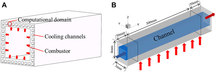
FIGURE 1. Regenerative cooling channels and computational domain. (A) Schematic of a typical scramjet combustor. (B) Single regenerative cooling channel.
The rectangular computational domain is built with a heated length of 300 mm and a fluid region cross section of 2 mm × 2 mm. Four solid walls with a certain thickness are placed around the fluid passage, and fluid–solid coupling is considered. The heat flux is loaded from the outer wall of the combustor, i.e., the bottom wall. Along the normal direction (z-axis) and spanwise direction (y-axis), the wall thickness is, respectively, 1 and 0.5 mm. In order to ensure a fully-developed regime and exclude the effect of boundary development on heat transfer, two extended channels are arranged upstream and downstream with a length of 50 mm.
Thermophysical properties
Thermophysical properties of supercritical n-decane change greatly when the temperature approaches the critical point. It is crucial to get the exact thermophysical properties in the calculation including density, viscosity, thermal capacity, and thermal conductivity. The corresponding data are obtained by SUPERTRAPP software which was developed by the National Institute of Standards and Technology, United States (Huber, 2007). For the three physical properties of density, viscosity, and thermal conductivity, the User-Defined Function was used in FLUENT to input the related data profiles including the temperature and the corresponding physical property data, and then UDF folders were loaded. For the thermal capacity of the fluid, the piecewise-linear function in the fluid material definition panel in FLUENT 19.0 was used to input the points within the computational temperature range. The details of thermophysical properties including density, viscosity, thermal conductivity, and thermal capacity that varied with temperature are shown in Figure 2.
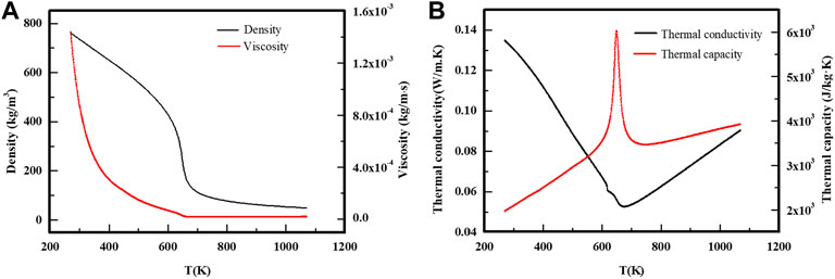
FIGURE 2. Related thermophysical properties of n-decane at 3 MPa obtained from SUPERTRAPP software. (A) Density and viscosity. (B) Thermal conductivity and thermal capacity.
Numerical method and verification
Grid and boundary conditions
In this study, structured grids are adopted to discretize the computational domains by commercial software ANSYS ICEM CFD 19.0. The mesh details of overview and cross sections of streamwise direction are displayed in Figure 3. The k–ω SST model is adopted to solve the turbulence equations. To meet the wall y + requirement of the k–ω SST model, the height of the first layer and the growth rate in the mesh system are set at 0.01 mm and 1.1, respectively. Also, the corresponding wall y+ is less than 1 for all the considered cases.
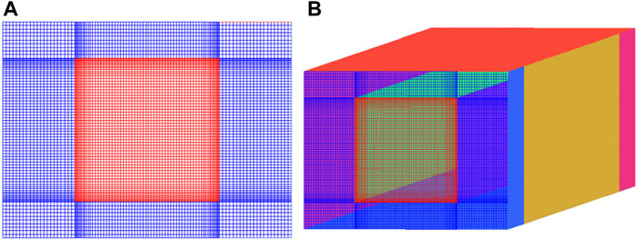
FIGURE 3. Structured meshes and local mesh details. (A) Cross section of the grids. (B) Full view of the grids.
Three-dimensional turbulent flow and heat transfer are performed in the rectangular regenerative cooling channel, as shown in Figure 1. In the calculation, the mass flow rate of the inlet is 0.0028 kg/s with an initial temperature of 423 K, and the corresponding Reynolds number is 5,385. The outlet is set as pressure-outlet with an operation pressure of 3 MPa. It is noted that only the bottom wall is the heated wall with a length of 300 mm. Other sidewalls, including the upstream and downstream extended channel walls, are both set as adiabatic.
To investigate the effects of non-uniform heat flux, four kinds of heat flux distributions, namely, uniform distribution (Case A), sinusoidal distribution (Case B), increased distribution (Case C), and decreased distribution (Case D), are designed. For the sinusoidal distribution of Case B1–Case B4, the cycle of sinusoidal function is change, and amplitude is changed for Case B5–Case B7. For the increased distribution of Case C1–Case C3, the increased rate is changed but setting the same averaged heat flux. Similar to Case C, the decreased rate of Case D1–Case D3 is changed but the same averaged heat flux is maintained. The details of heat flux distribution along the heated wall are provided in Table 1. The non-uniform heat flux distributions in each case are realized by User-Defined Functions in ANSYS FLUENT 19.0. For all the cases, the averaged heat flux is set at 1.5 MW/m2 which provides the convenience for comparisons.
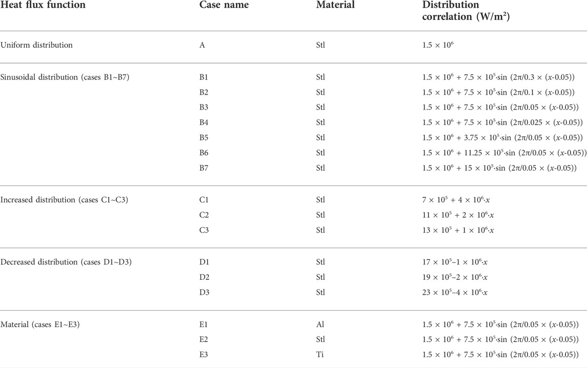
TABLE 1. Wall material and heat flux density of all the cases.
In the calculation, the effects of gravity with a value of 9.81 m/s2 are considered because of the drastic change in thermophysical properties. The interface between fluid and solid domains is coupled, and stainless steel is selected as the wall material in Case A–Case E. The density and thermal capacity of the steel are 7,930 kg/m3 and 500 J/kgK, respectively. The change of thermal conductivity of solid material is also considered in the calculation, and a linear correlation of thermal conductivity is used. The linear correlation of thermal conductivity for the steel is 12.1 W/mK at 290 K and 28.5 W/mK at 1300 K.
Numerical methods and governing equations
The mass, momentum, and energy conversation equations employed are provided in Eqs 1–3, respectively (Yan and Gu 2011; Tang et al. 2020):
The heat conduction formula is given as follows in Eq. 4 Dai et al. (2013):
A verified k–ω SST turbulence model is used in many previous investigations for supercritical fluids and is calculated by Eqs 5–8 Sun et al., (2019):
The finite volume method is implemented to accomplish the discretization of mass, momentum, and energy conservation equations. A double-precision pressure-based steady solver is adopted to get the flow and heat transfer characteristics of supercritical n-decane. The second-order upwind scheme is applied to the discretization, including pressure, momentum, turbulent kinetic energy, specific dissipation rate, and energy. Also, the SIMPLEC scheme is employed to deal with coupling of pressure and velocity. The convergence of the calculation determines that residuals of the continuity equation, velocity components, k and ω items are below 10−5, and the residual of the energy equation is below 10−9. In addition, the temperature on the heated walls is also monitored to judge the convergence.
Model validation and mesh independence study
For numerical simulation, it is necessary to verify the reliability of the turbulence model and determine the sensitivity of the generated meshes. For this work, turbulence model validation is performed by comparing the predicted result with the result of the previous experiment carried out by Liu et al., (2015). The verification of the turbulence model is performed in a circular tube with an inner diameter of 2 mm. The boundary conditions are set the same as the experiments. Four different turbulence models, namely, k–ε reliable, k–ε RNG, k–ω SST, and transition SST, are employed, and the predicted results are compared with experimental data, respectively. The fluid temperature and wall temperature along the streamwise direction are compared in Figure 4.
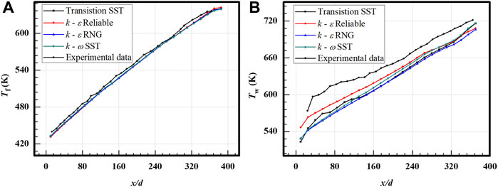
FIGURE 4. Verification of the turbulence model. (A) Fluid temperature. (B) Wall temperature.
As shown in Figure 4, the fluid temperature predicted by different turbulence models overlaps together which is very close to the experimental results. As for wall temperature distributions, the results of the k–ω SST turbulence model also have good agreement with the experimental data, and the error of averaged temperature is less than 5%. From a mechanistic point of view, the k–ω SST model considers the transmission of turbulent tangent stresses, making the SST k–ω model more accurate and reliable to predict a wider range of flows. In addition, the k–ω SST model can predict the flow field well according to the previous research. Therefore, the k–ω SST model is selected.
Figure 5 shows the results of fluid temperature and wall temperature varied along the streamwise direction predicted by the k–ω SST turbulence model. Both the fluid temperature and wall temperature increase along the streamwise direction, and the wall temperature is larger than the fluid temperature to provide the temperature gradient. Like the other turbulence models, the fluid temperature distributions predicted by the k–ω SST model are highly consistent with the experimental data. For wall temperature, the overall relative error is below 5%, and a relatively large error is found upstream of the tube. It is expected that the large error is caused by the upstream extended channel in the simulation work. Some heat is transferred upstream of the tube by the solid wall of the upstream extended channel, and the temperature increase becomes relatively gentle in the simulations. Overall, the k–ω SST turbulence model has shown enough reliability in the simulations.
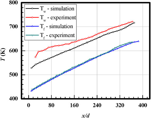
FIGURE 5. Comparison of the fluid and wall temperature, respectively, from the experimental results and predicted by the k–ω SST model.
A mesh independence study is also performed in this work, and Case A is selected to assess the mesh sensitivity. Also, four kinds of mesh regimes are built, respectively, with a grid number of 3.07, 4.32, 5.98, and 8.01 M. Area-weighted averaged temperature on the heated surfaces and the pressure drop between the inlet and outlet predicted by the different mesh regimes are provided to evaluate the mesh sensitivity, as shown in Table 2. From the table, the results of all mesh regimes are very close, especially for the mesh regime of 4.32 and 5.98 M. When the grid number increases from 4.32 to 5.98 M, the error of averaged temperature and pressure drop is below 0.01%. Considering calculation accuracy and computational efforts, the mesh regime of 5.98 M is selected.
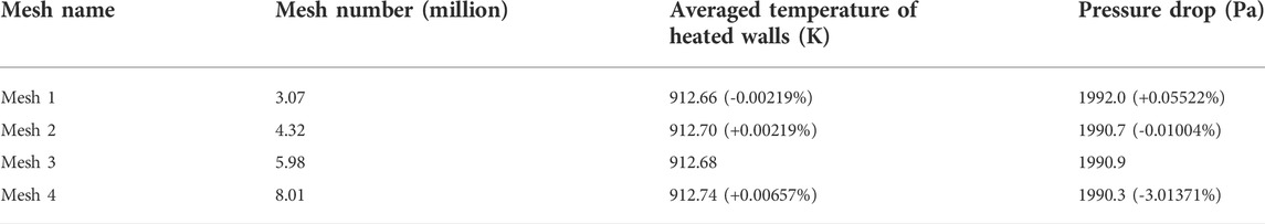
TABLE 2. Related data calculated by different mesh regimes.
Results and discussion
Comparisons of temperature distribution
Figure 6 presents wall temperature trends along the streamwise direction loaded with different heat flux distributions. Each wall temperature value is obtained by averaging the temperature in the cross section within the solid domain perpendicular to the streamwise direction. A series of cross sections are built along the streamwise direction, and the distribution of wall temperature is displayed. The bottom surfaces are heated, and the highest temperature is obtained. The heat is transferred in the solid material from the sidewalls to the top wall. Therefore, the temperature in the sidewalls (left and right surfaces) is medium, and the temperature on the top surface is the lowest.
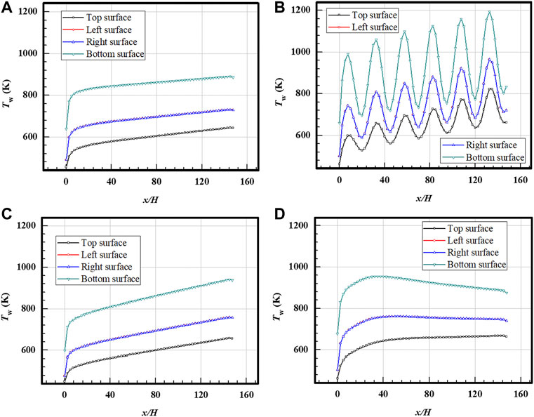
FIGURE 6. Temperature distributions along the streamwise direction on channel walls loaded with different heat flux distributions. (A) Case A; (B) Case B3; (C) Case C2; (D) Case D2.
In Figure 6, four kinds of heat flux distributions are selected, respectively, Case A, Case B3, Case C2, and Case D2. As shown in Figure 6A (the case loaded with the uniform heat flux distribution), the wall temperature has a relatively constant increased ratio in most locations except for a sharp rise at the inlet. In Figure 6B (the case loaded with the sinusoidal heat flux distribution), the wall temperature distribution exhibits a trend of sinusoidal increase which is corresponding to the heat flux distribution imposed on the walls. It is noted that the period of the increased temperature distribution is consistent with the sinusoidal heat flux distribution. The heated bottom wall also provides the highest temperature distribution. In Figure 6C (the case loaded with increased heat flux distribution), the temperature increases more quickly than that in Case A downstream of the thermal boundary fully developed region. The quickly increased wall temperature is caused by the increased wall heat flux along the streamwise direction. In Figure 6D (the case loaded with a decreased heat flux distribution), the wall temperature distribution first increases quickly upstream and then exhibits stably or slowly decreases downstream.
Comparing the four cases with different heat flux distributions in Figure 6, it is found that the wall temperature is greatly affected by the heat flux different distributions. For the uniform case (Case A), the wall temperature increases slowly along the streamwise direction. The distribution trends of the wall temperature have a similarity with the heat flux distribution. When the decreased distribution of heat flux is loaded in Case D, the wall temperature displays a decreased trend after the thermal boundary is fully developed, and the high-temperature region is found upstream. This phenomenon is caused by the large thermal conductivity coefficient in the solid material, and heat diffuses around the solid materials. It is noted that the bottom wall temperature is more affected by the variations of heat flux distributions which are directly loaded with heat flux.
Bulk fluid temperature distributions along the streamwise direction of the aforementioned cases are shown in Figure 7. Each data point in the figure is obtained by area-averaging all the result points of temperature on the y-z section, and 61 y-z sections are built along the streamwise direction. The distribution of heat flux is totally different for all the cases, and the averaged heat flux is the same. Therefore, the same outlet fluid temperature is obtained by all the cases loaded with different heat flux distributions based on the principle of energy conservation. Similar to the wall temperature, fluid temperature distribution also shows the dependency on heat flux distributions. Compared with the wall temperature, the dependency on heat flux distributions is much weakened because the heat is difficult to be transferred reversed in the streamwise direction. Overall, the wall temperature distribution is more sensitive to the variations of heat flux distributions than the fluid temperature.
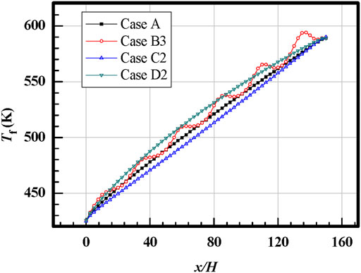
FIGURE 7. Fluid temperature distributions along the streamwise direction for cases loaded with different heat flux distributions.
Streamlines and temperature contours on y-z sections for the case loaded with sinusoidal heat flux distributions (Case B3) are presented in Figure 8. Twelve y-z sections are selected with x/H ranging from 12.5 to 150. From the figure, low-temperature regions are located at the core part of the mainstream. The high-temperature region is mainly located at the bottom. With flow developing along the channel, the high-temperature region approaches the core part of the mainstream. It is noted that the fluid near the walls is heated fast, and the temperature distribution on y-z sections becomes more symmetrical at the end of the heated region. It is concluded that the temperature contours inside the solid walls approach uniform associating with the decreased temperature difference of the heated wall and the mainstream when the mainstream is heated along the channel. Two counter-rotating vortices are found in the y-z sections in Figure 8. The pair of vortices is caused by buoyancy force generated by density variation depending on temperature and gravity effect considered in the computational model. Overall, the mainstream is downward flow in the y-z sections because of higher fluid temperature close to the bottom heated wall. The pair of vortices is pushed to the sidewalls, and upward flows are found in the region close to the sidewalls.
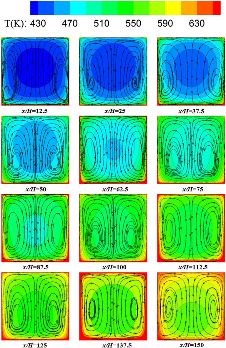
FIGURE 8. Streamlines and temperature contours on y-z sections for the case loaded with sinusoidal heat flux distributions (Case B3).
Streamlines and temperature contours on y-z sections for the cases, respectively, loaded with the increased and decreased heat flux distributions (Case C2 and Case D2) are compared in Figure 9. The same sections in Figure 8 are selected. The temperature characteristics on the y-z sections are affected by the heat flux distributions in Case C2 and Case D2. For the case with an increased heat flux distribution, a large temperature difference exists between the bottom wall and the mainstream, even at the end of the heated region. For the case with a decreased heat flux distribution, the fluid near the wall is heated fast because high heat flux is loaded upstream of the channel. After a long heat diffusion process along the channel, the temperature distribution becomes more symmetrical for Case D2.
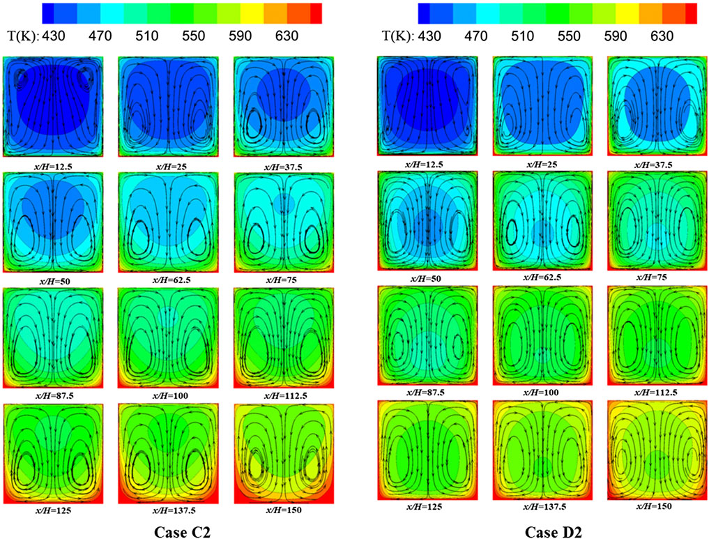
FIGURE 9. Streamlines and temperature contours on y-z sections for the cases, respectively, loaded with the increased and decreased heat flux distributions (Case C2 and Case D2).
Effects of related distribution parameters
To reveal the characteristics of regenerative cooling channels loaded with different kinds of heat flux distributions, effects of related distribution parameters are studied in this section, such as the cycle and amplitude of the sinusoidal distributions and the inclination angle of the increased and decreased distributions.
Figure 10 presents temperature distribution along the streamwise direction loaded with sinusoidal heat flux distributions with different cycles and amplitudes. Each data is obtained by averaging all the data points of temperature on the y-z sections, including fluid temperature (A1 and B1) and wall temperature (A2 and B2). For all the considered cases, the averaged heat flux is set the same. As shown in Figure 10A1 and Figure 10B1, the outlet temperature is kept the same and close to 590 K based on the energy conservation principle. For the cases with different cycles shown in Figure 10A1, the number of heat transfer peaks has an agreement with the cycles of sinusoidal heat flux distributions. Overall, the fluctuations of temperature distribution along the streamwise direction become weakened with the cycles of sinusoidal distributions becoming small even though the same amplitude is applied. When the same cycle is applied, the fluctuations of temperature distribution are increased with the increased amplitude as shown in Figure 10B1. It is noted that when the fluctuation of heat flux distributions is strong enough, the fluid temperature in some regions exceeds the outlet temperature because of the conjugate heat transfer with the solid walls. Compared with the fluid temperature, the wall temperature distributions display a similar trend with stronger fluctuations as shown in Figure 10A2 and Figure 10B2, which have good agreements with the heat flux distributions. The strongly fluctuated wall temperature interacts with the fluid temperature by coupled heat transfer. Overall, the wall temperature is more sensitive to the change in heat flux.
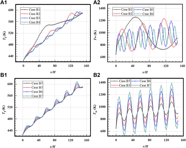
FIGURE 10. Temperature distributions for cases loaded with sinusoidal distributions. (A1) Fluid temperature for cases with different cycles. (A2) Averaged wall temperature for cases with different cycles. (B1) Fluid temperature for cases with different amplitudes. (B2) Wall temperature for cases with different amplitudes.
Temperature distributions for the cases loaded with increased and decreased heat flux distributions at different inclination ratios are provided in Figure 11. Fluid temperature and wall temperature for the cases loaded with increased heat flux distributions are shown in Figure 11A1 and Figure 11A2, and the cases loaded with decreased heat flux distributions are shown Figure 11B1 and Figure 11B2, respectively. Though the same outlet temperature is obtained in all the cases, the variations in the trend of temperature along the streamwise direction are affected by heat flux distributions. For the fluid temperature, the upstream temperature increases slowly and then increases fast along the streamwise direction for the cases with increased heat flux distributions, while the cases loaded with decreased heat flux distributions show a reversed trend. The wall temperature in the outlet region changes greatly for different cases, and it mainly depends on the local heat flux. If the inclination ratio for the cases with increased heat flux distributions is increased, a larger wall temperature is obtained at the outlet of the heated region. When the heat flux distribution is decreased, the upstream wall temperature exceeds the downstream wall temperature at a larger decreased rate. For the cases with a decreased heat flux distribution, the wall temperature becomes relatively stable when a suitable decreased rate is applied.
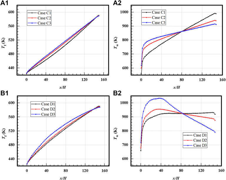
FIGURE 11. Temperature distributions for cases loaded with linear distributions. (A1) Fluid temperature for cases with increased distributions. (A2) Wall temperature for cases with increased distributions. (B1) Fluid temperature for the cases with decreased distributions. (B2) Wall temperature for the cases with decreased distributions.
Temperature contours of the bottom heated walls loaded with different heat flux distributions are displayed in Figure 12. Figure 12A includes the sinusoidal heat flux distributions with the same amplitudes, i.e., Case B1–Case B4. Figures 12B–D, respectively, include Case B5–Case B7, Case C1–Case C3, and Case D1–Case D3. Effects of non-uniform heat flux distributions on wall temperature are more clearly visible in the temperature contours. Several high-temperature regions are found in the cases with the sinusoidal heat flux distributions. With the decreased cycles of the sinusoidal heat flux distributions, the temperature variations become weakened along the streamwise direction, and the overall temperature distribution becomes more uniform, as shown in Case B4. When the decreased heat flux distribution is applied, high-temperature regions move upstream. When a suitable decreased rate is applied, a relatively constant temperature distribution is achieved, as shown in Case D1.
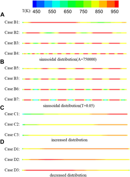
FIGURE 12. Temperature contours on the heated walls for all the cases. (A) Sinusoidal distributions with different cycles. (B) Sinusoidal distributions with different amplitudes. (C) Increased heat flux distributions. (D) Decreased heat flux distributions.
Effects of thermal conductivity
Effects of thermal conductivity are also considered in this work. Fluid temperature and wall temperature loaded with sinusoidal heat flux distributions in the cooling channel with different solid materials are presented in Figure 13. Three kinds of solid materials are used, Al (202.4 W/mK), steel (18.17–26.77 W/mK), and Ti (7.44 W/mK). For the fluid temperature shown in Figure 13A, the same temperature is obtained at the end of the heated wall even with different temperature variations in the heated process. The temperature variations become stronger when a larger thermal conductivity is applied. The phenomenon is also found in the wall temperature distribution shown in Figure 13B. A more fluctuated fluid and wall temperature distribution are found for the cooling channel with low thermal conductivity, i.e., Ti. It is concluded that a larger temperature gradient is found in the solid wall with low thermal conductivity.
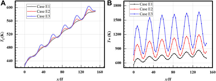
FIGURE 13. Temperature distributions of cases with different thermal conductivities, respectively, Al, steel, and Ti. (A) Fluid temperature. (B) Wall temperature.
Conclusion
In this work, flow structures and heat transfer of hydrocarbon fuel in the regenerative cooling channels loaded with non-uniform heat flux distributions are investigated. Different kinds of heat flux distributions are applied coupled with solid wall heat conduction, including uniform heat flux distributions, sinusoidal heat flux distributions, increased heat flux distributions, and decreased heat flux distributions. Related parameters of distribution curves are fully analyzed to reveal the flow and heat transfer characteristics loaded with non-uniform heat flux distributions. In addition, effects of gravity and thermal conductivity of solid materials are also considered in this work. Some useful conclusions that emerged from this study are provided as follows:
1) The fluid temperature at the outlet of the heated channel is only determined by the averaged heat flux, and all the regenerative cooling channels achieve the same temperature although loaded with different heat flux distributions. The wall temperature is greatly affected by the heat flux distributions and displays a similar trend with the corresponding loaded heat flux distributions. Compared with the fluid temperature, the wall temperature distribution is much sensitive to the variation of heat flux distribution.
2) The regenerative cooling channels loaded with the sinusoidal heat flux distributions exist in several high-temperature regions according to the peaks of the sinusoidal curve, and the fluctuations of temperature distribution along the streamwise direction become weakened with the cycles of sinusoidal distributions becoming small. The heat flux with linear distributions can change the trend of temperature distribution. For the cooling channel with decreased heat flux distributions, an almost uniform temperature field distribution is achieved at a suitable decreased rate of heat flux, such as Case D1.
3) For the effect of thermal conductivity, a larger temperature gradient is found in the regenerative cooling channel wall with lower thermal conductivity. This work provides a good insight into the characteristics of the flow and temperature field of regenerative cooling channels loaded with non-uniform heat flux considering the conjugate heat transfer effect.
Data availability statement
The original contributions presented in the study are included in the article/Supplementary Material; further inquiries can be directed to the corresponding author.
Author contributions
All authors listed have made a substantial, direct, and intellectual contribution to the work and approved it for publication.
Funding
The research work is financially supported by the start-up funds of Central South University (202045012).
Conflict of interest
The authors declare that the research was conducted in the absence of any commercial or financial relationships that could be construed as a potential conflict of interest.
Publisher’s note
All claims expressed in this article are solely those of the authors and do not necessarily represent those of their affiliated organizations, or those of the publisher, the editors, and the reviewers. Any product that may be evaluated in this article, or claim that may be made by its manufacturer, is not guaranteed or endorsed by the publisher.
References
Brinda, R., Daniel, R. J., and Sumangala, K. (2016). Effect of aspect ratio on the ladder type triangle micro channels employed micro cooling systems. Int. J. Enterp. Netw. Manag. 7, 172. doi:10.1504/IJENM.2016.077532
Chen, Y., Wang, Y., Bao, Z., Zhang, Q., and Li, X.-Y. (2016). 'Numerical investigation of flow distribution and heat transfer of hydrocarbon fuel in regenerative cooling panel. Appl. Therm. Eng. 98, 628–635. doi:10.1016/j.applthermaleng.2015.12.088
Dai, B., Zheng, B., Liang, Q., and Wang, L. (2013). 'Numerical solution of transient heat conduction problems using improved meshless local Petrov–Galerkin method. Appl. Math. Comput. 219, 10044–10052. doi:10.1016/j.amc.2013.04.024
Ding, R., Wang, J., He, Fei, Dong, G., and Tang, L. (2019). 'Numerical investigation on the performances of porous matrix with transpiration and film cooling. Appl. Therm. Eng. 146, 422–431. doi:10.1016/j.applthermaleng.2018.09.134
Feng, Y., Cao, J., Li, X., Zhang, S., Jiang, Q., Yu, R., et al. (2017). 'Flow and heat transfer characteristics of supercritical hydrocarbon fuel in mini channels with dimples. J. Heat. Transf. 139, 122401. doi:10.1115/1.4037086
Han, Z., Zhou, W., Yu, W., and Jia, Z. (2021). 'Experimental investigation on heat transfer of n-decane-ZnO nanofluids in a horizontal tube under supercritical pressure. Int. Commun. Heat Mass Transf. 121, 105108. doi:10.1016/J.ICHEATMASSTRANSFER.2021.105108
Huber, M. (2007). NIST 4. thermophysical properties of hydrocarbon mixtures database: version 3.0, world wide web-internet and web information systems, Online. Available at: https://tsapps.nist.gov/publication/get_pdf.cfm?pub_id=200144 (Accessed August 7, 2022).
Jin, X., Shen, C., Wu, Xianyu., and Yan, Li (2020). 'Numerical study on regenerative cooling characteristics of kerosene scramjets. Int. J. Aerosp. Eng. 2020, 1–12. doi:10.1155/2020/8813929
Jing, T., He, G., Li, W., Qin, F., Wei, X., Liu, Y., et al. (2017). 'Flow and thermal analyses of regenerative cooling in non-uniform channels for combustion chamber. Appl. Therm. Eng. 119, 89–97. doi:10.1016/j.applthermaleng.2017.03.062
Li H, H., Jiang, Q., Jiang, Y., Zhou, W., Wen, B., Huang, H., et al. (2019). 'Experimental study on the thermodynamic characteristics of the high temperature hydrocarbon fuel in the cooling channel of the hypersonic vehicle. Acta Astronaut. 155, 63–79. doi:10.1016/j.actaastro.2018.11.021
Li X, X., Xie, G., Liu, J., and Sunden, B. (2020). 'Parametric study on flow characteristics and heat transfer in rectangular channels with strip slits in ribs on one wall. Int. J. Heat Mass Transf. 149, 118396. doi:10.1016/j.ijheatmasstransfer.2019.07.046
Li Y, Y., Xie, G., and Sunden, B. (2020). 'Flow and thermal performance of supercritical n-decane in double-layer channels for regenerative cooling of a scramjet combustor. Appl. Therm. Eng. 180, 115695. doi:10.1016/j.applthermaleng.2020.115695
Li, Y., Sun, F., Xie, G., and Jiang, Q. (2018). 'Improved thermal performance of cooling channels with truncated ribs for a scramjet combustor fueled by endothermic hydrocarbon. Appl. Therm. Eng. 142, 695–708. doi:10.1016/j.applthermaleng.2018.07.055
Li Z, Z., Wang, H., Jing, K., Wang, L., Yu, L., Zhang, X., et al. (2019). 'Kinetics and modeling of supercritical pyrolysis of endothermic hydrocarbon fuels in regenerative cooling channels. Chem. Eng. Sci. 207, 202–214. doi:10.1016/j.ces.2019.06.019
Liu, B., Zhu, Y., Yan, J.-J., Lei, Y., Zhang, B., Jiang, P.-X., et al. (2015). 'Experimental investigation of convection heat transfer of n-decane at supercritical pressures in small vertical tubes. Int. J. Heat Mass Transf. 91, 734–746. doi:10.1016/j.ijheatmasstransfer.2015.07.006
Liu, C., Zhang, J., Jia, D., and Li, P. (2022). 'Experimental and numerical investigation of the transition progress of strut-induced wakes in the supersonic flows. Aerosp. Sci. Technol. 120, 107256. doi:10.1016/J.AST.2021.107256
Luo, W., Han, H., Jiang, R., Yu, R., and Zhu, Q. (2022). '3D numerical investigation of trans-critical heat transfer enhancement in regeneration cooling channel with crescent rib. Int. J. Therm. Sci. 172, 107287. doi:10.1016/J.IJTHERMALSCI.2021.107287
Peszynski, K., and Tesař, V. (2020). 'Algebraic model of turbulent flow in ducts of rectangular cross-section with rounded corners. Flow Meas. Instrum. 75, 101790. doi:10.1016/j.flowmeasinst.2020.101790
Pu, H., Li, S., Dong, M., Jiao, S., and Shang, Y. (2018). 'Numerical method for coupled thermal analysis of the regenerative cooling structure. J. Thermophys. Heat Transf. 32, 326–336. doi:10.2514/1.t5224
Ruan, B., Huang, S., Meng, H., and Gao, X. (2017). 'Flow dynamics in transient heat transfer of n-decane at supercritical pressure. Int. J. Heat Mass Transf. 115, 206–215. doi:10.1016/j.ijheatmasstransfer.2017.08.038
Su, C. H., Gao, F., Zhang, Q., Xiao, H., Zhang, C., and Xia, X. (2020). 'Modeling and analysis of regenerative cooling channels for scramjet engine. MATEC Web Conf. 316, 03002. doi:10.1051/matecconf/202031603002
Sun, F., Li, Y., Sunden, B., and Xie, G. (2019). 'The behavior of turbulent heat transfer deterioration in supercritical hydrocarbon fuel flow considering thermal resistance distribution. Int. J. Therm. Sci. 141, 19–32. doi:10.1016/j.ijthermalsci.2019.03.027
Tang, L., Cao, Z., and Pan, J. (2020). 'Investigation on the thermal-hydraulic performance in a PCHE with airfoil fins for supercritical LNG near the pseudo-critical temperature under the rolling condition. Appl. Therm. Eng. 175, 115404. doi:10.1016/j.applthermaleng.2020.115404
Ulas, A., and Boysan, E. (2013). 'Numerical analysis of regenerative cooling in liquid propellant rocket engines. Aerosp. Sci. Technol. 24, 187–197. doi:10.1016/j.ast.2011.11.006
Wang, N., and Pan, Y. (2020). 'Correlation for heat transfer of RP-3 kerosene flowing in miniature tube at supercritical pressures. Mod. Phys. Lett. B 34, 2050116. doi:10.1142/S021798492050116X
Wörz, B., Wieler, M., Viola, D., Peter, J., and Rabs, M. (2019). Heat transfer in a square ribbed channel: Evaluation of turbulent heat transfer models. Int. J. Turbomach. Propuls. Power 4, 18. doi:10.3390/ijtpp4030018
Xu, K., and Meng, H. (2016). 'Numerical study of fluid flows and heat transfer of aviation kerosene with consideration of fuel pyrolysis and surface coking at supercritical pressures. Int. J. Heat Mass Transf. 95, 806–814. doi:10.1016/j.ijheatmasstransfer.2015.12.050
Xu, Q., Lin, G., and Li, H. (2021). 'Evaluation model for fast convective heat transfer characteristics of thermal cracked hydrocarbon fuel regenerative cooling channel in hydrocarbon-fueled scramjet. Appl. Therm. Eng. 199, 117616. doi:10.1016/J.APPLTHERMALENG.2021.117616
Yan, B. H., and Gu, H. Y. (2011). 'CFD analysis of flow and heat transfer of turbulent pulsating flow in a tube in rolling motion. Ann. Nucl. Energy 38, 1833–1841. doi:10.1016/j.anucene.2011.05.020
Yan, J., Liu, S., Guo, P., and Bi, Q. (2020). 'Experiments on heat transfer of supercritical pressure kerosene in mini tube under ultra-high heat fluxes. Energies 13, 1229. doi:10.3390/en13051229
Zhang, M., and Sun, B. (2020). 'Mechanism and influence factor analysis of heat transfer deterioration of transcritical methane. Int. J. Energy Res. 44, 9050–9063. doi:10.1002/er.5614
Zhang, S., Li, X., Zuo, J., Jiang, Q., Cheng, K., Yu, F., et al. (2020). Research progress on active thermal protection for hypersonic vehicles. Prog. Aerosp. Sci. 119, 100646. doi:10.1016/j.paerosci.2020.100646
Zhang, S., Yu, F., Zhang, D., Jiang, Y., Jiang, Q., Wen, B., et al. (2016). 'Parametric numerical analysis of regenerative cooling in hydrogen fueled scramjet engines. Int. J. Hydrogen Energy 41, 10942–10960. doi:10.1016/j.ijhydene.2016.03.176
Zhao, G., Sun, M., Wang, H., and Ouyang, H. (2018). 'Investigation of combustion characteristics in a scramjet combustor using a modified flamelet model. Acta Astronaut. 148, 32–40. doi:10.1016/j.actaastro.2018.04.005
Zhu, Y., Peng, W., Xu, R., and Jiang, P. (2018). Review on active thermal protection and its heat transfer for airbreathing hypersonic vehicles. Chin. J. Aeronautics 31, 1929–1953. doi:10.1016/j.cja.2018.06.011
Zuo, J., Wei, D., Zhang, S., Jiang, Q., Wen, B., Cui, N., et al. (2021). 'Parametric numerical analysis on the interaction between combustion and hydrocarbon fueled supersonic film cooling. Aerosp. Sci. Technol. 111, 106535. doi:10.1016/J.AST.2021.106535
Zuo, J., Zhang, S., Jiang, Q., Wen, B., and Cui, N. (2018). 'Performance evaluation of regenerative cooling/film cooling for hydrocarbon fueled scramjet engine. Acta Astronaut. 148, 57–68. doi:10.1016/j.actaastro.2018.04.037
Nomenclature
Latin characters
Cp fluid thermal capacity (J/kg·K)
d turbulent kinetic energy (m2/s2)
D outer diameter of the circular pipe (m)
H height of the channel (m)
k turbulent kinetic energy (m2/s2)
P pressure (Pa)
T temperature (K)
u velocity (m/s)
x streamwise direction
y spanwise direction
z normal direction
Greek symbols
β thermal expansion coefficient (W/m·K)
λ thermal conductivity (W/m·K)
μ fluid dynamic viscosity (Pa·s)
ρ fluid density (kg/m3)
ω specific energy dissipation rate (s−1)
Subscripts
f fluid
s solid
avg average
Keywords: regenerative cooling, non-uniform, material, temperature distribution, conjugate heat transfer
Citation: Liu J, Xu M, Ma K, Liu C and Xi W (2022) Heat transfer and flow structures of supercritical n-decane in a regenerative cooling channel loaded with non-uniform heat flux. Front. Energy Res. 10:985220. doi: 10.3389/fenrg.2022.985220
Received: 03 July 2022; Accepted: 18 July 2022;
Published: 25 August 2022.
Edited by:
Xiao Liu, Harbin Engineering University, ChinaReviewed by:
Shao-Fei Zheng, North China Electric Power University, ChinaYiheng Tong, Space Engineering University, China
Feng Zhang, Hunan University, China
Jin-yuan Qian, Zhejiang University, China
Copyright © 2022 Liu, Xu, Ma, Liu and Xi. This is an open-access article distributed under the terms of the Creative Commons Attribution License (CC BY). The use, distribution or reproduction in other forums is permitted, provided the original author(s) and the copyright owner(s) are credited and that the original publication in this journal is cited, in accordance with accepted academic practice. No use, distribution or reproduction is permitted which does not comply with these terms.
*Correspondence: Wenxiong Xi, MTM3MzkwNzYwODFAMTYzLmNvbQ==