 Jaemun Choi1
 Jaehun Choi
 Hwabhin Kwon
 Heesung Park
- 1Smart Manufacturing Division, Graduate School of Mechanical Engineering, Changwon National University, Changwon, South Korea
- 2Department of Mechanical Engineering, Changwon National University, Changwon, South Korea
Experimental investigations have been conducted to improve the cooling effectiveness of film-cooling technology. A multiple row of cylindrical holes at the flat surface was considered by inclining the holes at 35° along the streamwise direction. A low-speed wind tunnel with the main flow speed of 10 m/s was devised to create a cross flow at a Reynolds number of 196,167 and five blowing ratios of 0.3, 0.5, 0.7, 1, and 2. The proposed triangular-shaped thin plate and flop at the cylindrical film cooling hole were investigated using flow visualization and thermographic techniques. The resulting cooling performances were also experimentally evaluated and compared with respect to the different film-cooling hole configurations. The typical film cooling hole configuration of cylindrical hole shape shows the cooling effectiveness of 0.1 at blowing ration of 1.0. It should be denoted that this cooling effectiveness is exemplary value of wide range of gas turbine applications. We also experimentally evaluates the cooling effectiveness in order to valid our experimental method. Meanwhile, with triangular-shaped thin plate-flop, the flow detachment is successfully prevented with requiring 8% increase of discharge coefficient. In addition, the film flow is stable even at the distant downstream, resulting in enhanced cooling performance compared to the cylindrical and triangular-shaped thin plate. Consequently, a 242.7% improvement in film cooling effectiveness can be achieved with a triangular-shaped thin plate-flop than with a cylindrical hole owing to its enhanced film coverage.
1 Introduction
With the growing population and industrialization, the global electricity demand has been steadily increasing. Simultaneously, the reduction of greenhouse gas emissions requires highly efficient power plant systems. Gas turbine power plants are one of the large-scale power generation techniques and have become low-emission and efficient energy systems by combining heat recovery steam generators and steam turbines (Nondy and Gogoi, 2020). In addition, highly effective gas turbines should have a high inlet temperature accompanied by superior thermal protection of hot section components (Zhang et al., 2020). To achieve higher efficiency of a gas turbine power plant, an increase in the turbine inlet temperature should be allowed; however, the limitation of turbine blade materials prevents an increase in the inlet temperature. Numerous studies have been conducted to address this problem. Among these, film cooling is one of the most promising technologies that enables a high inlet temperature by protecting the hot section component from overheating (Fu et al., 2018; Huang et al., 2018). The key feature of film cooling is the formation of a thin and cooled area on the surface of the turbine blade. The cooler gas was ejected from the blade through discrete holes on the surface. This film cooling provides an external cooling technique that helps protect the metal surface from hot mainstream gases (Waye and Bogard, 2007). In this study, the performance of film cooling was evaluated by considering the temperature difference and blowing ratio between the mainstream flow and cooler gas flow. Over the last decade, numerous studies have reported the enhancement of film cooling towards hole exit, console holes, fan-shaped holes, and laidback fan-shaped holes (Khalatov et al., 2020). This research on advanced film-cooling technology is extremely significant and urgent (An et al., 2017). In addition, this advanced cooling technology can be applied to high temperature gas turbine of hot section components, such as guide vanes, blades, combustor liner, and exhaust nozzle.
A major problem with film cooling is that the cooler gas tends to detach from the surface of interest owing to the vortex induction from the counter-rotating-vortex structures in the jet flow (Zhou and Hu, 2016). The impact of anti-vortex hole design on the film-cooling performance was studied by Al-Zurfi et al. (2019). Their findings showed that the presence of side holes can restrain the counter-rotating vortex pair intensity of the main hole to decrease coolant lift-off, resulting in improved film cooling coverage. They also demonstrated better performance in reducing the vortex pair intensity when applying downstream side holes. Kim et al. (2021) adopted effusion and transpiration cooling techniques with a multiple hole-array of 0.5 mm diameter and a pore structure of 40 μm diameter. They reported an enhancement of the cooling effectiveness of up to 34% compared to the internal cooling scheme. Although the impact of hole imperfections owing to the thermal barrier coating spallation or manufacturing problem (Bunker, 2000; Jovanovic et al., 2005), a certain film cooling hole blockage can lead to increased cooling effectiveness (Huang et al., 2018). They asserted that hole blockage caused flow complications that affect cooling effectiveness depending on the hole blockage orientation. Yu et al. (2020) examined the film cooling effectiveness of a diffusion slot hole on a blade surface using a pressure-sensitive paint technique. A wider film cooling coverage was obtained using a diffusion slot hole in comparison with the typical fan-shaped hole. This was because of the longer coolant trace and improved attachment of the coolant flow on the surface. The effect of internal cross flow velocity on film cooling effectiveness using axial and compound angle-shaped holes was studied by McClintic et al. (2018a) and McClintic et al. (2018b). They revealed that a higher film cooling flow rate caused a greater sensitivity of film cooling effectiveness to the cross-flow velocity. Ramesh et al. (2016) investigated the film-cooling performance of tripod hole designs. They showed that the presence of rounded corners or webbing did not lower the performance of the tripod cooling holes. As a result, the heat transfer coefficient measurements and the overall heat flux ratios further corroborated the thermal advantages of the tripod hole design over traditional cylindrical and shaped holes. Liu et al. (2020) conducted a numerical simulation to investigate the effect of a converging slot hole on film cooling effectiveness and heat transfer. They found that the counter-rotating vortex pairs near the centerline were induced by the in-tube vortex, which impacted the cross flow and blowing ratio. Fawzy et al. (2020) suggested double lateral sub-hole models with different lateral angles. They showed a highly improved cooling performance of 44% with an optimized blowing ratio of 2.5. Khajehhasani and Jubran (2016) numerically investigated the film-cooling performance by installing four sister holes. They reported that vortices were suppressed by the sister-hole flow, and consequently, the overall cooling effectiveness was improved. Huang et al. (2020) presented a multi-objective optimization method for round-to-slot film-cooling holes. Their numerical simulations optimized the discharge coefficient and film cooling effectiveness by considering different round-to-slot hole geometric parameters.
The improvement in film cooling performance in terms of span-wise and stream-wise directions is significant. In a recent study, hole blockage owing to imperfections implied the enhancement of film cooling flow by suppressing the in-tube vortex (Huang et al., 2018). The motivation of this study is to find the way of suppressing the vortex structure with modifying the film cooling holes. The proposed concept of this study was to install a triangle-shaped thin plate (TSTP), which is expected to alleviate the strong vortex. In addition, the effect of the TSTP installation at the cooling hole on the film cooling effectiveness and coolant discharge coefficient were experimentally investigated. The discharge parameter is important because it relates to the actual mass flow rate required to bleed the pressure of the cooling air (Huang et al., 2020). Therefore, we chose a typical injection angle of 35° along the streamwise direction. A TSTP with a thickness of 0.1 mm was placed at the exit of the cooling hole. The results showed that the proposed TSTP improved the overall cooling effectiveness by 242.7% with only an 8.0% decrease in the discharge coefficient at a blowing ratio of 1.0. The contribution of this suggestion is to futuristic design variation of the film cooling holes without significant increase of discharge coefficient of cooling flow.
2 Experimental
Experiments were conducted in a custom-made open-loop wind tunnel driven by a 15 HP adjustable speed blower. The wind tunnel comprises mainstream and coolant supply parts.
2.1 Experimental setup
As shown in Figure 1, the mainstream was provided by the blower with a flow rate of 54.1 m3/h. A power supply was installed to operate the blower. The mainstream flowed sequentially through an expansion duct with the screen and honeycomb installation to settle the stable flow. In the contraction section, the mainstream entered the test section with a contraction ratio of 9:1. The control box provides an electrical signal to produce the desired flow rate of the blower. An electric heater of 2 kW was used to allow the temperature difference between the mainstream and coolant flows.
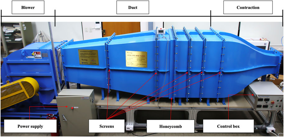
FIGURE 1. Experimental setup for main flow generation.
Figure 2 shows a schematic of the test section. The test section was made of 3D-printed material to produce an approximate adiabatic condition. The apparent sizes of the test section were 300, 300, and 1,000 mm in width, height, and length, respectively. The top of the test section was made of sapphire glass (Al2O3), which offered a good refractive index for infrared (IR) thermal imaging systems. A test plate with film cooling holes was placed at the bottom of the test section, where the secondary flow plenum was assembled for film cooling. The size of the plenum was 260 mm × 260 mm. A screen was installed inside the plenum to ensure coolant flow uniformity. To provide the desired blowing ratios, the coolant flow rate was precisely controlled using a mass flow controlling system. An IR camera was placed above the test section, where a sapphire glass window was installed. In addition, a CCD camera with a sheet laser was placed above the test plate to acquire images of the film cooling flow. Specially designed jigs for mounting the CCD camera and sheet laser were invented to precisely capture the motion of the coolant flow. A fog generator was installed at the plenum of coolant flow and enabled visualization of the film cooling flow. A pitot tube, hot-wire anemometer, and thermocouple were inserted at the inlet of the test section to monitor the pressure, velocity, and temperature of the mainstream. The static pressure was also measured through a pressure tap on the side wall of the test section. The mainstream inlet velocity was calibrated using the measured total pressure and static pressure. The temperature difference between the mainstream and coolant flow was monitored using a thermocouple and a data acquisition system throughout the experiments. All the signals from the sensors were collected using a data acquisition system with a computer.
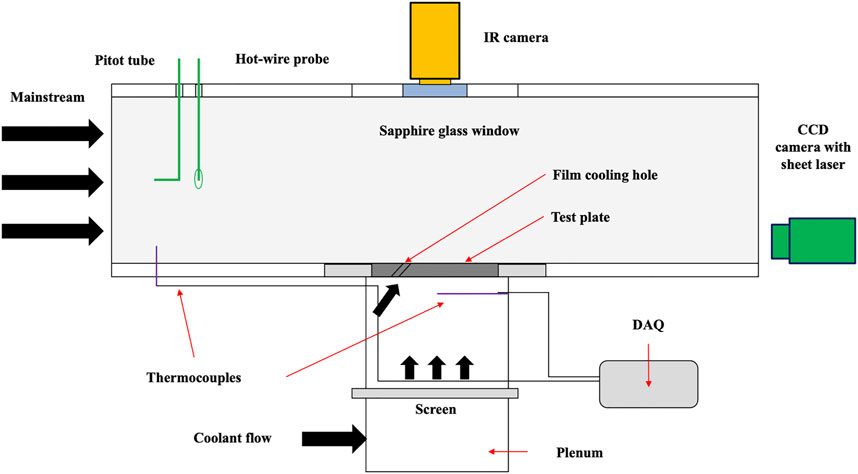
FIGURE 2. Schematic diagram of test section.
The geometric configuration of the test plate is shown in Figure 3. A test plate with a thickness of 15 mm was fabricated using 3D printing technology based on additive manufacturing technologies. The test plate was made of photosensitive resin with a thermal conductivity of 0.19 W/m K. Three different test plates were prepared for the cylindrical shape, TSTP, and TSTP-flop, respectively. The size of the suggested TSTP was an equilateral triangle with a side length of 10 mm. The TSTP was placed at the hole trailing edge, whereas the TSTP-flop was placed at the hole leading edge. Each plate had seven film holes in one row to investigate the spanwise flow and cooling performance. The surface condition and film hole diameter were optically inspected to eliminate the need for additional processing. The average roughness of the hole wall was Ra = 1.32 μm according to our measurement. Because most turbine blade geometries use angled injection to the film cooling flow, we adopted an angle of injection of 35° in the experiment. Note that the spatial distance between the film cooling holes was set to 4 D, while the measurement of cooling performance in the streamwise direction was conducted at a distance of 20 D. D represents the film hole diameter in this study, and it is 5 mm.
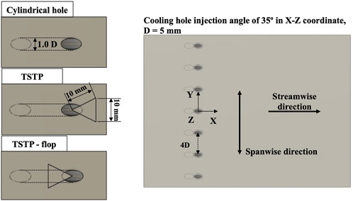
FIGURE 3. Design configuration for the cylindrical hole, TSTP, and TSTP-flop. The coordinate and the directions are displayed.
The operating conditions of the experiments are summarized in Table 1. The mainstream velocity (Um) was 10 m/s, which produced a Reynolds number (Rem) of 196,167. The turbulence intensity of the mainstream at the inlet of the test section was measured to be 0.32%. The temperature difference developed by the electrical heater was 295.7–322.5 K, which were monitored by thermocouples. The tested blowing ratios (M) were 0.3, 0.5, 0.7, 1, and 2, respectively. The corresponding Reynolds numbers of the coolant flow were 1,001, 1,602, 2,322, 4,004, and 6,657, respectively. The selection of the operating condition was based on the consideration of real gas turbine operation. Nonetheless, the limits of lab-scale experimental setup restrained the temperature and flow rate range. With these experimental parameters, the effect of TSTP design can be successfully evaluated.
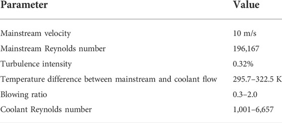
TABLE 1. Experimental parameters and test conditions.
In this study, three different hole geometries were experimentally investigated using film flow visualization and cooling performance. The basic ideas of the size and geometric design in this experimental investigation were to evaluate practical cooling performance by considering high temperature gas turbine system. It should be denoted that the cylindrical hole shape was represented to typical film cooling hole configuration, while the TSTP and TSTP-flop were designed to alternative configuration for film cooling. The effect of hole blockage by the suggested triangle shape is analyzed and discussed in the following section. Through the paper, the cylindrical hole shape represented the typical and widely used film cooling configuration in gas turbine applications. Thus, all the results can be regarded to the comparison between typical and suggested film cooling hole configurations.
2.2 Film cooling parameters
The blowing ratio (M) can be defined using the densities and velocities of the mainstream and coolant flows, as described in Eq. 1.
Here, ρ and U represent the density and velocity, respectively, while the subscripts m and c represent the mainstream and coolant flows, respectively. The cooling effectiveness (η) can be evaluated based on the temperature differences between the mainstream and coolant flows.
where T represents the temperature and the subscript of w is the wall of the test plate. In this study, the wall temperature was measured using an IR camera through a sapphire glass window. The discharge coefficient (Cd) is a significant parameter for determining the effectiveness of film cooling performance in terms of the required coolant flow rate with a pressure drop. Thus, Cd represents the power consumed by the resulting cooling performance. As defined in Eq. 3, the discharge coefficient is proportional to the mass flow rate of the coolant (mc), whereas it is inversely proportional to the pressure difference between the total pressure (p∗c) of the film-cooling entrance and the static pressure (pc) of the film cooling exit. Thus, a higher discharge coefficient leads to improved cooling performance because of the lower pressure drop.
where Ac denotes the inlet area of the film-cooling hole. Consequently, the cooling effectiveness can be evaluated experimentally for the three different film-cooling hole types, and further analyses can be conducted using the discharge coefficient with varying blowing ratios.
3 Results and discussion
First, our experimental results were compared with previously published data in the literature. In Figure 4, the spanwise-averaged film cooling effectiveness at a blowing ratio of 1.0, is plotted with regard to the present study and previous data (Goldstein et al., 1970; Pedersen et al., 1977; Schmidt et al., 1996). It should be denoted that in Figure 4, all the experiments were conducted with cylindrical hole, film hole cooling, and injection angle of 30°–35°. This shows that our experimental results match well enough to validate. As a result, the data were within an acceptable error margin compared with previous data.
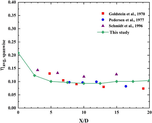
FIGURE 4. Experimental validation by comparison between published data and this study.
An experimental uncertainty was conducted with relevant parameters by using the procedure described in Holman (Holman, 2011). The uncertainty values were dominant by the limits of measurement devices of flow rates and temperatures. The uncertainties of Reynolds number, blowing ratio and cooling effectiveness were 1.0, 3.9 and 5.2%, respectively.
3.1 Film cooling flow visualization and characteristics
Figure 5 shows the captured images captured by the CCD camera while injecting artificial fog through the film cooling holes. The desired blowing ratio was set up by controlling the coolant flow rate. The mainstream flow rate and coolant flow rate were divided by the test section area and film cooling hole area, respectively, to evaluate Um and Uc. The densities of the mainstream and coolant flows were defined for each measured temperature. Note that the cross-sectional view at the center of the cooling hole is in the X-Z coordinate. The coolant opening area and the placements of the TSTP and TSTP-flop are marked in the figures. The four green arrows are also presented to indicate the coolant flow region. As the blowing ratio increases, a more detached film flow can be observed, as in the cylindrical hole as shown in Figure 5A. Right behind the coolant hole, the coolant jet penetration becomes stronger as the blowing ratio increases, which induces pressure buildup, resulting in large vortices (An et al., 2017; Wang et al., 2021). In addition, the coolant flow tends to disperse downstream, which is expected to lead to low cooling effectiveness. Meanwhile, Figure 5B shows different film flow structure. The TSTP removes jet penetration by blockage; however, the dispersed film flow downstream is inevitable. The reason is that the film cooling flow opening to the main flow direction induces flow mixing at the upstream of the cooling hole. When TSTP-flop is applied as shown in Figure 5C, the jet penetration is successfully prevented and film flow is stable even downstream, which is expected to have a better cooling performance than the cylindrical and TSTP. The flow visualizations are also displayed in the in-plane view (X-Y coordinate), as shown in Figure 6. The sheet laser light was applied 1 mm above the film cooling holes, where the CCD camera captured the flow stream. For cylindrical film cooling holes, the flow detachment right behind the film cooling hole was developed with an increased blowing ratio. This is evident in the momentum increase and potential vortex pair (Fric and Roshko, 1994; Kelso et al., 1996; Blanchard et al., 1999). The flow structures of cylindrical hole, TSTP, and TSTP flop can be clearly discriminated by comparing Figures 6A–C, respectively. When the TSTP was placed, the flow detachment disappeared owing to the partially blocked film cooling hole. The upstream of the film cooling was improved. However, as the blowing ratio increased, the film flow dispersion accelerated, as can be observed in Figures 5, 6. That is, the TSTP had no impact on the downstream cooling performance. As shown in Figure 6, the TSTP-flop suppressed the flow separation in the upstream region without significant flow dispersion in the downstream region. These in-plane flow visualizations helped to qualitatively understand the flow characteristics and the effect of the TSTP installation. The effect of increased blow ratio can also be clearly presented by comparing the three different cooling hole designs.
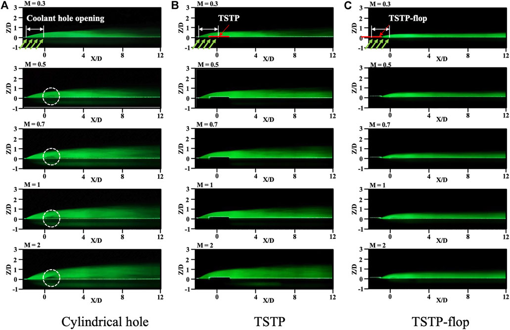
FIGURE 5. Flow field visualization with varying blowing ratios for 0.3 to 2.0 in the center plane of the X-Z coordinate. Three columns represent cylindrical hole, TSTP, and TSTP-flop, respectively.
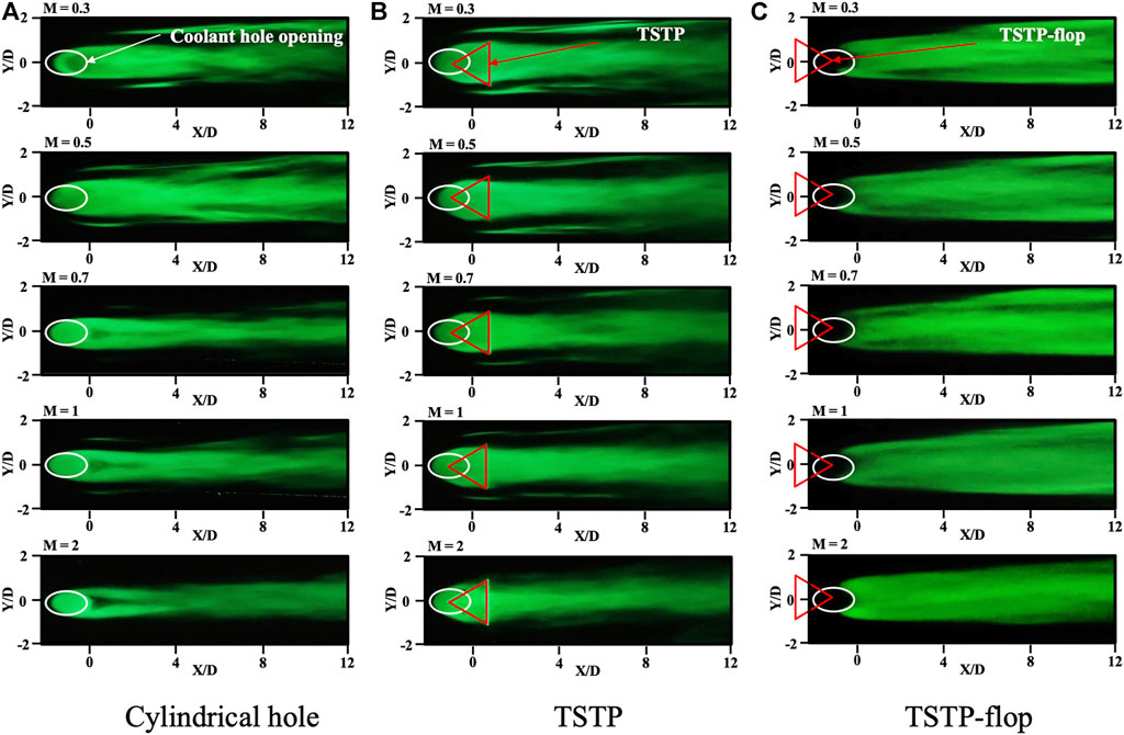
FIGURE 6. Flow field visualization with varying blowing ratios for 0.3 to 2.0 in the center plane of the X-Y coordinate. Three columns represent cylindrical hole, TSTP, and TSTP-flop, respectively.
3.2 Film cooling effectiveness
Figure 7 shows the resulting film cooling effectiveness with respect to the cylindrical hole, TSTP, and TSTP-flop. The measured temperatures of Tm and Tc and the thermographic data of Tw were calculated using Eq. 2. The evaluated film cooling effectiveness is displayed in the colored contours. Corresponding to the flow characteristics displayed in Figure 5A and Figure 6A, the flow separation at the right bound to the cylindrical hole was detrimental to the cooling effectiveness, which drastically decreased as the blowing ratio increased to 2 as displayed in Figure 7A. When the blowing ratios were 0.3 and 0.5, the cooling effectiveness varied from 0.3 to 0.6. However, the cooling effectiveness decreased to 0.1 owing to the flow separation and dispersion downstream. As mentioned before, when the film cooling flow and main flow were in the same direction, flow mixing prevailed resulting in dispersed of cooling flow at the downstream. This trend was observed when applying TSTP, even though flow separation was prevented, as shown in Figure 7B. As observed in Figure 5B and Figure 6B, the flow characteristics reflected the decreased cooling effectiveness. Meanwhile, Figure 7C shows an interesting cooling effectiveness distribution compared with Figures 7A,B. It can be observed that the TSTP-flop played a significant role as expected as seen in Figure 7C. The suppressed flow separation and the less dispersed film flow retained the high film cooling effectiveness from 0.45 to 0.9 when the blowing ratio was 0.3. As the blowing ratio increased to 2.0, the nature of the momentum increased with the use of a cylindrical hole, limiting the cooling effectiveness. Considering the flow visualizations shown in Figure 5C and Figure 6C, TSTP-flop successfully prevented flow separation as well as flow dispersion at the downstream. However, it still showed relatively higher cooling effectiveness than the cylindrical hole and TSTP. The resulting film cooling effectiveness was above 0.45 when the blowing ratio was 2.0. Further increase of cooling performance with respect to high blowing ratio requires more vigorous cooling hole shape design in future studies.
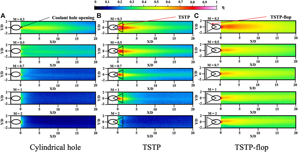
FIGURE 7. Film cooling effectiveness distribution evaluated by the temperatures of thermographic images.
To qualitatively analyze the cooling performance, the cooling effectiveness was plotted against the non-dimensional length of X/D. Figure 8 shows the cooling effectiveness variation at the centerline of each cooling hole. As shown in Figure 8A, the conventional cooling hole presented similar film cooling effectiveness comparing pre-existed results (Goldstein et al., 1970; Pedersen et al., 1977; Schmidt et al., 1996). And it shows significant decrease of film cooling performance with increased blowing ratio. For TSTP, although large amount of film cooling performance can be achieved at the exit region of the film flow, due to the unavoidable flow mixing at the downstream induces sharp decrease of the performance as displayed in Figure 8B. When the blowing ratio increases, the TSTP drastically decreases the cooling performance similar to cylindrical cooling hole. On the other hand, the TSTP-flop shows higher cooling effectiveness than the cylindrical cooling hole and TSTP for all blowing ratios. With the increase in the blowing ratio, the cooling performance of the TSTP-flop was considerably higher than that of the other cooling holes, as shown in Figure 8C. The TSTP-flop retained superior cooling effectiveness along the streamline direction, whereas the TSTP presented slightly higher cooling effectiveness than the cylindrical hole, as shown in Figures 8A,B. Note that the TSTP-flop significantly improved the overall cooling effectiveness by reforming the vortex pair as well as the downwash effect. The experimental results of film cooling effectiveness were coincided with the flow visualizations as discussed in Section 3.1.
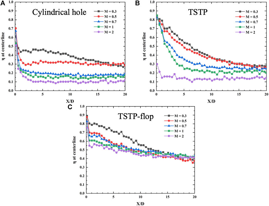
FIGURE 8. Film cooling effectiveness along with the streamline direction for different blow ratios. (A) Cylindrical hole, (B) TSTP, (C) TSTP-flop.
The spanwise-averaged cooling effectiveness is shown in Figure 9. The film cooling effectiveness was averaged along the spanwise direction at the given multiple positions of X/D from the thermographic data in Figure 7. Consequently, the film coverage between the film cooling holes can be evaluated. For the cylindrical hole and TSTP, a considerable decrease in cooling effectiveness was observed with an increase in the blowing ratio, as shown in Figures 9A,B. The conventional cylindrical hole showed low cooling performance due to the increased jet penetration with increased blowing ratio. Although TSTP alleviated the jet penetration, however, the trends remained same with high blowing ratio as seen in Figure 9B. Meanwhile, the TSTP-flop presented the highest cooling effectiveness owing to the largest covered cooling area, as shown in Figure 9C. The direction of cooling flow was against the main flow, so that the jet penetration was suppressed by the main flow. In addition, the film flow structure was stable at the downstream. The graphs indicate that the TSTP-flop also extended the cooling coverage regardless of the blowing ratio. In addition, the film-cooling extension was considerably higher than that of the cylindrical hole and TSTP. Consequently, the applied TSTP-flop exhibited the best cooling performance.
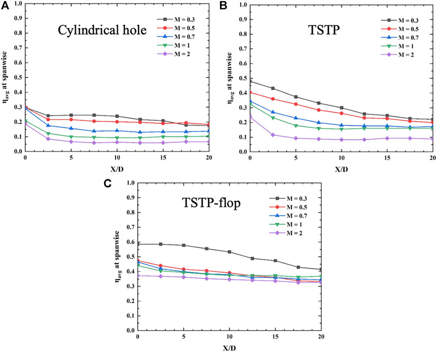
FIGURE 9. Film cooling effectiveness along with the spanwise direction for different blowing ratios. (A) Cylindrical hole, (B) TSTP, (C) TSTP-flop.
3.3 Overall cooling performance
Figure 10 presents the resulting average cooling effectiveness over the entire cooling area. For the cylindrical hole, the resulting averaged film cooling effectiveness was 0.22 at M = 0.3 and decreased to 0.07 at M = 2.0. This is because of the strong detachment of the film flow, as shown in Figures 5, 6. Although TSTP showed a similar trend, however, the decrease of averaged film cooling effectiveness was from 0.32 to 0.11 when the blowing ratio was from M = 0.3 and 2.0. The suggested TSTP-flop showed a significant improvement in the averaged film cooling effectiveness. The values ranged from 0.52 to 0.34, where the blowing ratio varied from M = 0.3 to 2.0. Moreover, it can be observed that the decrease in the average film cooling effectiveness also improved as the blowing ratio increased. The effect of TSTP-flop significantly enhanced the overall film cooling effectiveness by successfully suppressing the upward momentum of the cooling flow and retaining the downward film flow.
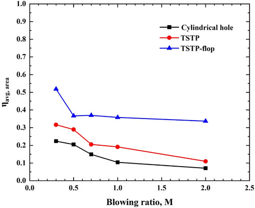
FIGURE 10. Area-averaged film cooling effectiveness against blowing ratio for the different cooling hole configurations.
The discharge parameters composed of discharge coefficient, mass flow rate, area, and pressure of film cooling hole. With these parameters, the required film cooling flow can be estimated and compared between existing cylindrical hole shape and suggest hole shape. The discharge coefficient was evaluated using the measured total and static pressures, as described in Eq. 3. As shown in Figure 11, the discharge coefficient (Cd) was plotted against the Reynolds number, which was calculated from the cooling hole diameter and velocity. The discharge coefficient increased with respect to the Reynolds number. When the Re number was 4,004 (M = 1.0), the discharge coefficient was 0.64 for typical film cooling configuration (cylindrical shape). Meanwhile, at the same blowing ratio the discharge coefficients decreased to 0.62 and 0.58 for TSTP and TSTP-flop, respectively. This tendency persisted for the other blowing ration. With this, it can be found that the TSTP and TSTP-flop induced more discharge resistances of 3.1 and 9.4% for the two cases than typical film cooling configuration. The higher film cooling velocity (Reynolds number at the cooling flow inlet) caused stronger momentum, resulting in a higher discharge coefficient (Liu et al., 2020). Meanwhile, the application of TSTP and TSTP-flop decreased the discharge coefficient compared with the cylindrical hole. As described in Eq. 3, a small discharge coefficient requires a higher total cooling flow pressure at a given mass flow rate of the cooling flow. As a result, when TSTP and TSTP-flop were applied, partial blockage induced an increased total pressure. The smallest discharge coefficient of the TSTP-flop originated from the most effective suppression of film cooling flow detachment, as shown in Figures 5, 6 of the flow visualizations. Note that the TSTP-flop can significantly enhance film cooling effectiveness; however, it also requires additional pressure for the given blowing ratios.
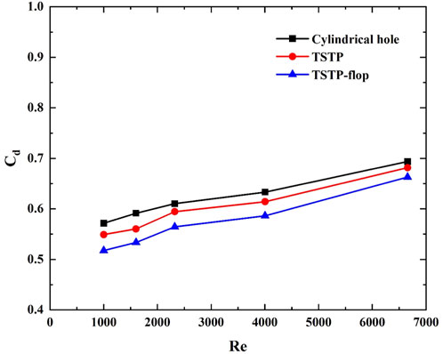
FIGURE 11. Comparison of discharge coefficient for the different cooling hole configurations.
4 Conclusion
The cylindrical hole film cooling for gas turbine applications was experimentally investigated by applying an additional TSTP and TSTP-flop. From the flow visualizations, significant flow detachments were observed to induce vortex pairs immediately after the cooling holes. These phenomena were mitigated by applying the TSTP and TSTP-flop. The cross-sectional and in-plane flow visualization revealed changes in the film cooling flow distribution, which resulted in enhanced cooling effectiveness.
The TSTP and TSTP-flop enhanced the overall cooling effectiveness of up to 0.19 and 0.36 at a blowing ratio of 1.0, respectively. The TSTP-flop most effectively evolved the film cooling flow by suppressing the flow detachment at the hole and retaining the film flow without significant dispersion at the distant downstream. As a results, 242.7% improvement in film cooling effectiveness can be achieved by using TSTP-flop with 8% increase of discharge coefficient than conventional cylindrical hole. The discharge coefficient indicated an additional flow pressure to provide the given blowing ratios when applying the TSTP-flop. Although this is a disadvantage of applying the TSTP-flop, the proposed technique can satisfy the required cooling performance of advanced gas turbine applications with high inlet temperatures. The future scope of this work is to develop the TSTP-flop design with considering manufacturing technologies in gas turbine applications.
Data availability statement
The original contributions presented in the study are included in the article/supplementary material, further inquiries can be directed to the corresponding author.
Author contributions
JMC conducted experimentation and writing. JHC, HK, and HJ conducted experimental setup. HP contributed to fund acquisition, leading the experiments and analysing the results. HP also revised the writing.
Funding
This work was supported by the Korea Institute of Energy Technology Evaluation and Planning (KETEP) grant funded by the Korean government (MOTIE, 20214000000480, Development of R&D Engineers for Combined Cycle Power Plant Technologies).
Conflict of interest
The authors declare that the research was conducted in the absence of any commercial or financial relationships that could be construed as a potential conflict of interest.
Publisher’s note
All claims expressed in this article are solely those of the authors and do not necessarily represent those of their affiliated organizations, or those of the publisher, the editors and the reviewers. Any product that may be evaluated in this article, or claim that may be made by its manufacturer, is not guaranteed or endorsed by the publisher.
References
Al-Zurfi, N., Turan, A., Nasser, A., and Alhusseny, A. (2019). A numerical study of anti-vortex film cooling holes designs in a 1-1/2 turbine stage using LES. Propuls. Power Res. 8, 275–299. doi:10.1016/j.jppr.2019.10.001
An, B. T., Liu, J. J., and Zhou, S. J. (2017). Geometrical parameter effects on film-cooling effectiveness of rectangular diffusion holes. J. Turbomach. 139, 081010. doi:10.1115/1.4036007
Blanchard, J. N., Brunet, Y., and Merlen, A. (1999). Influence of a counter-rotating vortex pair on the stability of a jet in a cross flow: An experimental study by flow visualizations. Exp. Fluids 26, 63–74. doi:10.1007/s003480050265
Bunker, R. S. (2000). Effect of partial coating blockage on film cooling effectiveness. ASME Turbo Expo. Report No: 2000-GT-0244.
Fawzy, H., Zheng, Q., Jiang, Y., Lin, A., Ahmad, N., Malik, A., et al. (2020). Study of utilizing double lateral sub holes at different spanwise angles on blade film cooling effectiveness. Int. Commun. Heat Mass Transf. 117, 104728. doi:10.1016/j.icheatmasstransfer.2020.104728
Fric, T. F., and Roshko, A. (1994). Vortical structure in the wake of a transverse jet. J. Fluid Mech. 279, 1–47. doi:10.1017/s0022112094003800
Fu, Z., Zhu, H., Liu, C., Wei, J., and Zhang, B. (2018). Investigation of the influence of inclination angle and diffusion angle on the film cooling performance of chevron-shaped hole. J. Therm. Sci. 27, 580–591. doi:10.1007/s11630-018-1070-8
Goldstein, R. J., Eckert, E. R. G., Eriksen, V. L., and Ramsey, J. W. (1970). Film cooling following injection through an inclined circular tube. Isr. J. Technol. 8, 145–154.
Huang, K., Zhang, J., Tan, X., and Shan, Y. (2018). Experimental study on film cooling performance of imperfect holes. Chin. J. Aeronautics 31, 1215–1221. doi:10.1016/j.cja.2018.04.001
Huang, Y., Zhang, J., and Wang, C. (2020). Multi-objective optimization of round-to-slot film cooling holes on a flat surface. Aerosp. Sci. Technol. 100, 105737. doi:10.1016/j.ast.2020.105737
Jovanovic, M. B., De Lange, H. C., and Van Steenhoven, A. A. (2005). Influence of laser drilling imperfection on film cooling performance. ASME Turbo Expo. Report No: GT2005-68251.
Kelso, R. M., Lim, T. T., and Perry, A. E. (1996). An experimental study of round jets in cross-flow. J. Fluid Mech. 206, 111–144. doi:10.1017/s0022112096001255
Khajehhasani, S., and Jubran, B. A. (2016). A numerical evaluation of the performance of film cooling from a circular exit shaped hole with sister holes influence. Heat. Transf. Eng. 37, 183–197. doi:10.1080/01457632.2015.1044415
Khalatov, A., Shi-Ju, E., Wang, D., and Borisov, I. (2020). Film cooling evaluation of a single array of triangular craters. Int. J. Heat Mass Transf. 159, 120055. doi:10.1016/j.ijheatmasstransfer.2020.120055
Kim, M., Shin, D. H., Kim, J. S., Lee, B. J., and Lee, J. (2021). Experimental investigation of effusion and transpiration air cooling for single turbine blade. Appl. Therm. Eng. 182, 116156. doi:10.1016/j.applthermaleng.2020.116156
Liu, C., Xie, G., Zhu, H., and Luo, J. (2020). Effect of internal coolant crossflow on the film cooling performance of converging slot hole. Int. J. Therm. Sci. 154, 106385. doi:10.1016/j.ijthermalsci.2020.106385
McClintic, J. W., Anderson, J. B., Bogard, D. G., Dyson, T. E., and Webster, Z. D. (2018a). Effect of internal crossflow velocity on film cooling effectiveness—Part I: Axial shaped holes. J. Turbomach. 140, 011003. doi:10.1115/1.4037997
McClintic, J. W., Anderson, J. B., Bogard, D. G., Dyson, T. E., and Webster, Z. D. (2018b). Effect of internal crossflow velocity on film cooling effectiveness—Part II: Compound angle shaped holes. J. Turbomach. 140, 011004. doi:10.1115/1.4037998
Nondy, J., and Gogoi, T. K. (2020). Comparative performance analysis of four different combined power and cooling systems integrated with a tipping gas turbine plant. Energy Convers. Manag. 223, 113242.
Pedersen, D. R., Eckert, E. R. G., and Goldstein, R. J. (1977). Film cooling with large density differences between the mainstream and the secondary fluid measured by the heat-mass transfer analogy. J. Heat Transf. 99, 620–627. doi:10.1115/1.3450752
Ramesh, S., Ramirez, D. G., Ekkad, S. V., and Alvin, M. A. (2016). Analysis of film cooling performance of advanced tripod hole geometries with and without manufacturing features. Int. J. Heat Mass Transf. 94, 9–19. doi:10.1016/j.ijheatmasstransfer.2015.11.033
Schmidt, D. L., Sen, B., and Bogard, D. G. (1996). Film cooling with compound angle holes: Adiabatic effectiveness. J. Turbomach. 118, 807–813. doi:10.1115/1.2840938
Wang, J., Zhao, Z., Tian, L., Ren, Z., and Sunden, B. (2021). Effects of hole configuration on film cooling effectiveness and particle deposition on curved surfaces in gas turbines. Appl. Therm. Eng. 190, 116861. doi:10.1016/j.applthermaleng.2021.116861
Waye, S. K., and Bogard, D. G. (2007). High-resolution film cooling effectiveness measurements of axial holes embedded in a transverse trench with various trench configurations. J. Turbomach. 129, 294–302. doi:10.1115/1.2464141
Yu, Z., Li, C., An, B., Liu, J., and Xu, G. (2020). Experimental investigation of film cooling effectiveness on a gas turbine blade pressure surface with diffusion slot holes. Appl. Therm. Eng. 168, 114851. doi:10.1016/j.applthermaleng.2019.114851
Zhang, J., Zhang, S., Wang, C., and Tan, X. (2020). Recent advances in film cooling enhancement: A review. Chin. J. Aeronautics 33, 1119–1136.
Keywords: gas turbine, film cooling, flow visualization, triangular-shaped thin plate, cooling effectiveness, blowing ratio
Citation: Choi J, Choi J, Kwon H, Jang H and Park H (2022) Experimental investigation of the film cooling performance by triangular-shaped thin plates on inclined cylindrical holes. Front. Energy Res. 10:981275. doi: 10.3389/fenrg.2022.981275
Received: 29 June 2022; Accepted: 07 September 2022;
Published: 26 September 2022.
Edited by:
Yilin Fan, UMR6607 Laboratoire de Thermique et Énergie de Nantes (LTeN), FranceReviewed by:
Seyed Soheil Mousavi Ajarostaghi, Babol Noshirvani University of Technology, IranMayank Modak, Seoul National University, South Korea
Copyright © 2022 Choi, Choi, Kwon, Jang and Park. This is an open-access article distributed under the terms of the Creative Commons Attribution License (CC BY). The use, distribution or reproduction in other forums is permitted, provided the original author(s) and the copyright owner(s) are credited and that the original publication in this journal is cited, in accordance with accepted academic practice. No use, distribution or reproduction is permitted which does not comply with these terms.
*Correspondence: Heesung Park, aGVlc3VuZ3BhcmtAY2hhbmd3b24uYWMua3I=