 B Karthikeyan1
 K Sundararaju2
 R Palanisamy3
 R Manivasagam4
 Ismail Hossain5
 Mohit Bajaj6
 Mokhtar Shouran7
 Bdereddin Abdul samad7*
 Salah Kamel8
- 1Department of Electrical and Electronics Engineering, K. Ramakrishnan College of Technology, Trichy, India
- 2Department of Electrical and Electronics Engineering, M. Kumarasamy College of Engineering, Karur, India
- 3Department of Electrical and Electronics Engineering, SRM Institute of Science and Technology, Chennai, India
- 4Department of Electrical and Electronics Engineering, K. Ramakrishnan College of Engineering, Trichy, India
- 5School of Natural Sciences and Mathematics, Ural Federal University, Yekaterinburg, Russia
- 6Department of Electrical Engineering, Graphic Era (Deemed to be University), Dehradun, India
- 7School of Engineering, Cardiff University, Cardiff, United Kingdom
- 8Electrical Engineering Department, Faculty of Engineering, Aswan University, Aswan, Egypt
There is a need to design DC-DC converters capable of handling high voltages and that employ single-stage conversion to integrate renewable energy resources, such as solar photovoltaic cells and fuel cells, for electric vehicle applications. This paper elucidates the design and analysis of a dual input single output non-isolated Cuk-derived converter with a high step-up ratio. The proposed converter can effectively handle two different energy resources that have different electrical characteristics. It makes use of one common inductor between the dual input port, which reduces the passive components and the circuit volume required. The maximum efficiency that can be achieved by this converter is 95.72%, with two main switches and one diode in the circuit. This study involved a detailed analysis of the proposed converter in continuous current operation mode. A continuous current with reduced ripple in the output improves a fuel cell’s operating life-span. The efficacy of the proposed converter is verified through simulation and validated by constructing a 200 W, real-time, scaled-down prototype model.
1 Introduction
The use of fossil fuels is undergoing a slow reduction, due to their finite nature and negative effects on the environment. Renewable sources of energy have the potential to meet demand without any adverse effects on the environment. Hence, it is an obvious choice to make use of renewable energy resources for power generation in grid-connected applications and for standalone automotive applications. Although there is a variety of renewable energy resources available, solar photovoltaic (PV) and fuel cell sources possess advantages such as being portable and scalable in size. These advantages mean that these sources can be used for hybrid-source electric vehicle (HEV) applications. There is a crucial role for modern power electronics converters to address the issues while interconnecting with standalone automotive applications when it fed from renewable energy sources. In the remainder of this section, we review the extensive work carried by pioneering researchers in this field.
A multi-port non-isolated DC-DC converter was proposed by Suresh et al. (2021), which was capable of handling multiple energy sources. Their findings made it clear that the proposed converter could perform step-up and step-down operations according to the load requirement, with an impressive voltage-conversion ratio and good power efficiency. A DC-DC converter topology for electric vehicle chargers was designed by Lee et al. (2019), which could achieve a power conversion efficiency of 97% and had high-speed charging capability. It had few passive components, resulting in a small circuit volume while achieving a high degree of energy density. A 20-kW experimental setup demonstrated the efficacy of their proposed converter.
For lithium-ion (Li-ion) batteries, super-capacitor powered HEV applications, a family of DC-DC converters were used by different researchers in the past. A review of various DC-DC converters for HEV applications, conducted by Mamouri et al. (2020), also stressed the importance of DC-DC converters for HEV applications. A multiple input port DC-DC converter with bidirectional capabilities, for use in HEV applications, was proposed by Akar et al. (2015). A simulation study of the battery and an ultracapacitor source demonstrated the good performance of the proposed converter. The experimental setup these researchers built could achieve an overall conversion efficiency of 93%, with minimum use of passive components.
For a wide range of input voltages, a powerful DC-DC converter design was essential in such a way it must be handling the hybrid energy sources. Taking this into consideration, a DC-DC converter was proposed by Hu et al. (2018). The proposed system was capable of handling two renewable sources, such as solar PV cells and wind energy, in complementary mode. The experimental arrangement demonstrated the accuracy of the modulation strategy in such a way that a smooth transition of the mode of operation occurred. Dusmez et al. (2015) designed a single input and multiple output DC-DC converter with zero voltage switching. Each cell in the proposed topology comprised a resonant tank circuit which made the bulky circuit volume. The maximum power conversion efficiency achieved by this converter was almost 96% under a high-load current with reduced Duty cycle due to the use of soft switching capacity.
A single-input with dual-output DC-DC converter with buck/boost capability was proposed by Shang and Wang (2016). The proposed converter yielded a high voltage gain during the boost operation mode and achieved good steady state and dynamic characteristics during the buck operation mode. The switching losses were considerably reduced, resulting in improved efficiency. Karthikeyan et al. (2021) proposed a DC-DC converter topology dedicated for polymer exchange membrane (PEM) fuel cell applications, with switching pulses that were controlled by a fuzzy-based MPPT controller under variable temperature conditions. The proposed converter switches were triggered under zero voltage transition at medium to high power ranges. The simulation study and experimental results revealed the converter’s capacity for handling fuel cell sources under variable temperature conditions.
It was difficult to handle much number of sources with individual DC-DC converters. Hence it could accomplish with the usage of Multiple-Input port and Multiple-Output port DC-DC converter designed by Ahmed et al. (2018). The research challenges faced by them during the analysis carried were also briefed by them. A detailed review of multiple-input and multiple-output DC-DC converters was carried out by Dhanajaya et al. (2021). The converters considered in the review were dedicated for grid-connected applications and HEV applications. The detailed review revealed the importance of multiple-input and multiple-output DC-DC converters.
A DC-DC converter was proposed by Gupta et al. (2020), with combined features of both Cuk converters and buck-boost converters, for renewable energy source integration with DC micro-grid applications. The main advantage claimed in their work was minimum number stages without the aid of voltage multiplier cells and transformers. A single input and dual output solar powered DC-DC converter was proposed by Akhil Raj and Arya (2021), along with a modified P&O MPPT controller. The performances of the proposed converter were analyzed using the MATLAB Simulink tool and validated with the real time emulator, OP5142. A DC-DC converter with bidirectional capabilities for more than one source application was proposed by Yi et al. (2022). The proposed converter topology consisted of a minimum number of components and was able to charge/discharge the battery with minimum switching losses and improved peak efficiency.
A three-port DC-DC converter was proposed by Aljarajreh et al., (2021), in which two converters were bidirectional and one was unidirectional. In that study, generalized topological study to derive the three port converters among which two explicit bidirectional converters. A three-port DC-DC converter for simultaneously handling solar PV and battery sources was proposed by Khoramikia et al. (2018). The proposed converter incorporated a maximum power tracking controller for the solar PV system and a charging and discharging controller for the battery back-up. The voltage conversion gain was high enough to meet the demand by reducing the current ripples in the inductor and switching losses, thereby increasing the conversion efficiency.
2 Hybrid energy sources
2.1 Solar PV modeling
Solar energy is the most popular renewable source of energy in use because of its various features, such as silent operation, being portable and scalable in size, quick start up etc. The conventional modeling of solar PV systems consists of a current source and a diode connected in anti-parallel across it. The shunt resistance is extremely high in the parallel path and can be neglected in the modeling. The solar PV cells are connected in series and parallel to improve voltage and current levels, respectively. A solar array is made up of multiple PV cells connected in series and parallel. The parallel connection is responsible for increasing the current in the array, whereas the series connection is responsible for increasing the voltage of the module. The leakage current causes series resistance, whereas the impediment in the path of electron transport from the n to the p junction causes parallel resistance. Figure.1A illustrates the equivalent circuit for PV modeling.
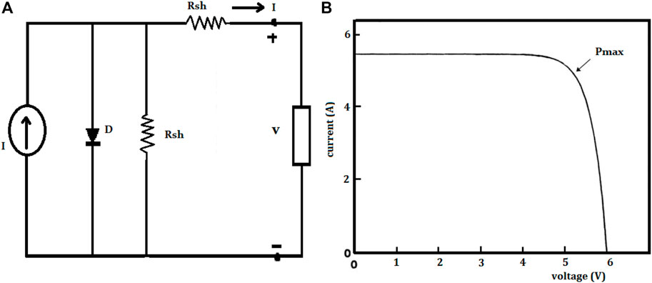
FIGURE 1. PV modeling (A) equ. circuit of a PV array (B) I-V characteristics of PV panel.
The output current equations used to model a PV array are:
Where Ig is the diode’s reverse saturation current, n is the electron charge, Vk is the voltage across the diode, p is the Boltzmann constant, and T is the junction temperature. From Equations 1 and 2 we can obtain:
We could utilize two diode models to accurately model the solar panel, but our project’s topic of study was confined to the single diode model. Furthermore, the shunt resistance is very high and thus was overlooked during our research. Figure 1B demonstrates the I-V parameters of a typical solar cell.
2.2 Polymer exchange membrane fuel cell modeling
A fuel cell is an electrochemical device, in which chemical energy is directly converted into electrical energy. Fuel cells can be classified into many types depending on the material and nature of electrolyte is taken in the reformer. Among the types of fuel cells, PEM fuel cells play a vital role because of their major advantages, such as being scalable in size, having moderate power conversion efficiency, having a low operating temperature etc. Initially, the hydrogen-rich fuel is reformed in the reformer to produce pure hydrogen. This is oxidized into protons and electrons as indicated in the Figure 2. A proton is transferred from electrode “A” to another electrode “B” through the PEM fuel cell, which strictly resists the electron flow. The electron will move from “A” to “B” through the external circuit, which causes an electric current. Oxygen-rich air is supplied at electrode “C” to enable reduction. The overall chemical reaction that takes place inside the fuel cell is shown in Figure 2.
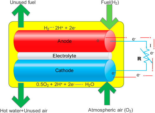
FIGURE 2. Polymer exchange membrane fuel cell.
The terminal voltage of a PEM fuel cell can be written as:
According to Nernst’s equation:
where T is the operating cell temperature,
where R is the total resistance of both the membrane and the contact and is expressed in ohms.
where R is the universal gas constant, F is Faraday’s constant, I is the fuel cell current, and imax is the fuel cell current.
From Equations 1–5, it can be inferred that the operating voltage of PEM fuel cells depends on their operating parameters, such as cell temperature, hydrogen partial pressure, oxygen partial pressure, membrane water content, oxygen concentration etc.
3 The proposed non-isolated DC-DC converter
The proposed non-isolated DC-DC converter consists of two different renewable energy sources, such as a solar PV system and a PEM fuel cell. It has two main switches (S1, S2) and two auxiliary switches, as shown in Figure 3. The filter inductors (L1, L2) remove current ripples and store electrical energy when the main switches are in the ON condition. The auxiliary switches are used to isolate either of the sources from the circuit if the other source is capable of delivering the energy to the load. There are is output inductor and capacitor combination (L3-C3) to supply the load when main auxiliary diode D1 is in ON condition. To check the efficiency of the converter, a variable resistive load (RL) can be connected.
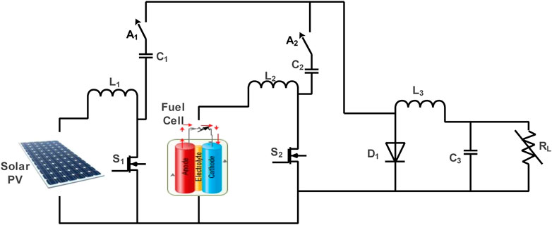
FIGURE 3. Proposed dual input single output non-isolated DC-DC converter.
3.1 Mode of operation
State 1:
In state 1, the auxiliary switch A1 is closed, whereas the auxiliary switch A2 is open, to ensure the solar PV is supplying the load. When switch S1 is in the ON condition, the inductor L1 is able to store energy. The diode D1 comes into action when the main switch S1 is in the OFF condition. The direction of the current during state 1 is shown in Figure 4 (state 1), and its steady state equations are derived as shown below.
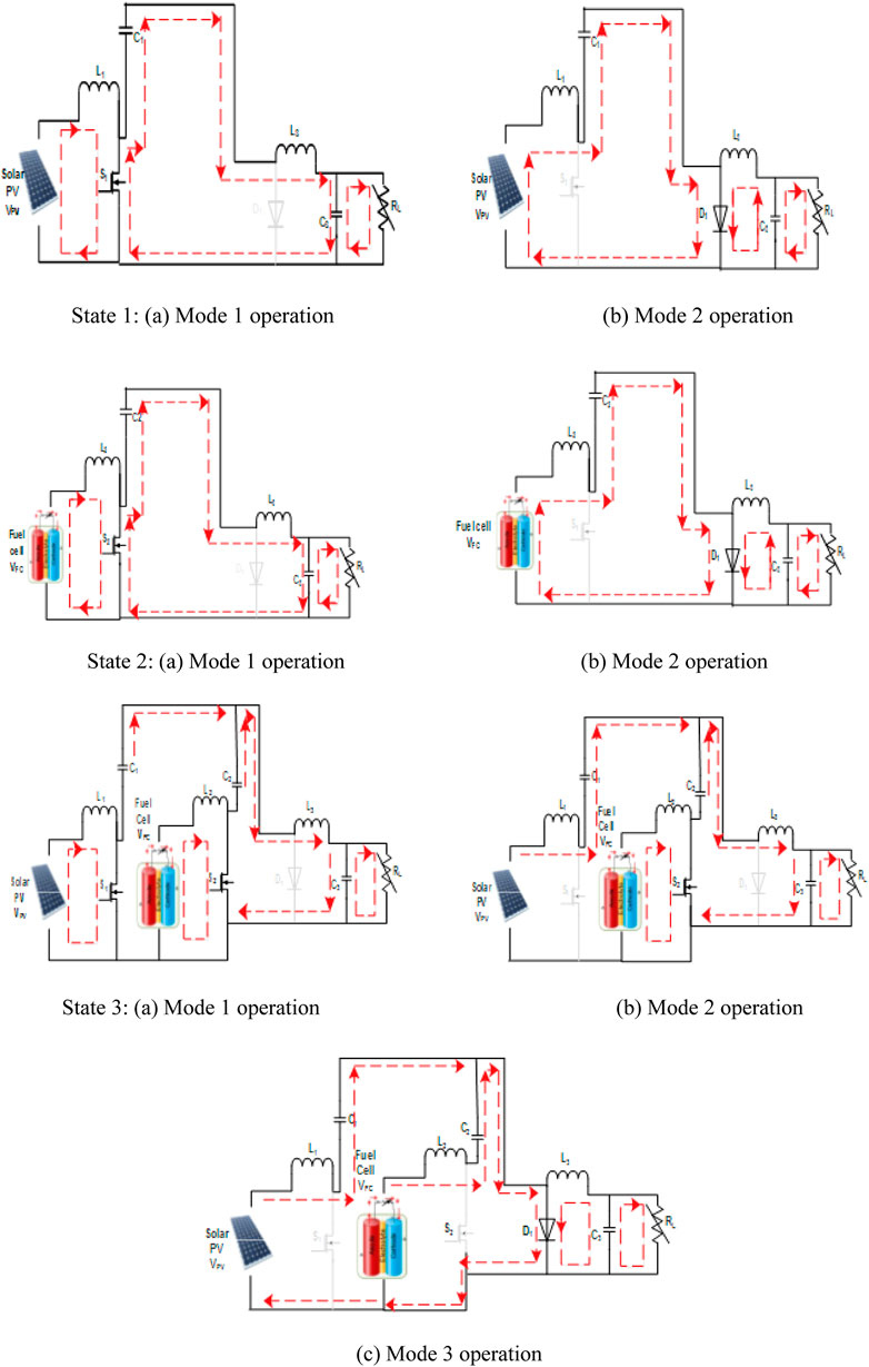
FIGURE 4. Mode of operation of the proposed DC-DC converter. State 1: (A) mode 1 operation (B) mode 2 operation. State 2: (A) mode 1 operation (B) mode 2 operation. State 3: (A) mode 1 operation (B) mode 2 operation (C) mode 3 operation.
State 2:
The auxiliary switch A2 is closed to become connected with the fuel cell source, and auxiliary switch A1 is opened to disconnect the solar PV source, as shown in Figure 4 (state 2). The switch S2 is turned on, during which time the inductor L2 is being charged. The inductor is intended to release its stored energy when the main switch S2 is in the OFF condition and D1 is in the ON condition. The steady state equations of state 2 are derived as follows.
State 3:
When any one of the sources is not able to supply the load, it is necessary to use two sources simultaneously. In mode 1, both switches (S1, S2) are turned on and both inductors (L1, L2) are being charged. The pre-charged capacitors (C1, C2) release energy to the load through the load-side inductor L3.
During mode 2, the switch S1 is kept in the OFF condition, and the switch S2 is in the ON condition, which makes the inductor current increase continuously. The energy stored in the inductor L1 is released to the capacitor C1 and the load-side inductor L3, as shown in Figure 4 (state 3).
During mode 3, both switches are in the OFF condition, which makes the diode across the load to be in the ON condition. The solar PV voltage and stored energy in the inductor L1 are released through the capacitor C1, while the fuel cell voltage and stored energy in the inductor L2 are released through the capacitor C2, as shown in Figure 5. The load is free-wheeled through the diode D1.
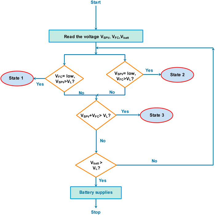
FIGURE 5. Flowchart for the control technique.
4 Control strategies
The operating mode of the proposed double input single output non-isolated converter is shown in the flow diagram in Figure 5. Initially, the operating voltage of both the renewable energy sources and the battery are read by the controller. If the operating voltage of the solar PV system is higher than the demand, and the fuel cell is unable to meet the demand, then the solar PV is meant to deliver the load and the fuel cell is non-operative, and vice versa. If neither source is able to meet the demand individually but both sources combined are able to supply the load, then both sources are operated simultaneously. If both sources combined are unable to meet the demand, it is important to have a back-up source in place and ready to use.
4.1 Particle swarm optimization (PSO)-based MPPT controller
It is essential to incorporate a maximum power tracking controller to trace the optimum power from solar panels and fuel cells under variable operating conditions. Modeling of solar PV systems has shown that the output voltage is influenced by many parameters, with solar irradiance being the most significant factor. Similarly, the fuel cell output voltage is influenced by many operating conditions, such as hydrogen pressure, membrane water content, concentration of the electrolyte, and temperature. Among these, temperature is considered to be the most significant. A common PSO algorithm-based maximum power tracking controller is designed in such a way that it ensures maximum power extraction from solar panels when solar irradiance varies and maximum power extraction from fuel cells when the operating temperature varies.
PSO is an evolutionary algorithm that imitates birds flocking while traveling from one place to another. It finds global maxima rather than local maxima. Each bird in a flock tries to find the optimum position (
A previously visited position (
The particles are updated by multiplying the weight with the corresponding velocity, as shown below:
Where i indicates the flock size, ai represents the acceleration constant, and ci represents random variables. The weight updating is performed in consecutive iterations, as follows:
4.2 Voltage conversion ratio
The total output voltage can be expressed as:
From Equations 15 and 16, the total output voltage can be expressed as:
Figure 6 shows the voltage conversion ratio for the proposed system. Assuming an equal voltage is supplied by each of the renewable energy sources,
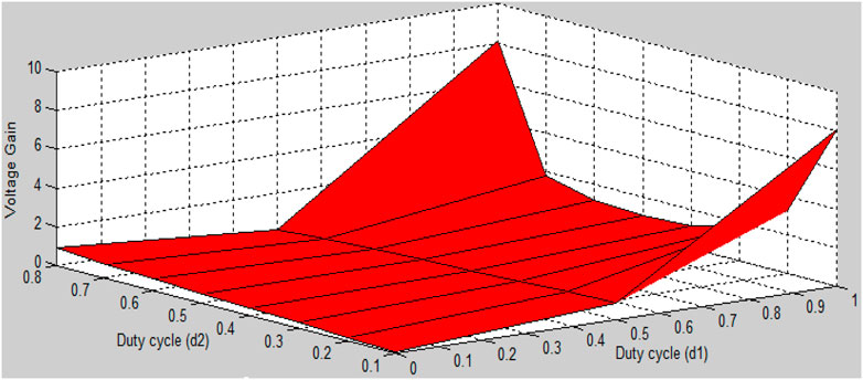
FIGURE 6. Voltage conversion ratio.
5 Small signal modeling
The proposed converter is excited from two different renewable energy resources and hence state space analysis is the obvious for small signal modeling (Iqbal and Maswood, 2020; Iqbal and Maswood, 2021). The transfer function of the n-dimensional system is given by:
where C and R represent the output and input of a converter, respectively, and A, B, C, and D represent a system matrix of (nxn), input matrix, output matrix, and transmission matrix, respectively. The generalized state model of any system can be described as follows:
The selection of state variables and output variables is arbitrary and need not be unique. They can be chosen as follows:
The state model of the proposed converter can be formulated by referring to Equations 9 to 21, as follows:
5.1 Proportional integral (PI) controller tuning
To obtain a good steady-state performance, it is necessary to optimize the PI controller parameters. There are two parameters that must be calculated to achieve a good steady-state performance. These are the delay time and the time constant, the values of which must be optimized. The value of the delay time (
where
6 Simulation results and discussion
The simulation analysis of the proposed converter for handling both solar PV and fuel cells was carried out using the MATLAB/R2022a Simulink environment. The components used in the simulation analysis and hardware setup are listed in Table 1. The following section elucidates the simulation analysis with solar PV and fuel cell sources, and both sources simultaneously meet the demand.
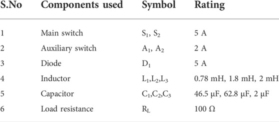
TABLE 1. Components used in the proposed converter.
6.1 Steady state simulation results
It is important to analyze the performance of the system with a fixed DC voltage under steady state conditions before it is supplied by two different renewable energy resources, each having different electrical characteristics. The duty cycles for the switches are maintained as d1 = 0.45 and d2 = 0.68, as shown in Figure 7A. The corresponding inductor currents, IL1, IL2, and the capacitor voltages, VC1 and VC2, are shown in Figure 7B–E, which shows the variation in capacitor and inductor voltages to boost the applied DC input voltage.
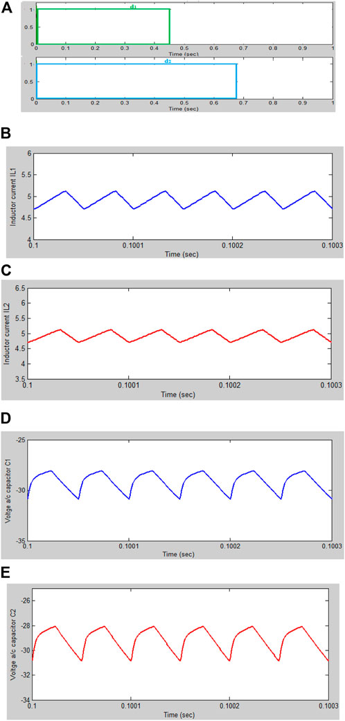
FIGURE 7. The steady state performance of DISO-NI converter. (A) Switching pulse to switches S1,S2. (B) Inductor L1 current. (C) Inductor L2 current. (D) Voltage across Capacitor C1. (E) Voltage across Capacitor C2.
Case 1: The solar PV can meet the demand
To analyze the performance of the proposed converter with a solar PV source, a 250 W, 40 V source is considered. In case 1), the solar PV alone is supplying the load. The input voltage received from the solar PV is 40 V. It is stepped-up to 130 V, and the output current obtained under this case is 2.32 A when the duty cycle is kept at d1 = 76%. The solar irradiance is varied as follows: 1,000 w/m2 for 0–1 s, 500 w/m2 for 1–2 s, and 1,500 w/m2 for 2–3 s. The maximum power extracted from the solar panel with a P&O controller and a PSO controller is shown in Figure 8. The PSO controller outperformed the P&O controller in terms of maximum power and steady state performance.
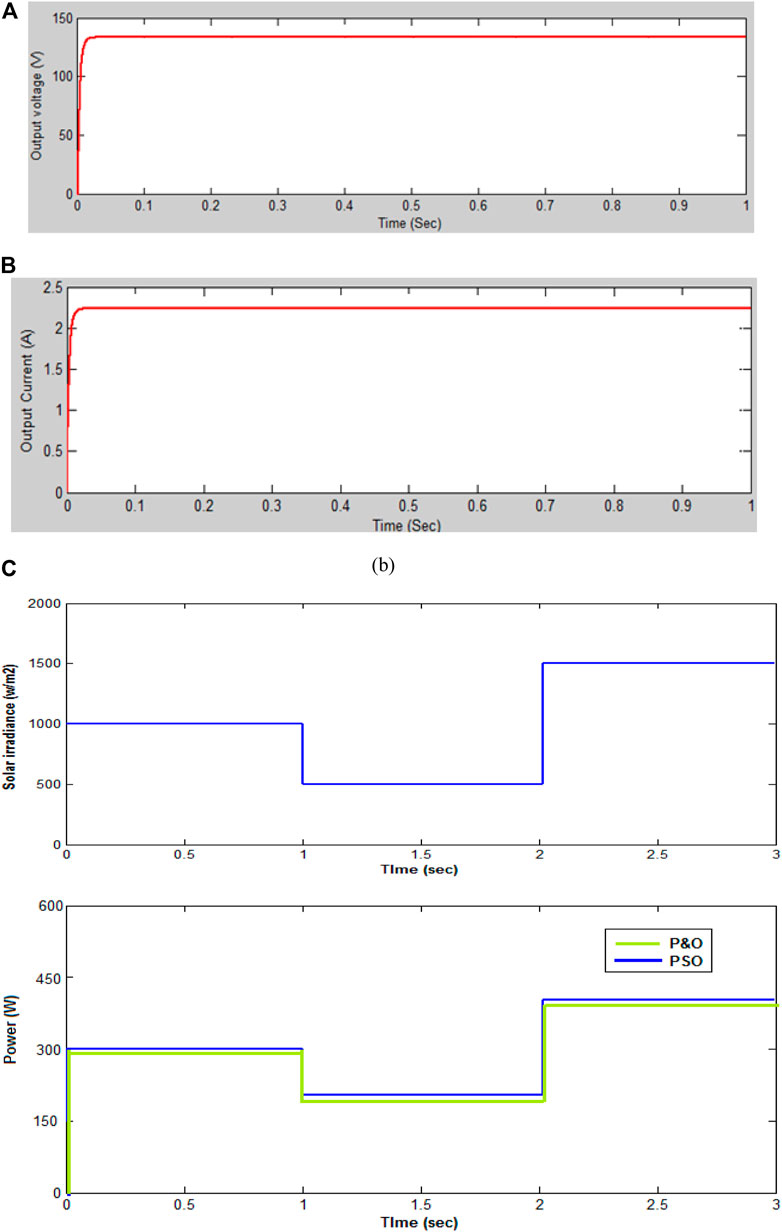
FIGURE 8. (A) The output voltage of the dual input single output non-isolated converter fed by solar PV. (B) The output current of the dual input single output non-isolated converter fed by solar PV (C). The maximum power extracted from a solar PV using a PSO and a conventional P&O controller.
To check the performance of the proposed converter with a PEM fuel cell source, a 6 kW, 45 V PEM fuel cell is considered, whose I-V and I-P are shown in Figure 9. In case 2), the solar PV is unable to supply the load so the fuel cell comes into action to supply the load. The open circuit voltage obtained was 45 V, as indicated in Figure 9. This increased to 146.25 V and the corresponding steady state current was 2.53 A when the duty cycle d2 = 76.47%, as shown in Figure 10. To check the performance of the PSO-based MPPT controller, the operating temperature of the fuel cell was varied as follows: 328 K for 0–0.3 s, 298 K for 0.3–0.6 s, and 358 K for 0.6–0.9 s. The corresponding power variation is shown in figure. The power extracted from a PEM fuel cell with a PSO controller was greater than the power extracted with a conventional P&O controller.
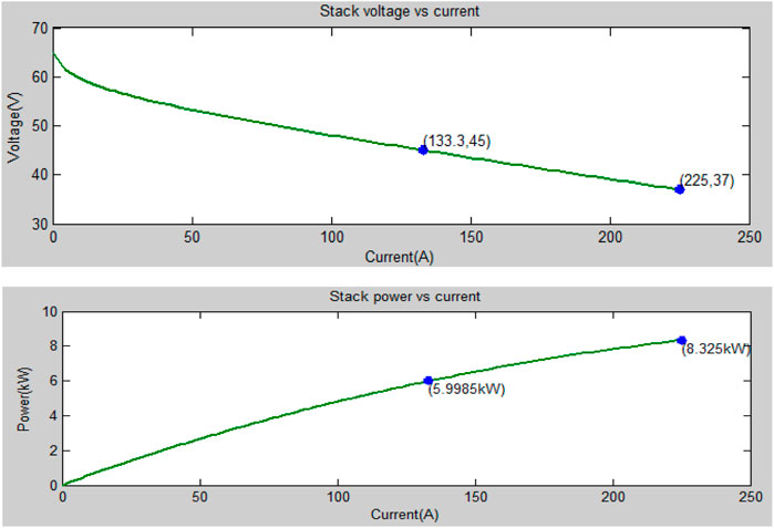
FIGURE 9. Characteristics of a 6-kW PEM fuel cell.
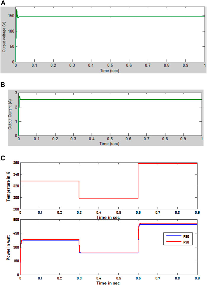
FIGURE 10. (A) The output voltage of the dual input single output non-isolated converter fed from a fuel cell (B) The output current of the dual input single output non-isolated converter fed from a fuel cell (C) The maximum power extracted from a PEM fuel cell using a PSO and a conventional P&O controller.
Case 3: The solar PV and fuel cell together are needed to meet the demand
Sometimes both sources are needed to meet the load if an individual source alone is unable to meet the load requirements. As a typical case, the solar PV supplies 30 V and the fuel cell supplies 35 V in case 3. The total voltage is increased to 211.25 V under steady state operating conditions when the duty cycle is kept at d1 = 50% and d2 = 60%, as shown in Figure 11.
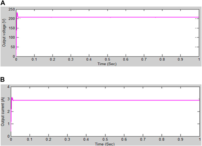
FIGURE 11. (A) Output voltage of DISO-NI converter fed from Solar PV system and PEM fuel cell. (B) Output current of DISO-NI converter fed from Solar PV system and PEM fuel cell.
7 Experimental results and discussion
An experimental setup was designed and used to test a dual input single output non-isolated Cuk-derived converter with a high step-up ratio, which provides better performance compared with other, conventional systems. This experimental setup included a PV system, a fuel cell, a non-isolated DC-DC converter, capacitors, and an inductor for boosting the voltage levels. The switching pulses are generated for a non-isolated DC converter using a PWM generator, which is shown in Figure 12.
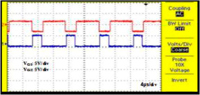
FIGURE 12. Switching pulses for the isolated DC-DC converter.
The overall converter losses were calculated to be 8.56%, which comprised the following losses: main switch loss, auxiliary switch loss, diode loss, inductor loss, capacitor loss, and other practical losses. The main and auxiliary switch losses included both switching and conduction losses.
The non-isolated DC-DC converter output voltage for the experimental system is shown in Figure 13 Figure 13A shows the output voltage for the PV system operating as the input source, with a voltage of 128.5 V; similarly, Figure 13B shows the output voltage for the fuel cell operating as the input source, with a voltage of 136.5 V; while Figure 13C shows the output voltage for the PV system and the fuel cell operating together as the input source, with a voltage of 207 V. Figure 13D–G show the current flowing through the inductor and the voltage across the capacitors. The experimental setup of the proposed system is shown in Figure 14. Figure 15 illustrates the power conversion efficiency under steady state conditions. The losses due to the various components in the converter are shown in Figure 16. Table 2 shows a comparison of the performances of various Cuk-derived converters.
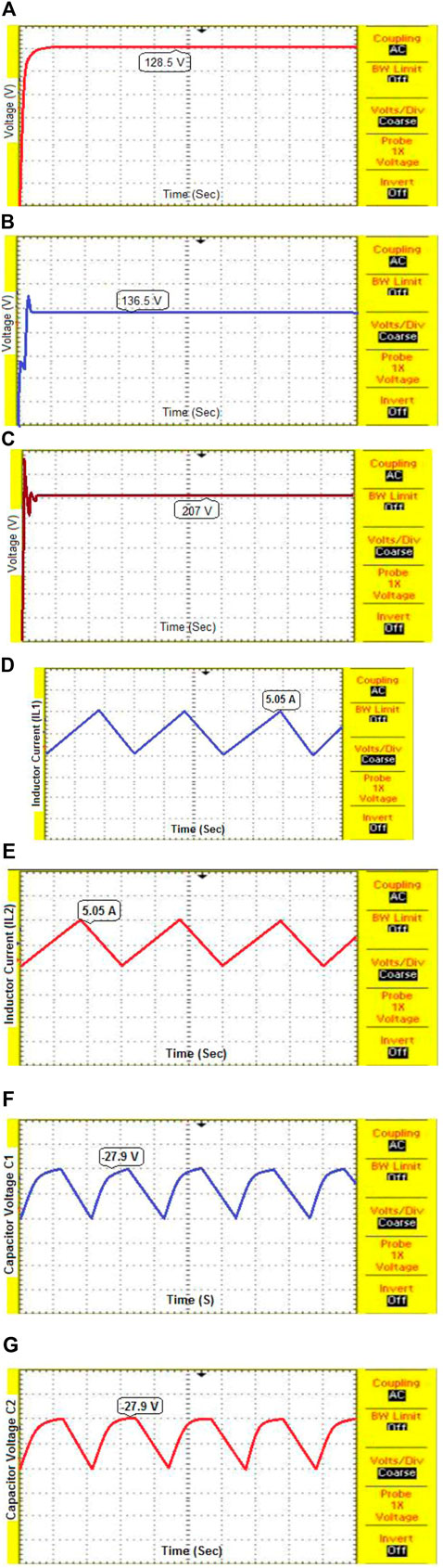
FIGURE 13
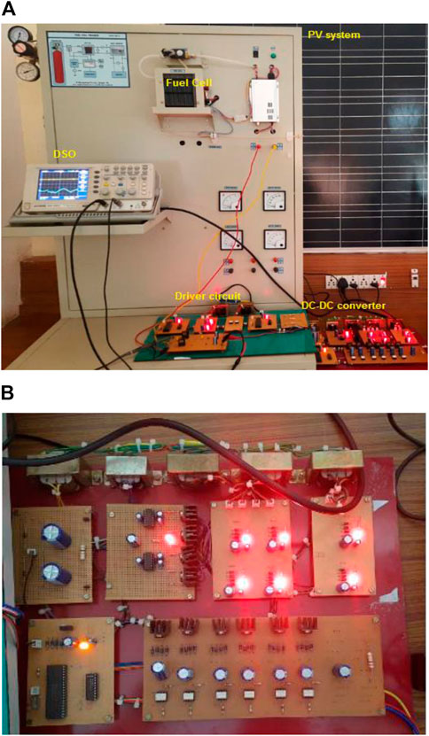
FIGURE 14. (A) Experimental setup (B) non-isolated DC-DC converter.
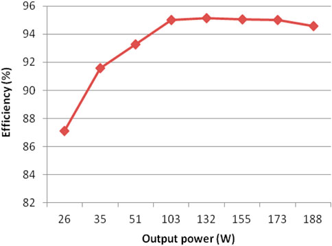
FIGURE 15. The power conversion efficiency under steady state conditions.
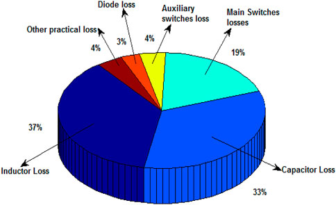
FIGURE 16. The losses contributed by different components of the proposed converter.
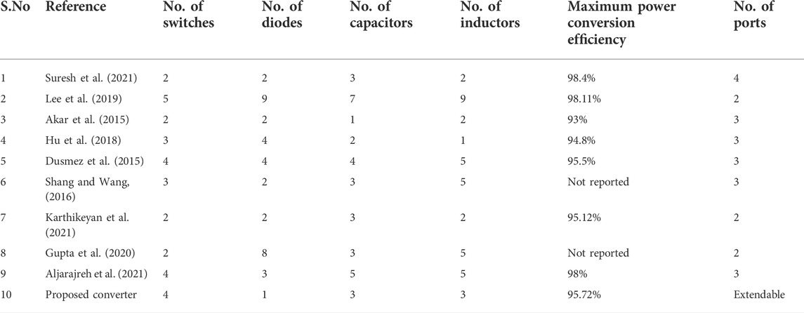
TABLE 2. Performance comparison of various Cuk-derived converters.
The number of main switches used in the proposed converter is two which are considerable less compared to all other converters used in the state of art. The auxiliary switches facilitate the integration of renewable energy sources depending upon the output voltage of source which is inevitable. Taking into account, the total switches considered to be four. Only one diode is used in the proposed converter, which is significantly fewer compared to the number of diodes used in all other converters reported in the literature. Three inductors and capacitors are used in the converter, which is compared against other converters as shown in Table 2. The maximum conversion efficiency achieved by the proposed converter was 95.72%, which is significantly higher than some reported converters (Mamouri et al., 2020; Akar et al., 2015; Hu et al., 2018; Shang and Wang, 2016), but slightly lower than some other converters (Suresh et al., 2021; Lee et al., 2019; Ahmad et al., 2018). The converters used by Suresh et al. (2021) and Aljarajreh et al. (2021) achieved a maximum efficiency of 98.4 and 98%, respectively, which operate in bidirectional mode. The converters used by Suresh et al. (2021) and Aljarajreh et al. (2021) achieved a maximum efficiency of 98.4 and 98%, respectively, which operate in bidirectional mode. The converter used by Lee et al. (2019) achieved a maximum efficiency of 98.11% which operate in unidirectional mode. It is evident that the maximum efficiency of the proposed converter is optimum when operating in a unidirectional mode with the use of a non-isolated converter topology.
8 Conclusion
A dual input single output non-isolated DC-DC converter capable of handling multiple renewable sources of energy for electric vehicle applications was designed. The proposed converter was able to handle two renewable energy sources, such as a solar PV and a PEM fuel cell, that had different electrical characteristics. This converter was analyzed along with various operating control strategies, using MATLAB/R2021a Simulink environment under steady state and with two sources. The results showed that the performance of the proposed converter was superior to other state of the art converters. The hardware results were validated by constructing a 200-W experimental setup in the laboratory. The experimental results closely matched the simulation results, and showed that this converter is suitable for hybrid electric vehicle applications.
The highlights of this paper are listed below:
✓ The proposed converter was able to simultaneously handle two different renewable energy resources that had different electrical characteristics.
✓ The proposed converter made use of one common inductor between two input ports, which reduced the circuit volume and complexity.
✓ The proposed converter achieved a maximum power conversion efficiency of 95.31% under steady state conditions.
Data availability statement
The original contributions presented in the study are included in the article/supplementary material; further inquiries can be directed to the corresponding author.
Author contributions
All authors listed have made substantial, direct, and intellectual contributions to the work and approved it for publication.
Conflict of interest
The authors declare that the research was conducted in the absence of any commercial or financial relationships that could be construed as a potential conflict of interest.
Publisher’s note
All claims expressed in this article are solely those of the authors and do not necessarily represent those of their affiliated organizations, or those of the publisher, the editors and the reviewers. Any product that may be evaluated in this article, or claim that may be made by its manufacturer, is not guaranteed or endorsed by the publisher.
References
Ahmad, F., Haider, A. A., Naveed, H., Mustafa, A., and Ahmad, I. (2018). “Multiple input multiple output DC to DC converter,” in 2018 5th International Multi-Topic ICT Conference (IMTIC) (Jamshoro, Pakistan: IEEE), 1–6.
Akar, F., Tavlasoglu, Y., Ugur, E., Vural, B., and Aksoy, I. (2015). A bidirectional nonisolated multi-input DC–DC converter for hybrid energy storage systems in electric vehicles. IEEE Trans. Veh. Technol. 65 (10), 7944–7955. doi:10.1109/tvt.2015.2500683
Akhil Raj, P., and Arya, S. R. (2021). Solar supplied two-output DC–DC converters in the application of low power. Automatika 62 (2), 172–186. doi:10.1080/00051144.2020.1805859
Aljarajreh, H., Lu, D. D. C., Siwakoti, Y. P., Tse, C. K., and See, K. W. (2021). Synthesis and analysis of three-port DC/DC converters with two bidirectional ports based on power flow graph Technique. Energies 14 (18), 5751. doi:10.3390/en14185751
Dhananjaya, M., and Pattnaik, S. (2021). Review on multi-port DC–DC converters. New Delhi, India: IETE Technical Review, 1–14.
Dusmez, S., Khaligh, A., and Hasanzadeh, A. (2015). A zero-voltage-transition bidirectional DC/DC converter. IEEE Trans. Ind. Electron. 62 (5), 3152–3162. doi:10.1109/tie.2015.2404825
Gupta, N., Almakhles, D., Bhaskar, M. S., Sanjeevikumar, P., Holm-Nielsen, J. B., and Mitolo, M. (2020). “Novel hybrid high gain converter: Combination of cuk and buck-boost structures with switched inductor for DC microgrid,” in 2020 2nd Global Power, Energy and Communication Conference (GPECOM) (Izmir, Turkey: IEEE), 47–52.
Hu, R., Zeng, J., Liu, J., and Yang, J. (2018). Double-input DC-DC converter for applications with wide-input-voltage-ranges. J. Power Electron. 18 (6), 1619–1626.
Iqbal, M. T., and Maswood, A. I. (2020). “A frequency domain based large and small signal modeling of three phase dual active bridge,” in IECON 2020 The 46th Annual Conference of the IEEE Industrial Electronics Society, 3421–3426. doi:10.1109/IECON43393.2020.9254773
Iqbal, M. T., and Maswood, A. I. (2021). An explicit discrete-time large- and small-signal modeling of the dual active bridge DC–DC converter based on the time scale methodology. IEEE J. Emerg. Sel. Top. Ind. Electron. 2 (4), 545–555. doi:10.1109/JESTIE.2021.3087942
Karthikeyan, B., Sundararaju, K., and Palanisamy, R. (2021). A variable step size fuzzy logic controller based maximum power point tracking controller for proton exchange membrane fuel cell powered resonant pulse width modulation high step up converter with multicarrier sinusoidal pulse width modulation inverter fed induction motor. Int. Trans. Electr. Energy Syst. 31 (11). doi:10.1002/2050-7038.13093
Khoramikia, H., Heydari, M., and Dehghan, S. M. (2018). “A new three-port non-isolated DC-DC converter for renewable energy sources application,” in Electrical Engineering (ICEE), Iranian Conference on (Mashhad, Iran: IEEE), 1101–1106.
Lee, W. S., Kim, J. H., Lee, J. Y., and Lee, I. O. (2019). Design of an isolated DC/DC topology with high efficiency of over 97% for EV fast chargers. IEEE Trans. Veh. Technol. 68 (12), 11725–11737. doi:10.1109/tvt.2019.2949080
Mamouri, L., Mesbahi, T., Bartholomeus, P., and Théophile, P. A. U. L. (2020). “Design of a DC/DC power converter for Li-ion battery/supercapacitor hybrid energy storage system in electric vehicles,” in 2020 IEEE Vehicle Power and Propulsion Conference (VPPC) (Gijon, Spain: IEEE), 1–5.
Shang, M., and Wang, H. (2016). “A ZVS integrated single-input-dual-output DC/DC converter for high step-up applications,” in 2016 IEEE Energy Conversion Congress and Exposition (ECCE) (Milwaukee, WI, USA: IEEE), 1–6.
Suresh, K., Bharatiraja, C., Chellammal, N., Tariq, M., Chakrabortty, R. K., Ryan, M. J., et al. (2021). A multifunctional non-isolated dual input-dual output converter for electric vehicle applications. IEEE Access 9, 64445–64460. doi:10.1109/access.2021.3074581
Keywords: non-isolated, dual input single output, high step up, multisource, electric vehicle
Citation: Karthikeyan B, Sundararaju K, Palanisamy R, Manivasagam R, Hossain I, Bajaj M, Shouran M, Abdul samad B and Kamel S (2022) A dual input single output non-isolated DC-DC converter for multiple sources electric vehicle applications. Front. Energy Res. 10:979539. doi: 10.3389/fenrg.2022.979539
Received: 27 June 2022; Accepted: 09 August 2022;
Published: 15 September 2022.
Edited by:
Fernando Martinez-Rodrigo, University of Valladolid, SpainReviewed by:
Mohamed Salem, Universiti Sains Malaysia (USM), MalaysiaMohammad Tauquir Iqbal, Nanyang Technological University, Singapore
Copyright © 2022 Karthikeyan, Sundararaju, Palanisamy, Manivasagam, Hossain, Bajaj, Shouran, Abdul samad and Kamel. This is an open-access article distributed under the terms of the Creative Commons Attribution License (CC BY). The use, distribution or reproduction in other forums is permitted, provided the original author(s) and the copyright owner(s) are credited and that the original publication in this journal is cited, in accordance with accepted academic practice. No use, distribution or reproduction is permitted which does not comply with these terms.
*Correspondence: Bdereddin Abdul samad, YWJkdWxzYW1hZGJmQGNhcmRpZmYuYWMudWs=