 Shu Xiong
 Yucui Yang1,2
95% of researchers rate our articles as excellent or good
Learn more about the work of our research integrity team to safeguard the quality of each article we publish.
Find out more
ORIGINAL RESEARCH article
Front. Energy Res. , 22 July 2022
Sec. Smart Grids
Volume 10 - 2022 | https://doi.org/10.3389/fenrg.2022.977077
This article is part of the Research Topic Increasing Penetration of Renewable Sources in Power Systems: Opportunities and Challenges View all 18 articles
Reluctance machines with DC field coil in stator are a competitive candidate for starter generation application, due to the elimination of rare-earth permanent magnet (PM), robust structures, and controllable excitation. However, due to the poor excitation ability of DC field coils, the torque density is disadvantageous. Moreover, with the increase in the DC field current, it is exposed to the risk of extra DC saturation in stator teeth. As a consequence, the torque density and efficiency are both constrained. To solve the aforementioned problems, based on the comprehensive consideration of production cost and torque performance, this study proposed a novel type of hybrid reluctance machine with dual-ferrite–assisted in stator slots. The inner-layer ferrite PM is magnetized tangentially, which can effectively achieve the DC-saturation–relieving effect, while the outer-layer ferrite PM is magnetized radially to increase the machine torque density through the flux modulation effect. Based on finite element analysis, the machine torque density and efficiency can be improved by 20 and 5%, respectively. Furthermore, to simplify the excitation system of the DC terminal, a two-stage excitation method is proposed by splitting some turns of armature winding to feed DC field winding with passive rectifier. No power switching devices are needed for the excitation system in this way, making the system highly robust. The effectiveness of the proposed design is verified by time-stepping finite element analysis.
Due to high torque density and high efficiency, the rare-earth permanent magnet (PM) machines have been widely used in electrical vehicles and wind power generation systems (Zhu and Howe, 2007; Chau et al., 2008; Pellegrino et al., 2012; Sarlioglu and Morris, 2015; Zhao et al., 2018; Gong et al., 2019; Zhao et al., 2020a; Zhao et al., 2021; Zhao et al., 2022a), which enables the increasing penetration of renewable energy into traditional power systems, driving to a carbon-free future. However, the rare-earth PM is a non-renewable resource and its supply status is unstable with a relatively high price, which is desired to be reduced in electrical machine systems (Polinder et al., 2006; Fasolo et al., 2014; Niu et al., 2019). The switched reluctance motor (SRM) is a potential non-PM solution (Polinder et al., 2006; Niu et al., 2019), but the core of SRM can only operate in the first quadrant of the BH curve, thus torque density is poorer than that of the PM machine. In addition, the torque ripple is serious due to its half-cycle conducting principle.
A doubly-fed doubly salient machine (DF-DSM) has a similar stator and rotor structure with SRM. The difference is that the space of the stator slot is shared by DC coils and AC coils. This allows DF-DSM to operate in a whole electric period and be driven by a universal inverter (Fasolo et al., 2014; Zhao et al., 2020b; Zhao et al., 2022b). Nevertheless, its torque ripple is severe due to rich even-order flux harmonics and asymmetric magnetic circuits between phases. To address this issue, another structure named as variable flux reluctance machine (VFRM) is proposed, which can be designed with more flexible slot pole combinations (Xue et al., 2010). In particular, with the design of odd rotor pole pair, the even-order harmonics in flux linkage can be canceled, and symmetrical magnetic circuits between phases are obtained. Therefore, lower cogging torque and small torque ripple can be acquired (Takeno et al., 2012; Hu et al., 2020). Unfortunately, the torque density of VFRM is still lower than that of SRM and quite lower than that of PM machines. Two reasons behind this are, on one hand, the excitation ability of DC field coils is much poor compared to rare-earth PMs. On the other hand, DC field windings produce a DC flux bias in the stator core, making it prone to magnetic saturation. This problem is severe under heavy load conditions, which degrades torque performance and increases core loss. To solve this issue, tangential PMs can be embedded in slots to create an opposite magnetic bias against that of DC field winding (Liu and Zhu, 2013; Lee et al., 2014; Liu and Zhu, 2014; Wang et al., 2016; Zhu et al., 2016; Ullah et al., 2019; Zhao et al., 2019; Zhao et al., 2020c), hence weakening the magnetic saturation in the stator core.
This study proposed a new hybrid reluctance machine (HRM) using dual-ferrite magnets in stator slots. The inner-layer ferrite PMs are used to release the saturation of the magnetic circuit due to extra DC bias generated by DC field winding. The outer-layer ferrite PMs contribute to the effective flux linkage and torque boost effect through the flux modulation effect. In this way, the proposed HRM can achieve improved torque density and efficiency at the same time compared to the traditional non-PM design. The cost increase due to ferrite magnets is acceptable as well. Moreover, to simplify the excitation system of the DC current terminal, a two-stage excitation method is proposed by splitting some turns of armature winding to feed DC field winding with passive rectifier. No power switching devices are needed for the excitation system in this way, making the system highly robust. The rest of the study is arranged as follows. In Section 2, the configuration and principle of the proposed HRM are introduced. In Section 3, different pole pair combinations are compared through finite element analysis, including magnetic field distribution, cogging torque, and back electromotive force. In Section 4, the electromagnetic performance of the optimal design is analyzed, with emphasis on the effect of dual-layer ferrite PMs on the magnetic saturation and torque generation. In Section 5, the feasibility of a power device free two-stage excitation system is verified by field-circuit co-simulation, proving its potential for stater generator applications. Some conclusions are drawn in Section 6.
The structure of the proposed dual-ferrite–assisted HRM is shown in Figure 1. It uses a doubly salient structure. There are two sets of windings in the stator, namely, DC field winding and AC armature winding. The AC armature winding uses a single-layer concentrated connection, thus the winding ends are short and good isolation can be achieved. The rotor consists of an iron core only, providing good mechanical robustness. Dual-ferrite PMs are introduced in stator slots and play different roles in the electromagnetic characteristics of the proposed HRM. Extra pole shoes can be designed to enable the placement of slot PMs and make sure the mechanical strength requirement. Considering the winding ends are usually the hotpots in an electrical machine system. The ferrite magnets are likely to be exposed to the demagnetization risk. Some advanced natural/water/oil cooling methods can be used to bring down the temperature rise and thus ensure the working environment of magnets. As shown in Figure 2A, the inner ferrite PMs are tangentially magnetized to generate a magnetic bias opposite to that of DC field windings, and in this way, the saturation of the magnetic circuit can be reduced, namely, DC-saturation–relieving (DCSR) effect in this study. It is worth noting that the inner-layer ferrite PMs only adjust the offset of the flux linkage and have little influence on the phase angle. The outer-layer radially magnetized ferrite PMs will create extra flux that overlaps with that of DC field winding, as shown in Figure 2B, and thus boost torque density. The working principle of dual-layer ferrites is expanded as follows:
where
where
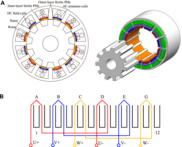
FIGURE 1. (A) Structure of the proposed HRM. (B) Armature winding connection.
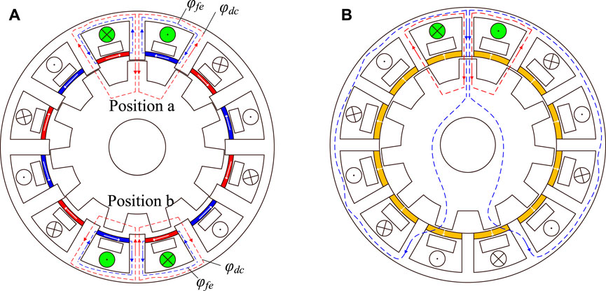
FIGURE 2. Flux linkage distribution. (A) Inner-layer ferrite PMs and DC field coils. (B) Outer-layer ferrite PMs and DC field coils. The flux linkage excited by DC field winding can be expanded by Fourier series.
As shown, the DC flux bias in the stator core is determined by the magnetomotive force of DC field winding and average rotor permeance. To avoid the flux saturation in the stator teeth, inner-layer ferrite PMs are introduced to achieve the DCSR effect. As shown in Figure 3, without DCSR, the phase flux linkage has a bias with
where
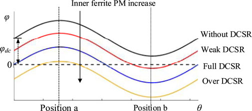
FIGURE 3. Schematic coil flux with the increase in inner-layer ferrite PMs.
The outer-layer ferrite PMs and the adjacent stator tooth form the magnetic poles, and the ferrite PM field is modulated by rotor salient poles. At the same time, the redundant air-gap harmonics are excited to boost the torque generation. The rotational speed
where
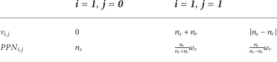
TABLE 1. Dominant harmonics excited by outer-layer ferrite PMs.
When
The electromagnetic torque produced by outer-layer ferrite PMs can be defined as:
where
In the proposed HRM, the magnetic circuits between phases are entirely symmetrical. Four slot pole combinations of 12/10, 12/11, 12/13, and 12/14 are selected to be analyzed in this study. Since the proposed HRM should use a single-layer concentrated connection, the vector diagram of winding connection for each design is presented in Figure 4. In 12/10 and 12/14 cases, the armature coils in opposite positions are positively cascaded as they have the same phase of flux linkage, while the phase flux of 12/11 and 12/13 cases in opposite positions is delayed by the half electrical period, and hence they are negatively cascaded. The detailed design parameters and the specifications of major machine materials are presented in Tables 2, 3,.
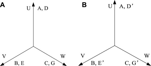
FIGURE 4. Winding configuration. (A) 12/10 and 12/14. (B) 12/11 and 12/13.
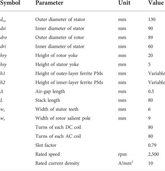
TABLE 2. Design parameters for the proposed machine.
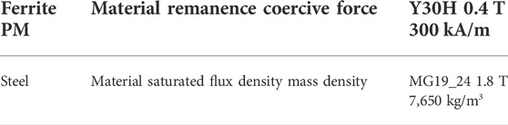
TABLE 3. Major parameters and specifications.
The flux distributions of the proposed HRM with four pole pair combinations are illustrated in Figure 5, with a DC field current of 5A. It is clear to see that the flux linkage circulates into a loop according to the wounded stator tooth, aligned rotor tooth, and the adjacent stator teeth. As shown in Figure 5, the phase U is composed of coil A and coil D, the flux of phase U of 12/10 and 12/14 can be derived by using Fourier series as:
For 12/11 and 12/13, the coil A and coil D are negatively connected, and then the flux of phase U can be rewritten as:
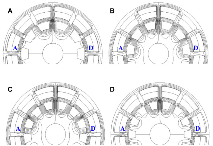
FIGURE 5. Flux distribution generated by DC field coils and dual-layer ferrite PMs (A) 12/10. (B) 12/11. (C) 12/13. (D) 12/14.
As demonstrated by equation (10), in 12/11 and 12/13 cases, the DC flux bias and all even-order harmonics are canceled in the combined phase. As the flux linkage and its harmonic orders are compared in Figure 6, the 12/11 and 12/13 cases can acquire more symmetrical flux linkage without any even-order harmonics. In addition, the fundamental components of flux linkage of 12/10 and 12/11 cases are larger than the others. As shown in Figure 7, the cogging torques of 12/11 and 12/13 are quite smaller than those of 12/10 and 12/14. This is because a smaller or least common multiple of the stator teeth number and rotor pole pair may cause bigger cogging torque. Based on the aforementioned analysis, the 12/11 case is a suitable pole pair combination for the proposed dual-ferrite HRM.
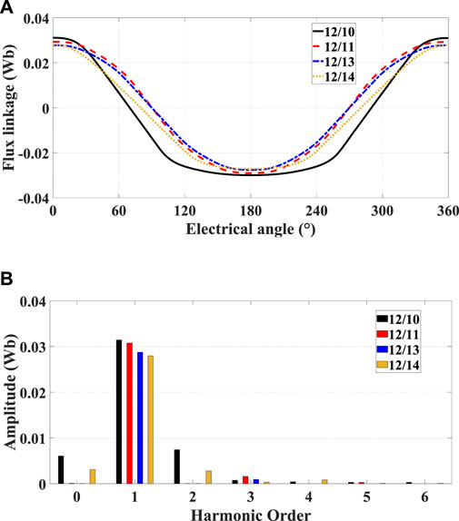
FIGURE 6. (A) Phase flux linkage waveforms. (B) Harmonic distribution.
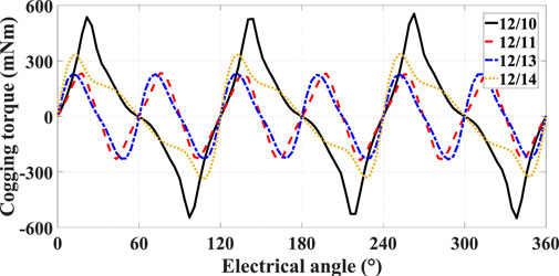
FIGURE 7. Cogging torque waveforms.
The usage of dual-layer ferrite PMs is a key parameter for the proposed HRM. On one side, the over usage of ferrite PMs may occupy the space of DC coils and AC coils, which leads to a decrease in the torque density. On the other side, insufficient ferrite PMs cannot produce enough flux modulation and DCSR effect. Under different current densities, the suitable usage of dual-layer ferrite magnets is analyzed and the results are given in Figure 8. Under low current densities, the outer-layer ferrite PM plays a significant role, as shown in Figure 8A. With the increase in outer-layer ferrite PMs, the average torque increases distinctly. By contrast, the inner-layer ferrite magnets are less important since flux saturation is not serious under low current density. As shown in Figure 8C, the inner-layer ferrite PMs start to show their effect. With the increase in the usage, the average torque increases significantly. Figure 8B describes the combined effect of dual-layer ferrite PMs. With the increase in dual-layer ferrite PMs, the average torque increases first and then shows a downward trend, proving that the overuse of ferrite PMs may cause a negative effect on torque generation. Consequently, the usage of ferrite magnets is designed as 4 mm for inner-layer ferrite and 1 mm for outer-layer ferrite to achieve the maximum average torque at a rated current density of 15 A/mm2.

FIGURE 8. Average torque with variable usage of dual-ferrite PMs under different current densities (A) 5 A/mm2. (B) 10 A/mm2. (C) 15 A/mm2.
Figure 9 presents the harmonics excited by the DC field coils, outer-layer ferrite PMs, and AC armature coils, respectively. According to the flux modulation effect, if the harmonics excited by DC coils and outer-layer ferrite PMs have the same rotational speed and the same pole pair number as AC harmonics, the torque density can be improved. Figure 9A shows the air-gap flux density with only DC field excitation, and its harmonics distribution obtained by the fast Fourier transform (FFT). Figure 9B shows the flux density of outer-layer ferrite PMs and its FFT of the main harmonic components. The orders of dominant harmonic components of two excitation sources are quite different. When compared the redundant harmonics excited by armature excitation using a single-layer concentrated winding connection as shown in Figure 9C, it can be concluded that both DC excitation and outer-layer ferrite excitation contribute to torque density improvement effectively.
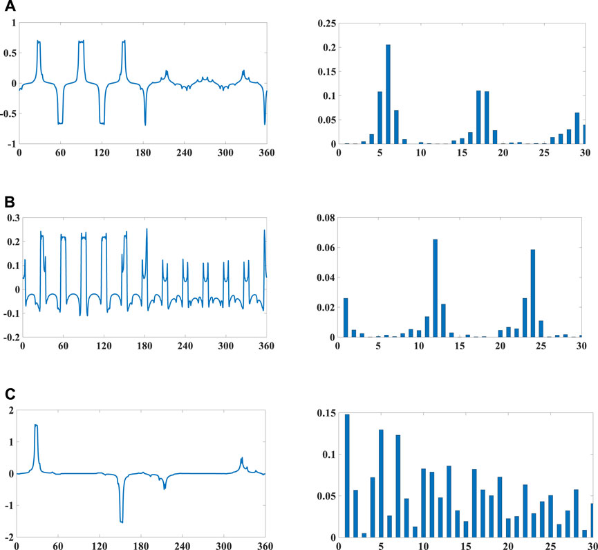
FIGURE 9. Flux density in the air gap and its harmonic distribution. (A) Only DC 5A. (B) Only outer-layer ferrite PMs. (C) Only AC armature current 5A.
When the proposed HRM is excited by DC coils only, the magnetic circuit distribution under the no-load condition is shown in Figure 10A. The magnetic circuit in the stator teeth is severely saturated, which will seriously affect the torque performance and efficiency. With the help of inner-layer ferrite PMs, the magnetic circuit saturation in the stator slots and teeth is effectively released by the DCSR effect, which is shown in Figure 10B. Meanwhile, as shown in Figure 11, compared with the torque performance excited by the DC field current only, the torque density of the proposed dual-ferrite–assisted HRM has been improved by more than 20%. Also, the efficiency can be increased by 5% due to core loss mitigation, as indicated in the simulation data in Table 4.
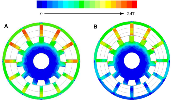
FIGURE 10. Magnetic field distribution at different excitation statuses. (A) DC field current only. (B) DC field current and dual-ferrite PMs.
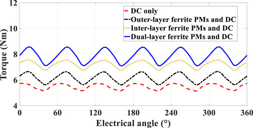
FIGURE 11. Steady torque curves at different excitation statuses.
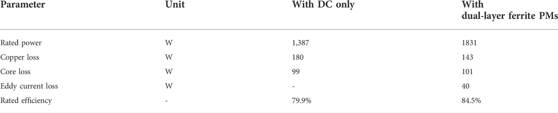
TABLE 4. Power, loss, and efficiency.
Figure 12 presents the two-stage excitation system for the proposed HRM, based on the field-circuit co-simulation (combined with the finite element electromagnetic field analysis and circuit transition analysis). The key is to split a few turns of the AC armature winding to function as an AC supply winding to feed the DC field winding through the passive diode rectifier. In this way, the extra exaction circuit for the DC field terminal can be eliminated, including the switching devices and related control systems, thereby making the system highly robust. This two-stage excitation system is an ideal solution for stable generation mode as a stater generator candidate. Figure 13 shows the simulation results of the rectified current and voltage excitation in the DC field terminal through the AC supply winding and diode rectifier. It is observed that the DC field voltage and current excitation can naturally achieve a stable value after a certain time, which verifies the system effectiveness.
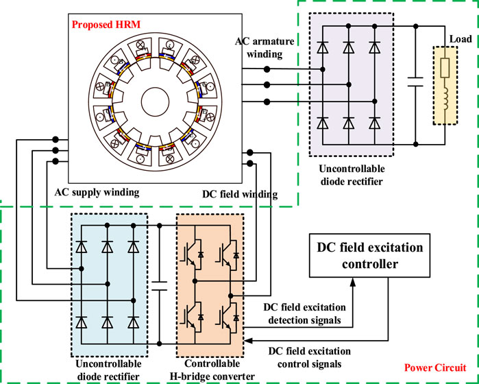
FIGURE 12. Two-stage excitation system for the proposed HRM.
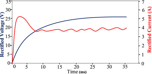
FIGURE 13. Rectified voltage and current in the DC field terminal.
A novel dual-ferrite–assisted HRM is proposed in this study. The key is to apply the inner-layer ferrite PM to achieve the DCSR effect and the outer-layer ferrite PM to help modulate the air-gap flux and thus increase the torque density. Four pole pair combinations of the proposed machine are compared in terms of flux harmonics and cogging torque, and the optimal case is selected for further analysis. The effect of ferrite PM usage on torque generation is evaluated. The combined effects of dual-layer ferrite PMs are verified by FEA, which reveals that, with the flux modulation effect and DCSR effect, the torque density and efficiency can be increased by 20 and 5%, respectively. Furthermore, the two-stage excitation system is verified by field-circuit co-simulation, which verifies that the proposed solution is very suitable for a stater generator application with enhanced electromagnetics performance at the starting mode and simplified power circuit at the generation mode.
The original contributions presented in the study are included in the article/Supplementary Materials; further inquiries can be directed to the corresponding author.
Writing—original draft preparation and supervision: SX. Writing—review and editing: YY. Writing—review and editing: JP.
The authors declare that the research was conducted in the absence of any commercial or financial relationships that could be construed as a potential conflict of interest.
All claims expressed in this article are solely those of the authors and do not necessarily represent those of their affiliated organizations, or those of the publisher, the editors, and the reviewers. Any product that may be evaluated in this article, or claim that may be made by its manufacturer, is not guaranteed or endorsed by the publisher.
Chau, K. T., Chan, C. C., and Liu, C. (2008). Overview of permanent-magnet brushless drives for electric and hybrid electric vehicles. IEEE Trans. Ind. Electron. 55 (6), 2246–2257. doi:10.1109/tie.2008.918403
Fasolo, A., Alberti, L., and Bianchi, N. (2014). Performance comparison between switching-flux and IPM machines with rare-earth and ferrite PMs. IEEE Trans. Ind. Appl. 50 (6), 3708–3716. doi:10.1109/tia.2014.2319592
Gong, C., Hu, Y., Gao, J., Wang, Y., and Yan, L. (2019). An improved delay-suppressed sliding-mode observer for sensorless vector-controlled PMSM. IEEE Trans. Ind. Electron. 67 (7), 5913–5923. doi:10.1109/tie.2019.2952824
Hu, Y., Xiao, L., Pan, C., Li, J., and Wang, C. (2020). Multidomain analysis and nth-order synchronous reference vector adaptive control of the doubly salient motor. IEEE Trans. Power Electron. 35 (9), 9563–9573. doi:10.1109/tpel.2020.2970459
Lee, C. H. T., Chau, K. T., Liu, C., Ching, T. W., and Li, F. (2014). Mechanical offset for torque ripple reduction for magnetless double-stator doubly salient machine. IEEE Trans. Magn. 50 (11), 1–4. doi:10.1109/tmag.2014.2320964
Liu, X., and Zhu, Z. Q. (2013). Comparative study of novel variable flux reluctance machines with doubly fed doubly salient machines. IEEE Trans. Magn. 49 (7), 3838–3841. doi:10.1109/tmag.2013.2242047
Liu, X., and Zhu, Z. Q. (2014). Stator/rotor Pole combinations and winding configurations of variable flux reluctance machines. IEEE Trans. Ind. Appl. 50 (6), 3675–3684. doi:10.1109/tia.2014.2315505
Niu, S., Sheng, T., Zhao, X., and Zhang, X. (2019). Operation principle and torque component quantification of short-pitched flux-bidirectional-modulation machine. IEEE Access 7, 136676–136685. doi:10.1109/access.2019.2942482
Pellegrino, G., Vagati, A., Guglielmi, P., and Boazzo, B. (2012). Performance comparison between surface-mounted and interior PM motor drives for electric vehicle application. IEEE Trans. Ind. Electron. 59 (2), 803–811. doi:10.1109/tie.2011.2151825
Polinder, H., van der Pijl, F. F. A., de Vilder, G. J., and Tavner, P. J. (2006). Comparison of direct drive and geared generator concepts for wind turbines. IEEE Trans. Energy Convers. 21 (3), 725–733. doi:10.1109/tec.2006.875476
Sarlioglu, B., and Morris, C. T. (2015). More electric aircraft: Review, challenges, and opportunities for commercial transport aircraft. IEEE Trans. Transp. Electrific. 1 (1), 54–64. doi:10.1109/tte.2015.2426499
Takeno, M., Chiba, A., Hoshi, N., Ogasawara, S., Takemoto, M., Rahman, M. A., et al. (2012). Test results and torque improvement of the 50-kW switched reluctance motor designed for hybrid electric vehicles. IEEE Trans. Ind. Appl. 48 (4), 1327–1334. doi:10.1109/tia.2012.2199952
Ullah, S., McDonald, S. P., Martin, R., Benarous, M., and Atkinson, G. J. (2019). A permanent magnet assist, segmented rotor, switched reluctance drive for fault tolerant aerospace applications. IEEE Trans. Ind. Appl. 55 (1), 298–305. Jan.-Feb. 2019. doi:10.1109/tia.2018.2864718
Wang, Y., Zhang, Z., Liang, R., Yuan, W., and Yan, Y. (2016). Torque density improvement of doubly salient electromagnetic machine with asymmetric current control. IEEE Trans. Ind. Electron. 63 (12), 7434–7443. doi:10.1109/tie.2016.2594761
Xue, X. D., Cheng, K. W. E., Ng, T. W., and Cheung, N. C. (2010). Multi-objective optimization design of in-wheel switched reluctance motors in electric vehicles. IEEE Trans. Ind. Electron. 57 (9), 2980–2987. doi:10.1109/tie.2010.2051390
Zhao, X., Jiang, J., Niu, S., and Wang, Q. (2022). Slot-PM-assisted hybrid reluctance generator with self-excited DC source for stand-alone wind power generation. IEEE Trans. Magn. 58 (2), 1–6. doi:10.1109/tmag.2021.3081585
Zhao, X., Niu, S., and Fu, W. (2019). A new modular relieving-DC-saturation vernier reluctance machine excited by zero-sequence current for electric vehicle. IEEE Trans. Magn. 55 (7), 1–5. doi:10.1109/tmag.2018.2887271
Zhao, X., Niu, S., and Fu, W. (2018). Design of a novel parallel-hybrid-excited dual-PM machine based on armature harmonics diversity for electric vehicle propulsion. IEEE Trans. Ind. Electron. 66 (6), 4209–4219. doi:10.1109/tie.2018.2863211
Zhao, X., Niu, S., and Fu, W. (2020). Sensitivity analysis and design optimization of a new hybrid-excited dual-PM generator with relieving-DC-saturation structure for stand-alone wind power generation. IEEE Trans. Magn. 56 (1), 1–5. doi:10.1109/tmag.2019.2951078
Zhao, X., Niu, S., Zhang, X., and Fu, W. (2020). A new relieving-DC-saturation hybrid excitation vernier machine for HEV starter generator application. IEEE Trans. Ind. Electron. 67 (8), 6342–6353. doi:10.1109/tie.2019.2939966
Zhao, X., Niu, S., Zhang, X., and Fu, W. (2020). Design of a new relieving-DC-saturation hybrid reluctance machine for fault-tolerant in-wheel direct drive. IEEE Trans. Ind. Electron. 67 (11), 9571–9581. doi:10.1109/tie.2019.2955418
Zhao, X., Niu, S., Zhang, X., and Fu, W. (2021). Flux-modulated relieving-DC-saturation hybrid reluctance machine with synthetic slot-PM excitation for electric vehicle in-wheel propulsion. IEEE Trans. Ind. Electron. 68 (7), 6075–6086. doi:10.1109/tie.2020.2996140
Zhao, X., Wang, S., Niu, S., Fu, W., and Zhang, X. (2022). A novel high-order-harmonic winding design method for vernier reluctance machine with DC coils across two stator teeth. IEEE Trans. Ind. Electron. 69 (8), 7696–7707. doi:10.1109/tie.2021.3104589
Zhu, Z. Q., and Howe, D. (2007). Electrical machines and drives for electric, hybrid, and fuel cell vehicles. Proc. IEEE 95 (4), 746–765. doi:10.1109/jproc.2006.892482
Keywords: dual-ferrite magnets, DC-saturation-relieving, hybrid reluctance machine, starter generator application, two-stage excitation
Citation: Xiong S, Yang Y and Pan J (2022) A new dual-ferrite–assisted hybrid reluctance machine with two-stage excitation for starter generator application. Front. Energy Res. 10:977077. doi: 10.3389/fenrg.2022.977077
Received: 24 June 2022; Accepted: 04 July 2022;
Published: 22 July 2022.
Edited by:
Minghao Wang, Hong Kong Polytechnic University, Hong Kong SAR, ChinaCopyright © 2022 Xiong, Yang and Pan. This is an open-access article distributed under the terms of the Creative Commons Attribution License (CC BY). The use, distribution or reproduction in other forums is permitted, provided the original author(s) and the copyright owner(s) are credited and that the original publication in this journal is cited, in accordance with accepted academic practice. No use, distribution or reproduction is permitted which does not comply with these terms.
*Correspondence: Shu Xiong, eGlvbmdzaHVva0AxNjMuY29t
Disclaimer: All claims expressed in this article are solely those of the authors and do not necessarily represent those of their affiliated organizations, or those of the publisher, the editors and the reviewers. Any product that may be evaluated in this article or claim that may be made by its manufacturer is not guaranteed or endorsed by the publisher.
Research integrity at Frontiers
Learn more about the work of our research integrity team to safeguard the quality of each article we publish.