 Chaoli Gao1,2
 Song Li
- 1State Key Laboratory of Petroleum Resources and Prospecting, China University of Petroleum, Beijing, China
- 2Exploration and Development Technology Research Institute, Yanchang Oil Field Co., LTD., Yanan, China
- 3School of Oil and Natural Gas Engineering, Southwest Petroleum University, Chengdu, China
- 4Southwest Oil and Gas Field Company of CNPC Chengdu, Chengdu, China
- 5Technology and Information Management Department of Yanchang Oilfield Co., Ltd., Yanan, China
- 6Engineering Research Institute of PetroChina Southwest Oil and Gasfield Company, Chengdu, China
The physical property of Chang 6 reservoir in Yanchang oilfield is poor, and the heterogeneity is strong. Multistage fracturing of horizontal wells is easy to form only one large horizontal fracture, but it is difficult to control the fracture height and length. The new mining method of “bow horizontal well + multistage horizontal joint” can effectively increase the multistage horizontal joint’s spatial position, which improves the drainage area and stimulation efficiency of oil wells. Due to the reservoir’s low permeability and strong heterogeneity, the single well mode of “bow horizontal well + multistage horizontal fracture” cannot effectively produce Chang 6 reservoir. To improve the production degree of the g 6 reservoir, the fracture model is established using equivalent conductivity and the multigrid method. The pressure response functions of horizontal wells and volume fracturing horizontal wells are established by using the source function, and the relationship between reservoir permeability and starting pressure gradient in the block is calculated. On this basis, the reservoir productivity equation of the block is established, which provides a basis for optimizing the fracturing design parameters of horizontal wells. It is proposed that the flow unit should be considered in the design of fracturing parameters of horizontal fractures, the number of fractures should comprehensively consider whether the fractures can make each flow unit be used, and have large controlled reserves, and the scale of fracturing should comprehensively consider the output and cost. The fracture network model is established by using equivalent conductivity and multi-gridthod, and the volume fracturing design parameters of horizontal wells are optimized, considering the seepage characteristics of the flow unit. The fracturing design parameters of the horizontal section are further defined, which provides a theoretical basis for the efficient development of shallow tight reservoirs.
1 Introduction
With the development of the global economy, the exploration and development process of oil and gas resources continues to expand, and a tight sandstone reservoir has been proven to be a main force in the world energy supply (Li et al., 2018; Xu et al., 2019a). A tight sandstone reservoir is typically classified as a reservoir with permeability less than 0.1 mD, which is not economically producible for a long history (Kazemi, 1982; Li et al., 2019). Qilicun oilfield, which is a typical tight sandstone reservoir, is located in the southeast of the Yishan slope in the Ordos Basin of China. The main oil layer for development is Chang 6 oil layer. The buried depth of this layer is shallow, and the reservoir is thin-layer interactive deposition, but the physical property is poor and the heterogeneity is strong. According to the statistics of existing core analysis reports in the study area, the reservoir porosity distribution is close to the normal distribution, with the main distribution range of 8.1%–10.1% and the average porosity of 9.4%; The permeability gradient is large, ranging from 0.02 to 8.8 mD, and the average permeability is 1.1 mD, tight sandstones exhibit the characteristics of small pore size and low porosity. Especially, for deep tight gas sandstone reservoirs, their pore sizes range from nanometers to micrometers after compaction and solidification for a long time, some scholars have carried out experimental and simulation research on the influence of rock microstructure on gas transmission in tight reservoirs (Meng et al., 2014; Du et al., 2015; Xu et al., 2018; Zhang et al., 2018; Xu et al., 2019b). In recent years, horizontal wells have been widely used in the development of unconventional reservoirs. Horizontal wells combined with multi-stage hydraulic fracturing technology are the main technical means for efficient development of low-permeability and tight reservoirs, which can greatly increase the production of single wells and improve the overall economic benefits of the oilfield (Xiong et al., 2012; Wang et al., 2014; Su et al., 2018a; Su et al., 2018b; Jiang et al., 2018; Su et al., 2020; Zhang et al., 2020). Generally, the direction of the minimum principal stress in the reservoir is horizontal, so the pressure fractures are vertically developed. Multi-stage fracturing in a horizontal well has proven to be effective for the development of unconventional shale resources (Mutalik and Gibson, 2008; King, 2010; Wellhoefer et al., 2014). Long horizontal wells combined with multi-stage fracturing can effectively increase the contact area between the oil well and the reservoir (Zhang et al., 2004; Weng et al., 2011; Chang, 2013; Li et al., 2013; Yang et al., 2014; Westwood et al., 2017; Zhang et al., 2018).
With this technique, large amounts of fracturing fluid are sequentially injected into different stages to simultaneously initiate multiple perforation clusters within one stage, creating dozens of hydraulic fractures (HFs) along the horizontal segment to maximize access to productive zones (Yew and Weng, 2015). However, monitoring during fracturing has found that the actual stimulated volume is much smaller than that interpreted via microseismic mapping (Xu et al., 2016), implying that considerable areas between two fractures may not be effectively stimulated. Xiong et al. (2020) developed the small cluster and stage spacings to further increase the area of fracture surfaces in reservoirs. Dohmen et al. (2014) and Somanchi et al. (2017) believed that strong stress interference among multiple fractures under such a tight spacing can induce nonuniform simultaneous growth (or asymmetrical growth of subsequent fractures, which may considerably undermine the stimulation performance. Zhang et al. (2021) proposed a novel experimental process to model the simultaneous and sequential propagation of multiple closely spaced fractures, and rock splitting and 3D reconstruction technology were used to characterize HF geometries. They investigated the effects of the number of clusters per stage, stage spacing, and net pressure in the previously created fractures on the propagation geometries. Thus, the interference mechanism among multiple closely-spaced fractures in the simultaneous and sequential propagation of multi-stage fracturing should be clarified to improve the effectiveness of fracturing.
HanYi Wang (2016) presented a fully coupled hydraulic fracture propagation model based on the Extended Finite Element Method (XFEM), Cohesive Zone Method (CZM), and Mohr-Coulomb theory of plasticity, which investigated the interference and coalescence of fluid-driven hydraulic fractures that initiated from horizontal wells (Wang, 2016). Hillerborg et al. (1976) introduced the concept of fracture energy into the cohesive crack model and proposed several tractions–displacement relationships. Based on this conception, Mokryakov (2011) proposed an analytical solution for hydraulic fracture with Barenblatt’s cohesive tip zone, the results demonstrate that the derived solutions from the cohesive tip zone model can fit the pressure log much more accurately than LEFM for the case of fracturing soft rock. Wang et al. (2016) developed a cohesive poro-elastoplastic hydraulic fracture model for both brittle and ductile rocks. Their work indicates that plastic damage during fracturing execution can lead to higher propagation pressure and shorter and wider fracture geometry. Lecampion et al. (2015) (Brice and Jean, 2015) developed a numerical model for the initiation and growth of an array of parallel radial hydraulic fractures, and the solution accounts for fracture growth, coupling between elastic deformation and fluid flow in the fractures, elastic stress interactions between fractures and fluid flow in the wellbore.
Bunger et al. (2011) proposed that production forecasting analysis is used by assuming sim straight-linedined fractures to optimize spacing and staging between fractures, but in reality, fractures tend to propagate in a complex manner when they are closely spaced or where preexisting fractures exist. El Rabba (1989) studied that simultaneous fracturing of closely spaced clusters may cause fracture interferences such that some of the fractures stop in between, and some may not even initiate due to the stress shadow effects. Thus, the design of efficient systems can benefit from hydraulic fracture simulations that couple fluid flow to fracture deformation and fracture mechanics principles. The numerical method that can accurately model 2D or 3D fracture propagation can help to understand and improve the fracturing process. The growth of multiple simultaneous fractures assuming no fluid flow inside the fractures has been studied, and simulated the sequential fracturing has been treated with no explicit fluid. Some studies (Rafiee et al., 2012) have utilized stress analysis to suggest a modification to the zipper fracturing to improve the SRV based on heuristic arguments of complexity. However, more rigorous modeling is needed to better understand the problem and to help improve the design. Sesetty and Ahmad (2015) presented a fully coupled DD-based fracturing model, which considered different boundary conditions to simulate the effect of previously created fractures as pressurized (during the flow back is restricted) and propped (proppant filled fracture).
The burial depth of Chang 6 reservoir in the study block is shallow, mostly less than 1000 m, the sand layer thickness is generally less than 12 m, and the interlayer between different sand layers is widely distributed. The direction of the minimum principal stress in the reservoir is vertical, hydraulic fracturing is easy to produce horizontal fractures, and the difference in the principal horizontal stress in the reservoir is small. The reservoir thickness is small, and the development effect of vertical wells is poor. However, for horizontal wells, multi-stage fracturing is easy to form only a large horizontal fracture, and it is difficult to control the fracture height and length, resulting in formation channeling during fracturing, ranging from poor stimulation effect of staged fracturing to scrapping of the whole well. Therefore, the Yanchang oilfield has formed a new production model of “bow horizontal well + multi-level horizontal fracture,” which effectively increases the spatial position of multi-level horizontal fracture, and improves the drainage area and stimulation efficiency of oil wells (Yi et al., 2013; Xiong et al., 2014; Zhang et al., 2015). Due to the low permeability and strong heterogeneity of the reservoir, the single well method of “bow horizontal well + multistage horizontal fracture” cannot effectively produce Chang 6 reservoir. To further improve the production degree of the Chang 6 reservoir.
Firstly, based on the reservoir characteristics of Chang 6, the distribution function of reservoir in-situ stress and formation pressure after the fracturing of horizontal wells is established, and the relationship between reservoir permeability and starting pressure gradient in the block is calculated. On this basis, the reservoir productivity equation of the block is established, which provides a basis for optimizing the fracturing design parameters of horizontal wells. It is proposed that the flow unit should be considered in the design of fracturing parameters of horizontal fractures, the number of fractures should comprehensively consider whether the fractures can make each flow unit be used, and have large controlled reserves, and the scale of fracturing should comprehensively consider the output and cost; The seepage mathematical model of multi-layer fracturing horizontal fracture bow horizontal well can be regarded as the combination of multiple horizontal fracture flow units. The fracture network model is established by using the equivalent conductivity and multi-grid densification method, and the volume fracturing design parameters of horizontal wells are optimized, considering the seepage characteristics of the flow unit. The fracturing design parameters of the horizontal section are further defined, which provides a theoretical basis for the efficient development of shallow tight reservoirs.
2 Reservoir characteristics
Lithological characteristics: the lithology of Chang 6 reservoir is mainly gray fine-grained arkose, and the mineral composition is mainly feldspar 52% and quartz 22%. The structural characteristics of the reservoir are that the sandstone particles are well sorted and directionally arranged. Another characteristic is that the diagenesis is strong. The sandstone has experienced diagenetic epigenesists such as compaction, pressure dissolution, antigenic mineral filling, dissolution, metasomatic, and clay mineral transformation and recrystallization, and has evolved into a tight sandstone reservoir with ultra-low porosity and ultra-low permeability.
Reservoir physical properties: According to the statistical results of core analysis data, the maximum porosity of the Chang 6 reservoir is 15.12%, the minimum is 1.52%, and the average is 8.39%; the maximum permeability is 7.79 mD minimum 0.01 mD, with an average of 0.54 mD. In Chang 6 reservoir, Chang 6-1 reservoir has the highest porosity and permeability, and the average value of Chang 6-2 and Chang 6-3 porosity and permeability is close. Pore structure characteristics: the main reservoir spaces of Chang 6 reservoir include intergranular pores, intergranular dissolved pores (mainly laumontite dissolved pores), etc. The pore throat types mainly include large pore fine throat type, small pore fine throat type, and small pore micro throat type (large pore: The average pore diameter is greater than 50 μm. Fine throat: average throat radius 0.2–1.0 μm, microlarynx: the average throat radius is less than 0.2 μm), various reservoir types are controlled by sedimentation and diagenesis, and their distribution in Chang 6 oil-bearing formation is very uneven.
3 Volume fracturing analysis of bow horizontal well
3.1 Rock mechanics parameter test
The rock mechanical parameters of Chang 6 reservoir in Zhengzhuang block of Qilicun oilfield in China are tested experimentally. The test conditions are shown in Table 1. The experimental results show that the rock in the Chang 6 section has high compressive strength (102.8–135.2 MPa), showing the elastic characteristics of the outgoing line, and the strain range is 0.9%–1.2%. The elastic modulus of rock is 13,752.7–19,417.8, and the Poisson’s ratio is 0.341–0.397.
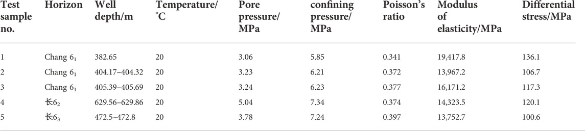
TABLE 1. Test results of rock mechanical parameters in Zhengzhuang block.
3.2 Calculation of in-situ stress profile of the reservoir
There are usually two methods to obtain in-situ stress data, one is an in-situ stress test, and the other is through calculation. The in-situ stress test is a direct means to obtain in-situ stress data. Its precision is high, but the test cost is high, and the measurement data is limited. The key to in-situ stress calculation is to establish a mechanical mathematical model suitable for the reservoir geological model and make full use of a large amount of information provided by logging data to conveniently and quickly obtain in-situ stress profiles continuously distributed along with the depth.
In situ stress is a very important basic parameter for fracture pressure calculation and fracturing optimization design. Here, a three-dimensional in-situ stress model is adopted. For the determination of vertical stress, the commonly used mode of vertical stress equal to overburden pressure is adopted. Overburden pressure is the pressure generated by the total weight of rock and pore fluid. It is usually expressed in the form of equivalent density, which is called the pressure gradient of overlying strata, and its change curve with depth is called the pressure gradient curve or profile of overlying strata. The pressure gradient of overlying strata mainly depends on the variation of rock mass density with well depth. The pressure gradient of the overlying strata is different in different areas.
The formula for calculating overburden pressure using density logging data is as follows.
Where: σv is the vertical stress at well depth h, MPa; ρ (h) is the density of overlying rock mass varying with depth, kg/m3; h is the well depth, m.
The horizontal principal stress is related to the formation pore pressure, the skeleton stress, and the tectonic stress in two directions on the horizontal plane. It is assumed that the rock is a homogeneous and isotropic linear elastomer and that there is no relative displacement between the stratum and the stratum in the process of sedimentation and later geological tectonic movement, and the strains in both horizontal directions of all strata are constant. From the generalized Hooke’s Law:
According to the above calculation method and logging data, the stress of the Chang 6 production interval is shown in Table 2, 3. The calculation results show that the stress difference of the Chang 6 production interval in the study block is less than 2 MPa, the stress difference of the reservoir interval is small, and the probability of longitudinal fracture penetration is large. During the fracturing process of horizontal wells, artificial fractures are easy to penetrate the layer vertically, which improves the reservoir reconstruction volume.
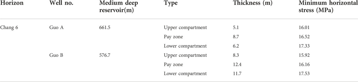
TABLE 2. Basic parameters of horizontal stress of production interlayer.
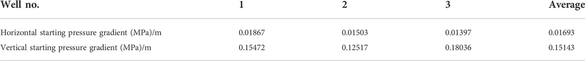
TABLE 3. Calculation of starting pressure gradient of Chang 6 reservoir.
The in-situ stress direction of the Chang 6 reservoir in the study block is 70° to the northeast. The direction of the maximum horizontal principal stress matches the extension direction of the artificial fracture. The volume of the volume fracturing reservoir is large. To solve the problem of easy formation channeling during fracturing and vertically connect different flow units, and improve the reservoir production degree. The arch well design is adopted in the study block. The well has a certain curvature when extending in the horizontal direction, and multiple horizontal fractures can be pressed out during fracturing. This can avoid the phenomenon that horizontal wells are prone to channeling during fracturing, and can drill through different flow units, which is conducive to improving production (Figure 1).
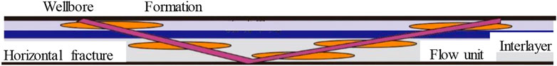
FIGURE 1. Development diagram of arch well with multiple horizontal fractures.
The horizontal fractures produced after the fracturing of bow-shaped horizontal wells are mostly circular and elliptical. Because the calculation of the elliptical fracture model is very complex, rectangular fractures are used in this paper. The rectangular model is approximately equal to the circular or elliptical fracture model in terms of parameters such as fluid flow and pressure distribution.
Multilayer fracturing horizontal fracture - when a horizontal fracture is produced by the fracturing of a bow horizontal well. Assuming that the length of the horizontal well is 2 L, the horizontal well is along the X axis, which divides the fracture plane into two. The fracture passes through the shaft of the near horizontal well, and
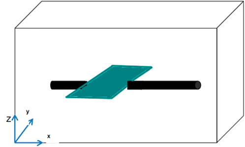
FIGURE 2. Schematic diagram of horizontal fracture space of fracturing in the horizontal well section.
Assuming that the reservoir thickness is h, the formation compressibility coefficient is unchanged, and the fluid is a slightly compressible fluid with constant viscosity and compressibility coefficient, ignoring the influence of the gravity field. The near horizontal well section has infinite conductivity, that is, there is no pressure drop in the near horizontal well section. The simplified physical model of horizontal fracture near the horizontal well is shown in Figure 3.
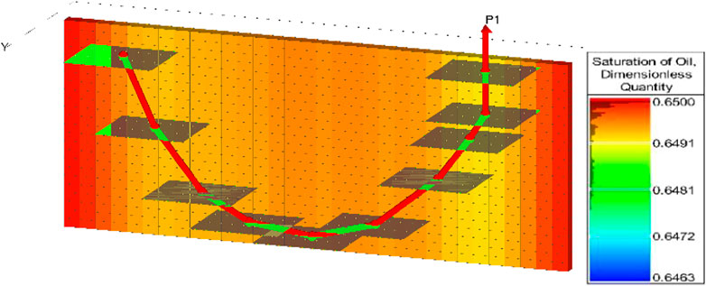
FIGURE 3. Simulation of bow horizontal well with horizontal fractures.
3.3 Demonstration of horizontal well pattern and well spacing
3.3.1 Formation pressure distribution of horizontal well
According to Lord Kelvin’s point source solution (Kelvin, 1884), the instantaneous point source function of a homogeneous reservoir is:
According to the superposition of countless isomorphic point sources corresponding to the top bottom closed reservoir vertically, the basic solution of the instantaneous point source of the top bottom closed reservoir is:
Using the properties of the series function, Poisson superposition formula, Laplace transform, and other methods, the basic solution of an instantaneous point source in the top bottom closed reservoir can be abbreviated as:
By integrating the basic solution along the wellbore direction, the corresponding mathematical model of the bottom hole pressure response can be obtained. For a vertical well, assuming that the length of the vertical well is
Suppose that the oil well bore produces at a constant flow rate, and the well is located at the center of the fracture
Derivation of Lord Kelvin point source solution (King, 2010; Chang, 2013; Wellhoefer et al., 2014), using the series function properly, Poisson superposition formula, Laplace transform, and other methods to simplify, the basic solution of the instantaneous source function of the top-bottom top-bottom reservoir is:
Assuming the length of the horizontal well is
The Laplace solution of the bottom hole pressure response function of the volume fracturing horizontal well can be obtained by integrating the formation pressure calculation formula of the horizontal well in the Y direction:
The bottom hole pressure response function calculation model of the horizontal well in the top-bottom top-bottom reservoir is established, and the infinite formation pressure distribution plan is defined, as is shown in Figure 4. The formation pressure of the horizontal well is elliptical in the near well zone and radial in the far well zone. The pressure drop mainly occurs within 50 m from the bottom of the well. The formation pressure of the fractured horizontal well is elliptical in the near well zone and radial in the far well zone, as is shown in Figure 5. The effective displacement pressure system of horizontal well and volume fracturing well is demonstrated by using the formation pressure calculation formula of horizontal well and volume fracturing well, combined with the potential superposition theory.
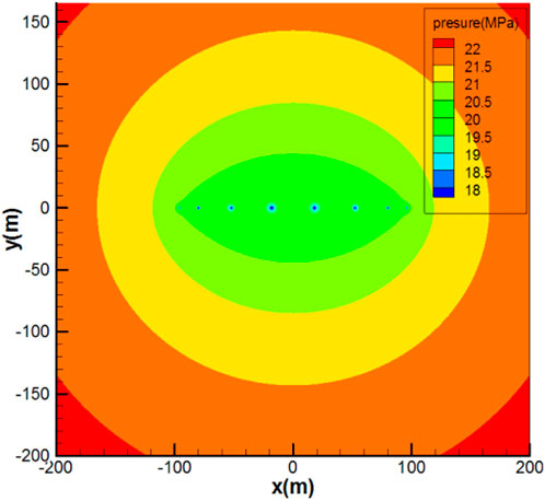
FIGURE 4. Formation pressure distribution near horizontal wells.
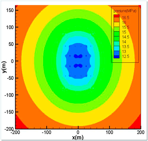
FIGURE 5. Formation pressure distribution plan near volume fracturing horizontal well.
3.3.2 Formation pressure distribution
Formation fluid can flow only when the pressure gradient is greater than a certain critical value, and this critical value can flow. This critical value is called starting pressure gradient, and this effect is called the low-speed non-Darcy effect.
The velocity equation considering the starting pressure gradient is:
Calculation of starting pressure gradient in low and extra low permeability reservoirs is as follows in Figure 6. The relationship between starting pressure gradient and permeability in the work area is:
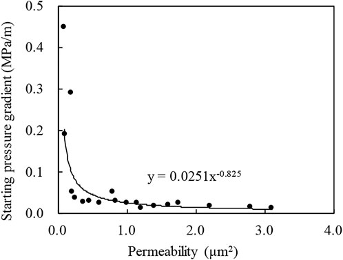
FIGURE 6. Relationship between reservoir permeability and starting pressure.
In combination with the relationship between starting pressure gradient and permeability, according to the formation pressure distribution functions of fractured well, horizontal well, and volume fractured horizontal well, and using the potential superposition theory, the formation pressure distribution calculation functions of the fractured well horizontal well (Figure 7) and fractured well volume fractured horizontal well (Figure 8) are compiled. The horizontal pressure distribution maps of a vertical well horizontal well, fracturing well horizontal well, and fracturing well volume fracturing horizontal well are drawn, and the relationship between different well spacing and start-up pressure gradient is obtained. Combined with the existing relationship between start-up pressure gradient and permeability in the work area, reasonable well spacing under different well types and different permeability is obtained. The starting pressure gradient in the work area is 0.05 mPa/m, the limit well spacing between fracturing and mental well is determined to be 150 m, and the limit well spacing between fracturing and volume fracturing horizontal well is determined to be 190 m.
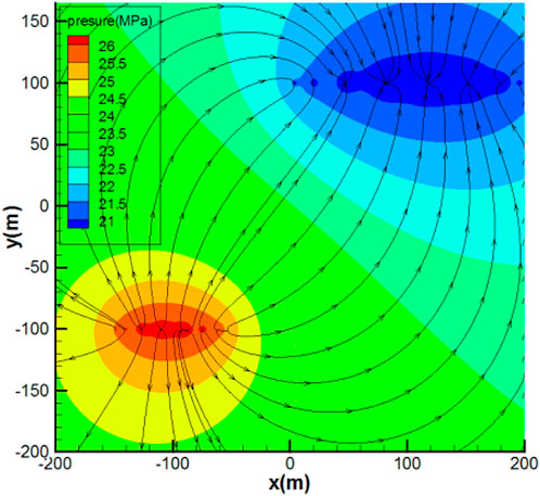
FIGURE 7. Plan of formation pressure distribution law of fracturing well horizontal well joint arrangement.
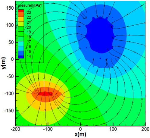
FIGURE 8. Formation pressure distribution plan of fracturing well volume fracturing horizontal well.
4 Optimization of key parameters for volume fracturing of horizontal wells
The fracture network model is established by using the equivalent conductivity and multigrid encryption method. At the same time, the small-scale fracture network simulation method of “main fracture + SRV regional permeability” can be used to study the conductivity matching between secondary fractures, branch fractures, and main fractures.
4.1 Numerical simulation model of volume fracturing in horizontal well
During the development of a fractured horizontal fracture reservoir, there exists a three-phase fluid flow of oil, gas, and water. Fractures can be the main channel of fluid flow, and the reservoir matrix is the main reservoir space of formation fluid. It is assumed that the model meets the following conditions:
1) The pore zone and pressure fracture zone occupy different space areas; 2) Considering the oil, gas, and water phases, the percolation of each phase obeys Darcy’s law; 3) Rock micro compressibility and homogeneity; 4) The water component has no mass transfer effect with the oil phase; 5) Considering the influence of gravity and capillary force; 6) The compression crack is horizontal, and the crack closure effect is considered.
The fracture network model is established by using equivalent conductivity and a multi grimulti-gradation method. According to the characteristics of Chang 6 reservoir in Qilicun oilfield of China and well layout (Table 5). Uniform step size is adopted on the plane, and the mesh step size is 30 m × 30 m. The grid direction is East-West to ensure that the artificial crack is parallel to the grid direction. In consideration of the approximate treatment requirements of artificial fractures and horizontal shafts, the local artificial fractures and static areas are densified. The approximate width of artificial fractures is 1 m, and the conductivity of hydraulic fractures is 0.2 Dm.
Combined with the pore permeability and saturation parameters of the reservoir, select the reservoir location with high permeability, high porosity, and high oil saturation in the flow unit for fracturing. Refer to the data divided by the previous flow unit, and select the location with the best physical properties in the flow unit for fracturing. The specific location is shown in Table 4.

TABLE 4. Hydraulic fracture location data of bow horizontal well.
4.2 Calculation of oil well productivity
Assuming that a horizontal well is deployed in the center of a homogeneous circular formation with equal thickness, the fluid flow from the boundary to the wellbore in the formation will no longer be radial flow like a vertical well but will show more complex fluid flow characteristics. Ignoring the influence of capillary pressure, gravity, and elastic expansion, under the condition of steady flow, different calculation formulas are derived by Renand and Dupuy (1991),
Where,
Taking the distribution of reservoir seepage field in a fractured horizontal well as an example, as is shown in Figure 9. According to the geological characteristics of the study area and the well layout mode, the uniform step size is adopted on the plane, and the grid step size is 30 m × 30 m, the grid direction is east-west, ensuring that the artificial cracks are parallel to the grid direction. The reservoir thickness is 10 m, the production pressure difference is 2.7 MPa, the viscosity is 4.29 mPa·s, the horizontal section length is 650 m, the oil drainage radius is 150 m, the well diameter is 0.065 m, a is 960 m, the volume factor is 1.05 after the production is stable, it is 6.0 t/d, and 6.5 t/d is calculated according to the improved formula.
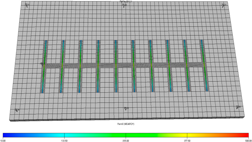
FIGURE 9. Optimization seepage model of key parameters of horizontal well volume fracturing.
4.3 Optimization of fracture parameters for volume fracturing of horizontal wells
To study the optimal matching of hydraulic fractures, the physical parameters required by the model are set according to the physical properties of the reservoir in the block, and the numerical simulation of oil well productivity under different lengths, segments, and half, length of fractures of horizontal wells is carried out.
TABLE 5. Setting of simulation parameters.
4.3.1 Length of horizontal section
The reservoir seepage field model of horizontal well after staged fracturing is obtained by numerical simulation, the pure blue represents the original permeability of the reservoir, the gradual red color represents the increase of reservoir permeability caused by fracturing, and the red represents the optimal conductivity after fracturing. The length of the horizontal well is an important factor affecting the productivity of the oil well. The Four situations are designed, i.e., the length of the horizontal well is 300, 500, 700, and 900 m, respectively, and the fracturing segments of horizontal wells are 3, 5, 7, and 9, respectively, as is shown in Figure 10. Eclipse is used to simulate the above schemes.
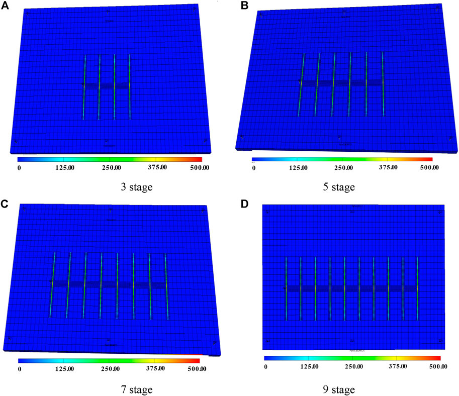
FIGURE 10. Influence of different horizontal well length on reservoir seepage field.
The continuous production of horizontal wells is predicted for 1 year. The prediction results show that with the increase in the length of horizontal wells, the cumulative production of oil wells gradually increases. When the length of the horizontal well exceeds 900 m, the increment of production will decrease. Therefore, the optimal length of a horizontal well in this area is recommended to be 900 m.
It can be seen from Figure 11 that the cumulative oil production in 1 and 2 years increases with the increase of horizontal section length of bow shaped well, but it is not a simple linear relationship. At first, the cumulative oil production increases rapidly with the increase of horizontal section length of bow shaped well, and then slowly decreases. When the length of arcuate well exceeds 900 m, the cumulative oil production curve has an obvious inflection point. Considering that the increase of the length of the water horizontal section will help to improve the productivity, but the drilling and completion cost will rise accordingly, so there is an optimal value, and the optimal value in this study is 900 m.
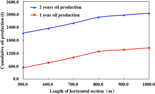
FIGURE 11. Cumulative oil production of different bow horizontal section lengths in 1 and 2 years.
4.3.2 Spacing of hydraulic fractures
The optimization of the distance between the staged fracturing of horizontal wells is the key to the success of the staged fracturing of horizontal wells. Assuming that the length of the horizontal well is 900 m, four modes of fracturing 6, 7, 8, and 10 are designed respectively, and the numerical simulation models of the above four modes are established by using eclipse numerical simulation software (Figure 12).
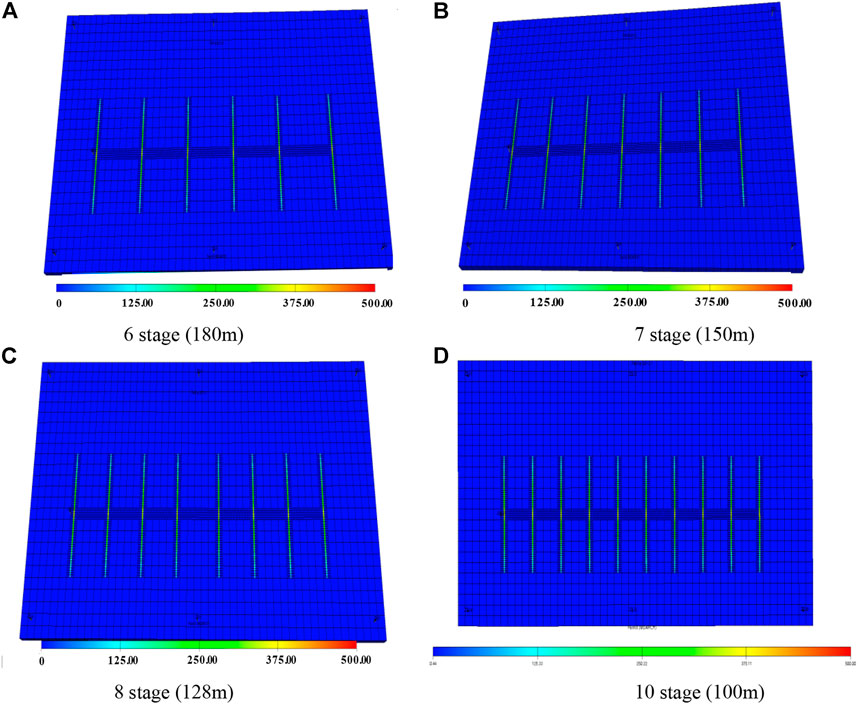
FIGURE 12. Influence of different interval distances on reservoir seepage field.
It can be seen from the simulation results that the number of fractures in horizontal wells affects the final production effect of horizontal wells. With the increase in fracture interval, the cumulative oil production of the oil well increases. However, due to the limited well control range of horizontal wells, when the fracture density increases to a certain value, the production increment will decrease, and too small the fracture spacing will produce serious inter-fracture interference.
According to the simulation results (Figures 13, 14), at first, the cumulative oil production of bow type wells increases with the increase of production time and the number of fractures, but when the number of fractures increases to 8, the cumulative oil production appears an inflection point, and the increase is obviously slower. The reason is that after the fracture spacing becomes smaller, the mutual interference increases, which reduces the output of a single fracture. The increase of fracturing fracture will lead to the increase of fracturing process cost, so the number of fractures has an optimal value. Therefore, it is suggested that the optimal fracture interval of horizontal wells is 120–130 m/interval, which means that the optimal number of fracturing fractures in horizontal well is 8.
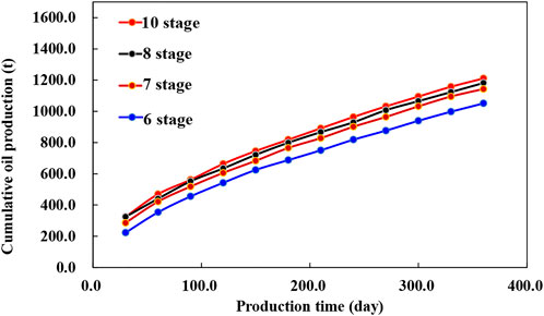
FIGURE 13. Relationship between fracture spacing and cumulative oil production.
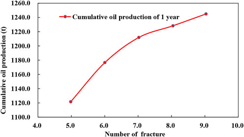
FIGURE 14. Relationship between the number of fracturing fractures and cumulative oil production.
4.3.3 Half-length of hydraulic fractures
Fracture half-length is a key parameter for volume fracturing of horizontal wells. The shorter the fracture half-length, the lower the fracture penetration ratio and the lower the multiple ratios of horizontal wells; The longer the half-length of the fracture, the higher the fracture penetration ratio, and the higher the multiple production ratio of the horizontal well, but the greater the possibility of water channeling in the water injection well, Therefore, using eclipse numerical simulation software, the fracture half-length optimization schemes with fracture half-length of 40, 60, 80, and 100 m are simulated (Figure 15). The longer the half-length of the fracture, the higher the production multiplier ratio of the horizontal well, which is more beneficial to the production of the oil well. However, the longer the half-length of the fracture, the greater the penetration ratio, and the easier the water channeling of the horizontal well, resulting in violent water flooding. The prediction results show that when the effective half-length of the horizontal well fracture reaches 90 m, the cumulative oil production of the horizontal well is the highest. It is suggested that the half-length of staged fracturing fracture of a horizontal well is 80–90 m.
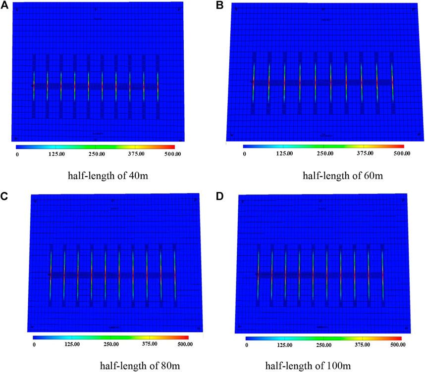
FIGURE 15. Influence of different fracture half-lengths on reservoir seepage field.
It can be seen from the analysis in Figure 16 that the cumulative production of the bow shaped horizontal well with multiple horizontal fractures increases with the increase of the fracture half length, but when the fracture half-length is 80m, the increase of the cumulative oil production curve narrows. At the same time, considering the fracturing cost, there is an optimal value. The half-length of the crack is preferably 80 m.
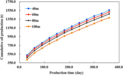
FIGURE 16. The cumulative production of bow shaped horizontal well with half lengths of horizontal fracture.
5 Conclusion
1) The rock mechanics test shows that the horizontal principal stress difference is small, the rock brittleness index is high, and the transverse sweep width of the joint network is large. The artificial fracture is matched with the horizontal wellbore, and the probability of longitudinal fracture penetration is large. Therefore, large-scale network fracture fracturing in horizontal wells is feasible.
2) The pressure response functions of horizontal well and volume fracturing horizontal well are established by using the point source function. Combined with the pressure superposition principle, the formation pressure plane distribution and flow line diagrams of fracturing horizontal well is drawn.
3) The distribution function of reservoir in-situ stress and formation pressure is established, and the relationship between reservoir permeability and starting pressure gradient in the block is calculated. The reservoir productivity equation of the block is established, which provides a basis for optimizing the fracturing design parameters of horizontal wells. It is proposed that the flow unit should be considered in the design of fracturing parameters of horizontal fractures, the number of fractures should be comprehensively considered whether the fractures can make each flow unit used. The seepage mathematical model of multi-layer fracturing horizontal fracture bow horizontal well can be regarded as the combination of multiple horizontal fracture flow units.
4) The fracture network model is established by using equivalent conductivity and multi-gridthod, and the volume fracturing design parameters of horizontal wells are optimized, considering the seepage characteristics of the flow unit. The simulation results show that the optimal length of the horizontal well is 800 m, the optimal fracture interval is 120 m/segment, and the optimal half-length of fracture is 80–90 m, which can improve the reservoir development effect.
Data availability statement
The raw data supporting the conclusion of this article will be made available by the authors, without undue reservation.
Author contributions
We confirm that the manuscript has been read and approved by all named authors and that there are no other persons who satisfied the criteria for authorship but are not listed. We further confirm that the order of authors listed in the manuscript has been approved by all of us. We understand that MW is the sole contact for the Editorial process. MW is responsible for communicating with the other authors about progress, submissions of revisions, and final approval of proofs. CG and MW: Conceptualization Formal analysis, Writing an original draft, Project administration, funding acquisition. SC: Software, Methodology, writing original draft, Writing-review, editing. WW, XM, SL, and ZG: Project administration, Formal analysis, Data curation.
Funding
This work was supported by the support of the National Natural Science Foundation of China: Study on dynamic characteristics of methane/carbon dioxide in shale heterogeneous reservoir under multi-field coupling (Program No. 41772150).
Conflict of interest
CG was employed by Yanchang Oil Field Co., LTD. WW was employed by Southwest Oil and Gas Field Company of CNPC Chengdu. ZG and XM were employed by Technology and Information Management Department of Yanchang Oilfield Co., Ltd. SL was employed by Engineering Research Institute of PetroChina Southwest Oil and Gasfield Company
The remaining authors declare that the research was conducted in the absence of any commercial or financial relationships that could be construed as a potential conflict of interest.
Publisher’s note
All claims expressed in this article are solely those of the authors and do not necessarily represent those of their affiliated organizations, or those of the publisher, the editors and the reviewers. Any product that may be evaluated in this article, or claim that may be made by its manufacturer, is not guaranteed or endorsed by the publisher.
References
Brice, L., and Jean, D. (2015). Simultaneous initiation and growth of multiple radial hydraulic fractures from a horizontal wellbore. J. Mech. Phys. Solids 82, 235–258. doi:10.1016/j.jmps.2015.05.010
Bunger, A. P., Zhang, X., and Jeffery, R. G. (2011). “Parameters affecting the interaction among closely spaced hydraulic fractures,” in SPE 140426, SPE hydraulic fracturing technology conference and exhibition (Woodlands, TX, USA, 24–26.
Chang, X. (2013). Fracture propagation in shallow tight reservoirs of Fuxian Block. Pet. Drill. Tech. 41, 109–113. (In Chinese).
Dohmen, T., Zhang, J., and Blangy, J. P. (2014). “Measurement and analysis of 3D stress shadowing related to the spacing of hydraulic fracturing in unconventional reservoirs,” in SPE annual technical conference and exhibition, Amsterdam, Netherlands, October 2014.
Du, G. C., Hu, S. Q., Shi, L. H., Wei, F., et al. (2015). Reservoir characteristics and pore evolution of Chang 6 oil reservoir set in Qilicun Oilfield. Lithol. Reserv. 27, 51–57. (In Chinese).
El Rabba, W. (1989). “Experimental study of hydraulic fracture geometry initiated from horizontal wells,” in SPE annual technical conference and exhibition. San Antonio, TX, USA.
Hillerborg, A., Modeer, M., and Petersson, P. E. (1976). Analysis of crack formation and crack growth in concrete by means of fracture mechanics and finite elements. Cem. Concr. Res. 6 (6), 773–781. doi:10.1016/0008-8846(76)90007-7
Jiang, T. X., Wang, H. T., Bian, X. B., Li, H., Liu, J., Wu, C., et al. (2018). Volume fracturing technology for horizontal well and its application. Lithol. Reserv. 30, 1–11. (In Chinese).
Kazemi, H. (1982). Low-permeability gas sands. J. Petroleum Technol. 34 (10), 2229–2232. doi:10.2118/11330-PA
King, G. E. (2010). “Thirty years of gas shale fracturing: What have we learned?,” in SPE annual technical conference and exhibition, Florence, Italy, September 2010.
Li, Y., He, Q., Yao, C., Zhang, Y., Wang, X., et al. (2013). Discussion on fracture morphology of shallow layer fracturing in the south of Ordos basin. Petroleum Geol. Eng. 27, 105–107. (In Chinese).
Li, K., Chen, G., Li, W., Wu, X., Tan, J., and Qu, J. (2018). Characterization of marine-terrigenous transitional Taiyuan formation shale reservoirs in Hedong coal field, China. Adv. Geo-Energy Res. 2 (1), 72–85. doi:10.26804/ager.2018.01.07
Li, C., Singh, H., and Cai, J. (2019). Spontaneous imbibition in shale: A review of recent advances. Capillarity 2 (2), 17–32. doi:10.26804/capi.2019.02.01
Meng, X. G., Yuan, Y. J., and Dai, X. X. (2014). Characteristics of Chang 6 reservoir in Y49 region, Qilicun oilfield. Liaoning Chem. Ind. 43, 791–793. (In Chinese).
Mokryakov, V. (2011). Analytical solution for propagation of hydraulic fracture with Barenblatt’s cohesive tip zone. Int. J. Fract. 169, 159–168. doi:10.1007/s10704-011-9591-0
Mutalik, P. N., and Gibson, B. (2008). “Case history of sequential and simultaneous fracturing of the Barnett shale in parker county,” in SPE annual technical conference and exhibition, Denver, Colorado, September 2008.
Rafiee, M., Soliman, M. Y., and Pirayesh, E. (2012). “Hydraulic fracturing design and optimization: A modification to zipper frac,” in SPE 159786, presented at the SPE eastern regional meeting (Kentucky, USA.
Renand, G., and Dupuy, J. M. (1991). Formation damage effects on horizontal well flow efficiency. JPT 7, 786–789.
Sesetty, V., and Ahmad, G. (2015). A numerical study of sequential and simultaneous hydraulic fracturing in single and multi-lateral horizontal wells. J. Petroleum Sci. Eng. 132, 65–76. doi:10.1016/j.petrol.2015.04.020
Somanchi, K., Brewer, J., and Reynolds, A. (2017). “Extreme limited entry design improves distribution efficiency in plug-n-perf completions: Insights from fiber-optic diagnostics,” in SPE hydraulic fracturing technology conference and exhibition.
Su, H., Lwi, Z., Zhang, D., Li, J., Ju, B., and Zhang, Z. (2018). Volume fracturing parameters optimization of horizontal well in tight reservoir. Lithol. Reserv. 30, 140–148. (In Chinese).
Su, G., Han, Q., Ma, X., and Wang, L. (2018). Study and application of the stimulated reservoir volume fracture technology in dense gasfield. Petrochem. Ind. Appl. 37, 74–76. (In Chinese).
Su, Y., Wang, B., Xu, N., Zhang, Z., Liu, Y., and Hou, J. (2020). Discussion on energy storage fracturing technology of Chang X tight reservoir in block A of Dingbian area. Petrochem. Ind. Appl. 39, 62–65. (In Chinese).
Wang, H., Marongiu-Porcu, M., and Economides, M. J. (2016). Poroelastic and poroplastic modeling of hydraulic fracturing in brittle and ductile formations. Paper SPE 168600-PA. SPE Production & Operations 31 (1), 47–59.
Wang, H. (2016). Numerical investigation of fracture spacing and sequencing effects on multiple hydraulic fracture interference and coalescence in brittle and ductile reservoir rocks. England: Eng. Fract. Mech. 157, 107–124. doi:10.1016/j.engfracmech.2016.02.025
Wang, X. J., Tang, H., She, L., Zou, G., Zhou, J., Li, X., et al. (2014). Optimization of fracture parameters of horizontal well in low permeability reservoir. Lithol. Reserv. 26, 129–132. (In Chinese).
Wellhoefer, B. J., Eis, A., and Gullickson, G. W. (2014). “Does a multi-entry, multi-stage fracturing sleeve system improve production in Bakken Shale wells over other completion methods?,” in SPE/CSUR unconventional resources conference.
Weng, X., Kresse, O., Cohen, C. E., Wu, R., and Gu, H. (2011). Modeling of hydraulic fracture network propagation in a naturally fractured formation. SPE Prod. Operations 26 (4), 368–380. doi:10.2118/140253-pa
Westwood, R. F., Toon, S. M., Styles, P., and Cassidy, N. J. (2017). Horizontal respect distance for hydraulic fracturing in the vicinity of existing faults in deep geological reservoirs: A review and modelling study. Geomech. Geophys. Geo. Energy. Ge. Resour. 3, 379–391. doi:10.1007/s40948-017-0065-3
Xiong, J., Wang, S. P., and Guo, P. (2012). Study on the production-increasing law of the horizontally fractured wells in low-permeability reservoirs. Special Oil Gas Reservoirs 19, 101–103. (In Chinese).
Xiong, Y., Zhang, L., Zhao, Y., and Liu, Q. (2014). Pressure transient analysis of hydraulic fractured vertical well in stress-sensitive shale gas reservoirs. Sci. Technol. Eng. 14, 221–225.
Xiong, H. J., Liu, S. X., Feng, F., Liu, S. A., and Yue, K. M. (2020). Optimizing fracturing design and well spacing with complex-fracture and reservoir simulations: A permian basin case study. SPE Prod. Operations 35 (04), 0703–0718. doi:10.2118/194367-pa
Xu, Y., Chen, M., Wu, Q., Li, D. Q., Yang, N. Y., Weng, D. W., et al. (2016). Stress interference calculation model and its application in volume stimulation of horizontal wells. Petroleum Explor. Dev. 43 (5), 849–856. doi:10.1016/s1876-3804(16)30101-x
Xu, J., Wu, K., Li, R., Li, Z., Jing, L., Xu, Q., et al. (2018). Real gas transport in shale matrix with fractal structures. Fuel 219, 353–363. doi:10.1016/j.fuel.2018.01.114
Xu, J., Chen, Z., Wu, K., Li, R., Liu, X., and Zhan, J. (2019). On the flow regime model for fast estimation of tight sandstone gas apparent permeability in high-pressure reservoirs. Energy Sources, Part A Recovery, Util. Environ. Eff., 1–12. doi:10.1080/15567036.2019.1687625
Xu, J., Wu, K., Li, R., Li, Z., Li, J., Xu, Q., et al. (2019). Nano-scale pore size distribution effects on gas production from fractal shale rocks. Fractals 27 (8), 1950142. doi:10.1142/S0218348X19501421
Yang, H., Liang, X., He, H., Wang, D., Wang, J., et al. (2014). Study on the hydraulic fracture morphology in Yanchang oilfield. J. Chongqing Inst. Sci. Technol. 16, 9–11. (In Chinese).
Yew, C. H., and Weng, X. W. (2015). in Chapter eight- stress shadow (Boston: Gulf Professional Publishing), 177–195.
Yi, X. Y., Zhang, Z., Li, C. Y., Li, D. C., and Wang, S. B. (2013). “Well, test interpretation method of horizontal well in stress-sensitive gas reservoir,”. Applied mechanics and materials (Trans Tech Publications, Ltd), 295–298, 3183–3191.
Zhang, S., Wen, Q., Wang, F., Zhang, G., et al. (2004). Optimization design of integral fracturing parameters for a four-spot well pattern with horizontal fractures. Acta Pet. Sin. 25 (1), 74–78. (In Chinese).
Zhang, R., Li, L., Qi, L., and Luo, Y. (2015). Vertical well network fracturing technique policy argument in zhaoyuannan oilfield. Sci. Technol. Eng. 15, 29–35. (In Chinese).
Zhang, H., Meng, X. G., Shao, C. J., Dai, X., Yu, H., Li, X., et al. (2018). Forming mechanism and monitoring of horizontal hydraulic fracture:a case from Qilicun oilfield. Lithol. Reserv. 30, 138–145. (In Chinese).
Zhang, Y., Yan, Y., Liu, L., Gao, Y., and Zhao, S. (2020). Exploration and practice of extending the stage fracturing technology of horizontal wells in Yanchang oilfield. J. Yanan Univ. Nat. Sci. Ed. 39, 57–60. (In Chinese).
Keywords: Chang 6 reservoir, sandstone formation, volume fracturing, bow horizontal well, horizontal fracture
Citation: Gao C, Cheng S, Wang M, Wu W, Gao Z, Li S and Meng X (2023) Optimization of volume fracturing technology for shallow bow horizontal well in a tight sandstone oil reservoir. Front. Energy Res. 10:976240. doi: 10.3389/fenrg.2022.976240
Received: 23 June 2022; Accepted: 07 September 2022;
Published: 05 January 2023.
Edited by:
Debin Kong, University of Science and Technology Beijing, ChinaReviewed by:
Jinze Xu, University of Calgary, CanadaWenhui Song, China University of Petroleum, Huadong, China
Copyright © 2023 Gao, Cheng, Wang, Wu, Gao, Li and Meng. This is an open-access article distributed under the terms of the Creative Commons Attribution License (CC BY). The use, distribution or reproduction in other forums is permitted, provided the original author(s) and the copyright owner(s) are credited and that the original publication in this journal is cited, in accordance with accepted academic practice. No use, distribution or reproduction is permitted which does not comply with these terms.
*Correspondence: Mingwei Wang, MjAxOTk5MDEwMTM3QHN3cHUuZWR1LmNu