 Jian-Guang Wei1,2Xian-Jun Wang3Xiao-Fei Fu1,2Peng-Qi Gong4
 Xiao-Feng Zhou1,2*
 Yu-Wei Li5Ying Yang1,2Ying-He Chen6Bao Jia7Jie Wu8
- 1Key Laboratory of Continental Shale Hydrocarbon Accumulation and Efficient Development (Northeast Petroleum University), Ministry of Education, Northeast Petroleum University, Daqing, Heilongjiang, China
- 2Institute of Unconventional Oil and Gas, Northeast Petroleum University, Daqing, China
- 3Daqing Oilfield Limited Company, Daqing, China
- 4Greatwall Drilling Company, Beijing, China
- 5Liaoning University, Shenyang, China
- 6School of Petroleum Engineering, Northeast Petroleum University, Daqing, Heilongjiang, China
- 7CNPC Offshore Engineering Company Limited, Tianjin, China
- 8GWDC Drilling Engineering and Technology Research Institute, Panjin, China
For the purpose of cost management, many companies and research institutions have carried out technical research on the replacement of ceramic with quartz sand as proppant. However, few studies have systematically carried out short-term and long-term conductivity evaluation experiments for quartz sand proppants with different particle sizes. It is urgent to conduct experiments on the conductivity of quartz sand, and optimize the fracturing design based on the experimental results. The conductivity is the key indicator of the fracturing effect. The greater the conductivity, the better the hydraulic fracturing effect, and the longer the effective period, the higher the fracturing benefit. In this study, by evaluating the long-term conductivity of proppant, the influence of the type of quartz sand proppant, proppant particle size and sand paving concentration on the fracture conductivity are studied. Main results show that 1) the proppant performance of quartz sand produced in Chifeng is better than that of produced in Tongliao; 2) The long-term conductivity experiment results show that the conductivity of quartz sand proppant produced in Chifeng is better than that of TL, and under the same sanding concentration and closing pressure, the larger the particle size of the quartz sand, the higher the conductivity, and the greater the decrease in conductivity with the increase of the closing pressure; 3) In the influence of sand paving concentration, when the sand paving concentration is 5 and 7.5 kg/m2, the conductivity increase with the increase of the sand paving concentration.
1 Introduction
For the past decade, due to the unbalanced relationship of the great amount of conventional fuels’ consumption and the declining supply all over the world, unconventional oil and gas resources have received considerable interests due to its wide distribution and abundant reserves (Sun et al., 2022a; Yuwei et al., 2020). However, for unconventional oil and gas resources, due to the poor permeability of the reservoir matrix, there is almost no industrial oil and gas flow directly into production after drilling. Therefore, in order to economically and effectively develop aforementioned resources, multi-stage fracturing or volume fracturing combined with horizontal well are the most widely adopted method at present (Zhang T. et al., 2017; Yuwei et al., 2019; Fan et al., 2020). In the process of volume fracturing and multi-stage fracturing, it is inevitable that a very large amount of proppant will be used, in order to reduce the fracturing cost, many institutions and scholars have carried out the study of using quartz sand instead of ceramic as proppant (Herskovits et al., 2016; Kou et al., 2018; Su et al., 2020). At present, various oil companies and oil service companies in North America are working together to improve single well production and reduce well construction costs. Of that, drilling and completion costs ranged from four million to eight million dollars, with an average of 6.5 million dollars, and fracturing costs accounted for 60 percent. Moreover, in the cost of fracturing, the material cost account for a very important proportion, the cost of fracturing fluid and proppant account for 19% and 25% of the drilling and completion costs, respectively. Hence, the proppant, in particular, has become an important target for cost reduction (Syfan et al., 2013; Sun et al., 2022b).
For the past few years, oil companies in North America have adopted methods such as replacing ceramic with quartz sand and building nearby sand plants through technological and management innovations, which have greatly reduced the operating costs of hydraulic fracturing projects and boosted the economic and efficient development of unconventional oil and gas (Olmen et al., 2018; Ziyuan et al., 2022). Moreover, with the increase of horizontal section length, sanding intensity and the number of horizontal wells, the proppant consumption in North America increased from 1820 × 104t in 2010 to more than 1.09 × 10⁸t in 2018, the amount of proppant used in a single well has increased from 500t in 2010 to 5000t in 2019. At present, the proportion of quartz sand in proppant in North America has reached 96% (Olsen et al., 2009; Liang et al., 2015; Barree et al., 2018).
Ceramic and quartz sand proppant are the most used types of proppants in the field of hydraulic fracturing. Comparing to the quartz sand, ceramic proppant own higher hardness and sphericity, at the same time, its ensures a large fracture conductivity especially under the high effective closure stress condition (Zhang et al., 2016; Zhang F. et al., 2017; Srinivasan et al., 2018; Zhao et al., 2020). On the other side, ceramic proppants usually 3–5 times more expensive than quartz sand, also, they own larger densities which are unfavorable for the proppant transportation within the hydraulic fractures (Maity and Ciezobka, 2019; Feng et al., 2021; Huang et al., 2021). Some other researchers carried out 1-D compression test, step-wise creep tests, as well as displacement-controlled diametrical compression tests on single proppant grains, experimental results shows that individual ceramic proppants own higher time-independent crushing resistance than the quartz sand, but quartz sand proppant is more compressible compared with the ceramic proppant (Man and Wong, 2017; Fjaestad and Tomac, 2019; Tasqué et al., 2021; Sun et al., 2022c). Studied the influence of stress cycling on the performance of sand and ceramic proppant in thin pack/monolayer conditions, results shown that the mechanical performance were decreased for all the proppant samples under three and five cycles as compared to standard one cycle test, the sand proppant and ceramic proppant both shown a significant increase in crush with an increase in number of cycles. Moreover, the ceramic proppant appear to be more sensitive to stress cycling under thin layer/monolayer conditions. Hu et al. (2015) compared the effect of different proppants (sand, resin-coated sand, and ceramic proppant) on the long-term production through Bakken shale wells, their results revealed that the long-term production of wells completed with ceramic proppant significantly outperforms wells completed exclusively with other proppant types. Moreover, the resin-coated sand helped improve initial production but have no effect on long-term production. Studied the feasibility of natural sand proppant in deeper shale reservoirs through NPV study, and results indicated that the natural sand proppant have a much larger range of applicability than previously thought.
According to the above-mentioned literature survey and aware of possible limitations, the current research on quartz sand proppant is more focused on the comparison between quartz sand proppant and ceramic proppant. In reality, the natural quartz sand can be used as proppant in China are mainly distributed at Chifeng and Tongliao in Inner Mongolia, Luliang in Xinjiang, Anning in Lanzhou, et al. (Jia, 2011; Dong and Lv, 2017; Yuwei et al., 2017; Liang and Yan, 2021) In this study, we chose the quartz sand produced in Chifeng (CF) and Tongliao (TL) as the proppants. Firstly, the performance of quartz sand from different origins and different meshes were compared through experiments. Secondly, the long-term conductivity of quartz sand proppant produced in different area were investigated. Finally, the effects of sand paving concentration and closure pressure on long-term conductivity were studied. The main results are as follows: 1) for the proppant performance, quartz sand produced in Chifeng (CF) performs better; 2) The long-term conductivity experiment results show that the conductivity of quartz sand proppant produced in CF is better than that of TL, and under the same sanding concentration and closing pressure, the larger the particle size of the quartz sand, the higher the conductivity, and the greater the decrease in conductivity with the increase of the closing pressure; 3) In the influence of sand paving concentration, when the sand paving concentration is 5 kg/m2 and 7.5 kg/m2, the conductivity increase with the increase of the sand paving concentration. As the closing pressure increases, the decrease of conductivity of the flow decreases with the increase of the sand paving concentration.
2 Proppant performance evaluation test
In order to better compare the flow conductivity of quartz sand, it is first necessary to conduct performance evaluation experiments on quartz sand with different particle sizes and different producing areas. And the evaluation parameters include the following six items, density, acid solubility, crushing rate, sphericity, screen analysis, turbidity. Moreover, to compare above parameters, quartz from two producing areas, Chifeng (CF) and Tongliao (TL), China, was selected here, and three different mesh proppants were screened out, included 20–40, 40–70, 70–140, finally, this study compared the performance of six quartz proppants, which names CF 20–40, CF 20–40, CF 20–40, TL 20–40, TL 40–70, TL 70–140, here, CF 20–40 represents the proppant which produced in Chifeng, and the mesh number is 20–40 mesh.
2.1 Density evaluation
The experimental procedure of density evaluation is as follows: 1) Prepare appropriate proppant samples. 2) Prepare a 0.0001 g balance and a dry beaker, place the beaker on the balance, weigh out the mass of the beaker, and reset the balance to zero. 3) Slowly load the samples into the beaker, weigh out the beaker containing proppant, the reading of the balance is the mass of the proppant m. 4) Take a measuring cylinder with a range of 10 ml and add distilled water V1 into the measuring cylinder. 5) Pour the proppant in the beaker slowly into the measuring cylinder, and record the reading V2 of the measuring cylinder. 6) Repeat the above steps three times and take the average density. 7) Then the density of proppant equals:
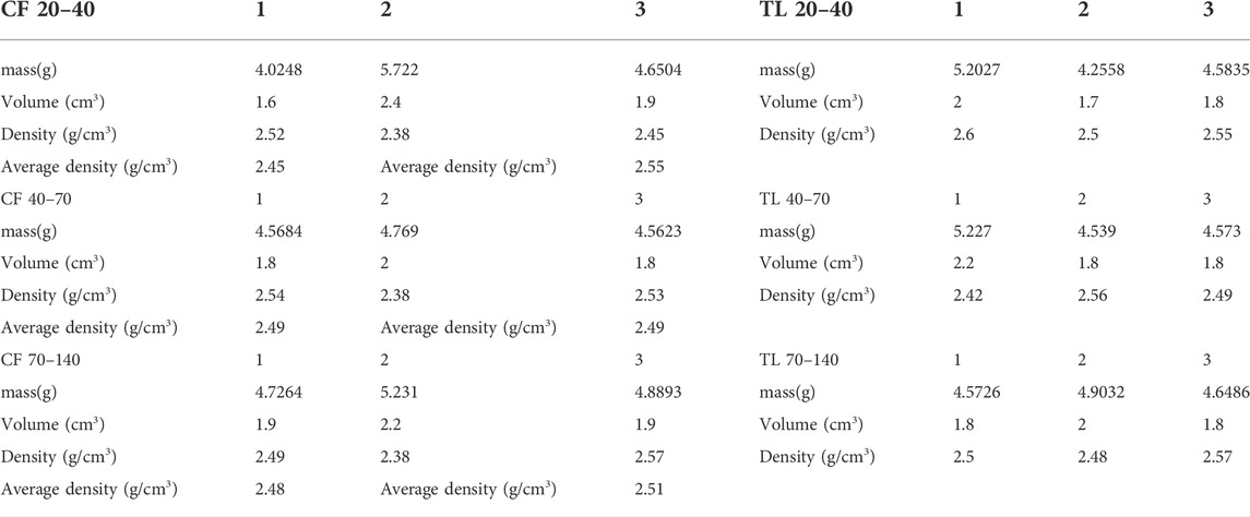
TABLE 1. The critical thickness of the interface region in different fluid-nanopore systems.
2.2 Acid solubility evaluation
The experimental procedure of acid solubility evaluation is as follows: 1) An appropriate amount of proppant sample was dried at 105°C for 1 h, then placed in a desiccator to cool for 0.5 h, and weighed. 2) Weigh 5±1 g of the above-mentioned processed proppant sample. 3) Add 106.6 g (100 ml in volume at 20°C) of the prepared mixed solution of hydrochloric acid and hydrofluoric acid into a 250 ml polytetrafluoroethylene (PTFE) beaker, then pour the weighed 5 g sample into the beaker. 4) The beaker containing the acid solution and proppant sample was placed in a water bath at 65°C at a constant temperature for 0.5 h. Be careful not to stir or contaminate it. 5) Preparing the filter equipment: put the qualitative filter paper in a PTFE funnel, dry it at 105°C for 1 h, then cool it in a desiccator for 0.5 h, weigh and record its quality, then place it on the vacuum filter device for later use. 6) Pour the proppant sample and acid solution into the PTFE funnel, make sure to pour all the proppant particles in the beaker into the funnel, and then perform vacuum filtration. 7) The proppant samples were rinsed with distilled water for 5 to 6 times, until the rinsing solution was neutral. 8) The PTFE funnel and its proppant samples were placed together in the oven to dry at 105°C for 1h, then put it in a desiccator to cool for 0.5 h 9) Weigh the cooled PTFE funnel and proppant sample together and record the mass, then the acid solubility of proppant samples is as follow:
Where S is the acid solubility of proppant samples. ms is the mass of proppant samples. mfp is the mass of PTFE funnel and filter paper. mfs is the mass of PTFE funnel, filter paper and sample after acid etching.
The acid solubility of six kinds of proppant sample are shown in Table 2.
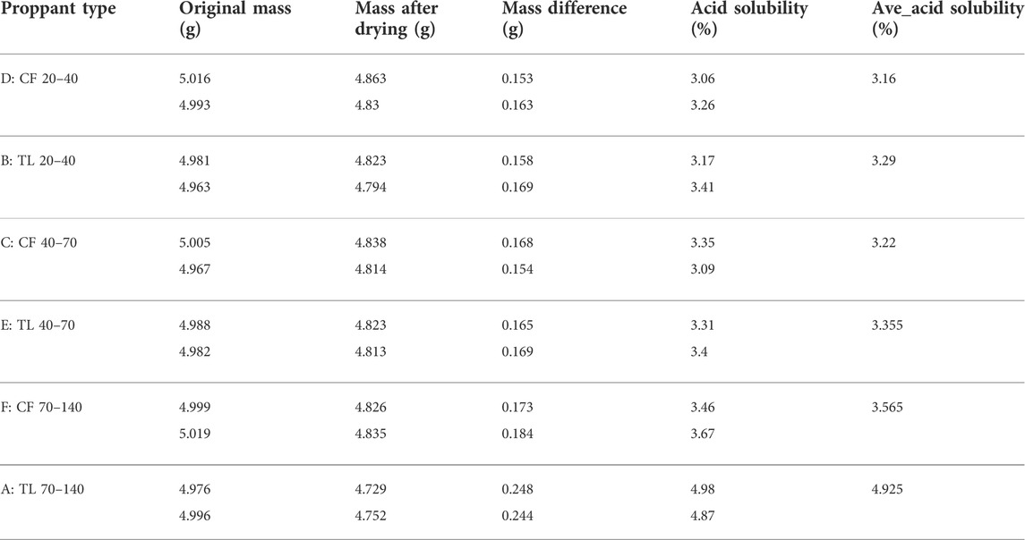
TABLE 2. Measurement of acid solubility of different proppants.
2.3 Crushing rate evaluation
The experimental procedure of crushing rate evaluation is as follows: 1) Based on the formula m = C1d2, in can be seen that the mass of the sample required for the anti-crushing experiment of quartz sand proppant is 89.42 g. 2) The sample is poured into the crushing chamber, and the rated load is added to the crushing chamber at a uniform speed with a constant loading time of 1min. After the load is stabilized for 2 min, the load is removed. 3) After screening the pressed proppant samples and weighing the crushed particle mass m1, the proppant crushing rate is: η = m1/m × 100%.
Figure 1 shows the comparison of the crushing rate of six proppants with the closure pressure. As it can be seen that with the closure pressure reaching 35 MPa, the crushing rate of all proppants have increased significantly, however, as the increase of mesh size of proppants, the magnitude of this increase gradually decreases. The crushing rate of the two types of quartz proppants decreases with the increase of the mesh number. At the same time, the proppant crushing rate of CF is lower than that of TL, and its crushing rate is about 20%–40% lower. Therefore, it can be concluded that the proppant produced in CF has better anti-crushing rate than the proppant produced in TL.
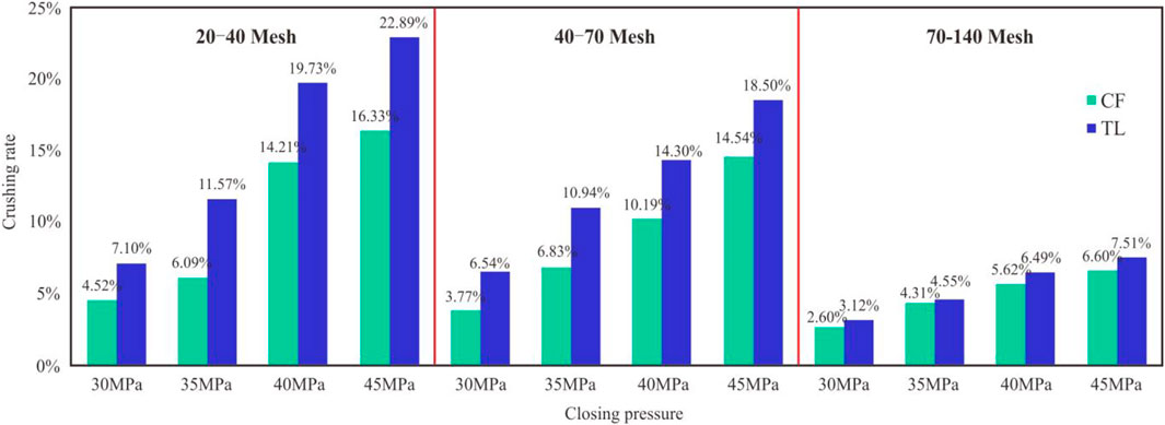
FIGURE 1. Comparison of crushing rate of each proppant with closure pressure.
2.4 Sphericity evaluation
The test of proppant sphericity is carried out through the proppant sphericity and roundness chart. The test method is to randomly take out 20–30 proppants from the tested proppant samples, observe it under the microscope, and take the photomicrograph, then the sphericity and roundness of each proppant was determined. Finally, calculate the average sphericity of this batch of proppant products. Figure 2 shows the sphericity test results of each proppant, it can be seen that the difference in sphericity of proppants with different meshes from two production area is small, and the degree of regularity is similar.
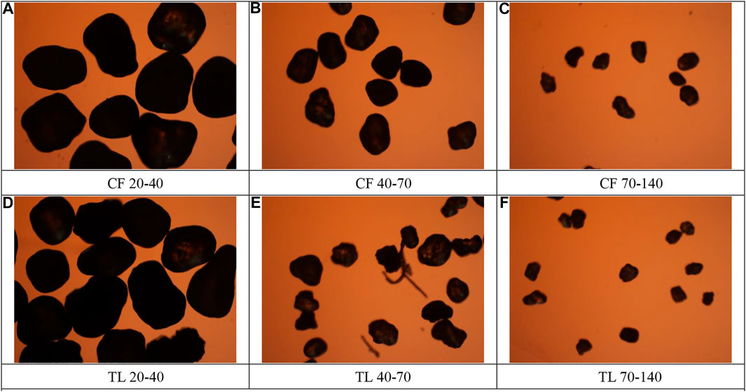
FIGURE 2. Microscope picture of each proppant under the microscope.
2.5 Screen analysis evaluation
The screen analysis of proppant is to examine the size (particle size range), particle size composition (particle size distribution) and the average particle size of the proppant, the experimental procedures for sieve analysis and evaluation are as follows: 1) Screening preparation: Seven sieves are stacked on top of each other, a series of sieves plus a bottom plate and a cover, the aperture size of these sieves gradually decreases from top to bottom. Divide the sample into 80–120 g, weigh each sieve and record the sieve weight. 2) Sieve analysis: Pour the weighed sample to be tested from the top layer of the standard sieve, cover the lid and fix it on the sieve shaker, and take it out after shaking the sieve for 10 min. Weigh the material in each sieve and plate and record the results, and calculate the percentage of the total proppant sample mass remaining in each sieve and pan. The cumulative mass should be within 0.5% of the mass of the sample used in the experiment. 3) The average diameter of proppant is calculated by the following equation:
Where dav is the average diameter of proppant, d is the mean particle size, and n is the frequency of occurrence.
Figure 3 shows the histogram of average diameter comparison of screen analysis, it can be seen that the average diameter of proppant produced in CF is larger than that in TL. Obviously, when the proppant filling the fracture, the higher the proportion of large particle size proppant, the more gaps between the particles, and corresponding greater fracture permeability. Therefore, for the proppants from CF and TL, the fracture permeability with the proppant from CH will be higher.
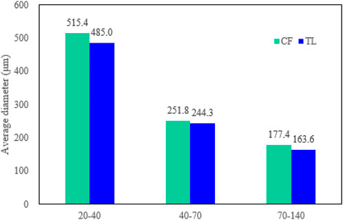
FIGURE 3. Average diameter contrast of screen analysis.
2.6 Turbidity evaluation
For proppants, high concentrations of dust, mud, and inorganic impurities on the surface of the proppant particles will block the pores between the particles during construction process, reducing the flow capacity of the fluid, and ultimately affecting the conductivity of propping fractures. The test method is to pour a certain quality of proppant into a certain volume of distilled water, shake it with a certain number of times within a specified period of time as required and leave it for a period of time to detect the content of impurities in the liquid. The experimental procedures for turbidity evaluation are as follows: 1) Preparation of sample liquid. Put 40.0 g of sample proppant into a 250 ml jar, pour 100 ml of distilled water into the jar, let it stand for 30 min, shake it horizontally for 0.5 min, 60 times, and leave it for 5 min 2) Measurement. Before the turbidity test, preheat the instrument for a period of time, and use the standard turbidity board to adjust the instrument to the factory zero. Then use a medical syringe to extract part of the liquid to be tested on the wall of the container, pour it into a cuvette according to the specified volume requirements, put it into the turbidimeter for measurement, and read the test result.
Figure 4 shows the comparison of turbidity test results, it can be seen that the turbidity of 20–40 mesh and 70–140 mesh in CF producing area is less than that in TL producing area, and the 40–70 mesh proppant in CF producing area is slightly larger than that in TL producing area. Therefore, CF 20–40 mesh, 70–140 mesh proppant surface dust, mud, and inorganic impurities content is less, it is not easy to block the pores and reduce permeability. On the other hand, CF 40–70 mesh proppant has higher impurity content, which tends to block pores and reduce permeability.
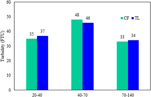
FIGURE 4. Comparison of turbidity test results.
Based on the above-mentioned six quartz sand of proppant performance experiments analysis, it can be known that the proppant produced in CF is better than the proppant produced in TL.
3 Optimization of long-term conductivity of quartz sand proppant
3.1 Long-term conductivity experimental process
After the performance evaluation of quartz was completed, it began to conduct experimental research on the long-term conductivity of different quartz sand proppants. The specific experimental steps are as follow:
1) Confirm the initial zero point, assemble the empty diversion chamber, and place it between the two parallel plates of the hydraulic frame. Open the hydraulic press inlet valve and shut-off valve (the return valve should be closed), run the hydraulic press, and lift the lower plate until the cylinder pressure reaches 10 MPa to stop. Use the software to record the reading of the displacement sensor, which is the initial zero point (the displacement sensor should be installed vertically), remove the closing pressure, remove the diversion chamber, and remove the upper piston and upper cover.
2) Fill the proppant. Put the bottom piston with the sealing ring into the diversion chamber, place a piece of metal plate on the bottom piston (must be flat), pour the weighed proppant into the diversion chamber, and use a scraper to smooth the proppant. Put another piece of metal plate on the surface of the flattened proppant, put the upper piston with the sealing ring into the diversion chamber, and connect the quick joints of the inlet and outlet connected with the diversion chamber.
3) Open valve 6, turn on the vacuum pump to vacuum for 5 min, turn off the vacuum pump, close valve 6, and vent the vacuum pump.
4) Open valves 3 and 4, suck distilled water from the beaker filled with distilled water, open valves one and two to empty the differential pressure sensor, and then close valves 1, 2, 3, and 4.
5) Open valves 5 and 7, adjust the parameters, open the intermediate container and advection pump after the closed pressure stabilizes, record the experimental data, and start the experiment.
The schematic diagram of conductivity experimental device is shown in Figure 5.
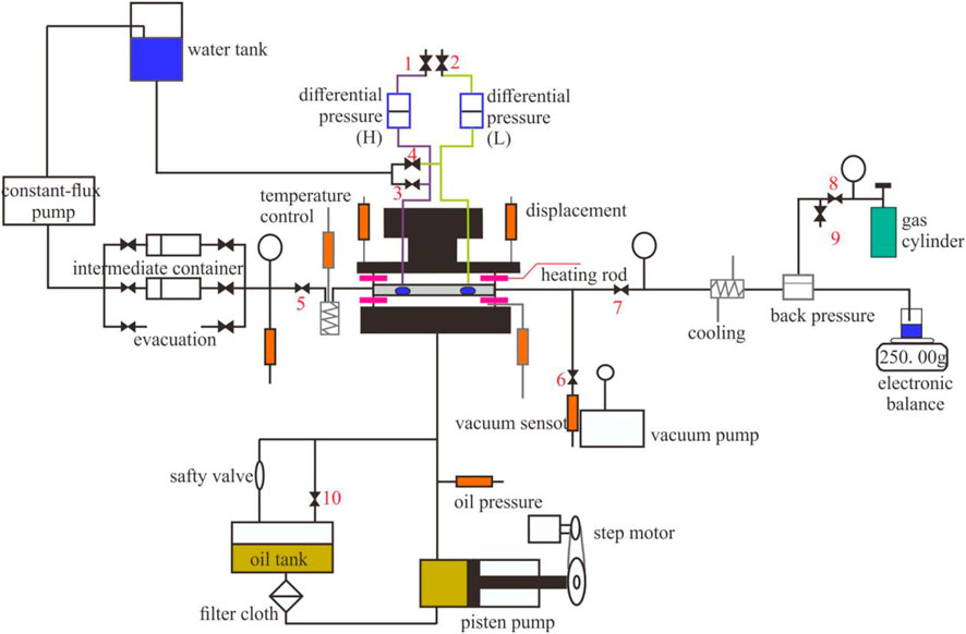
FIGURE 5. Schematic diagram of conductivity experiment device.
3.2 Long-term conductivity experimental results
Firstly, by comparing the conductivity of CF 20–40 proppant and TL 20–40 proppant, apparently that the proppant produced in CF is better than the proppant produced in TL. From Figure 6 it can be seen that the conductivity of proppant of CF 20–40 is 9.48% higher than that of TL 20–40 while the closing pressure is 30 MPa, the conductivity of proppant of CF 20–40 is 8.76% higher than that of TL 20–40 while the closing pressure is 35 MPa, and when the closing pressure reaches 40 and 45 MPa, the conductivity of proppant from CF is even higher by 9.73% and 10.22%. Moreover, the proppant of CF 20–40 has larger particle size than the proppant of TL 20–40, so the proppant of CF 20–40 own larger permeability eventually. Therefore, it can be concluded that when the proppant mesh number is 20–40, the proppant produced in CF will get larger conductivity.
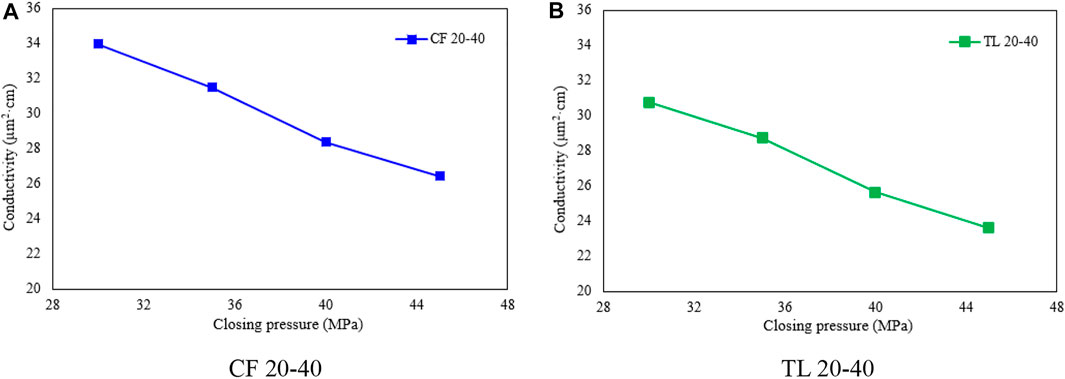
FIGURE 6. The conductivity of 20–40 mesh proppant varies with the closing pressure.
Secondly, Figure 7 shows the conductivity of 40–70 mesh proppant varies with the closing pressure, it can be seen that when the closing pressure is 30, 35, 40MPa, 45 MPa respectively, the conductivity of the proppant in CF is higher than that of the proppant produced in TL by 12.89%, 14.25%, 15.57%, 19.56%. Therefore, when the mesh number of proppant is 40–70, the proppant produced in CF own greater conductivity property.
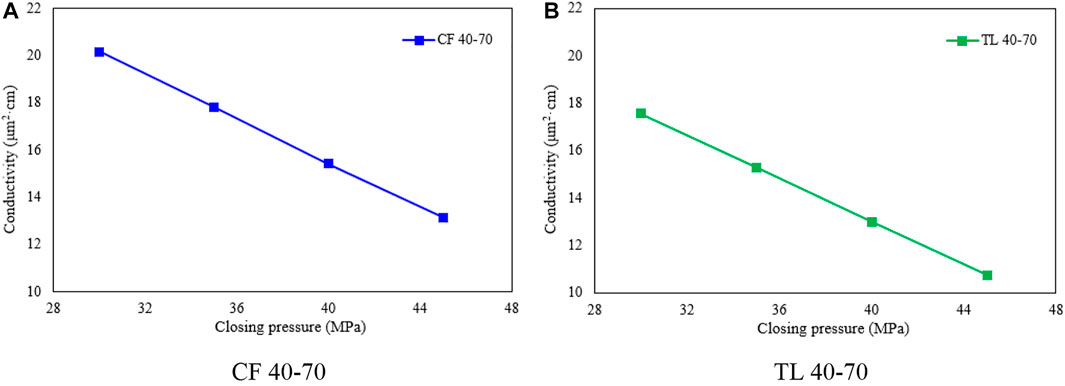
FIGURE 7. The conductivity of 40–70 mesh proppant varies with the closing pressure.
Finally, we compared the conductivity of proppant of CF 70–140 and TL 70–140 proppant. From Figure 8, we can see that with the closing pressure rises from 30 MPa to 35, 40, 45 MPa, the conductivity of the proppant of CF 70–140 is 33.75%, 39.41%, 48.14%, and 51.97% higher than that of the proppant produced in TL. Therefore, when the mesh number of proppants is 70–140, the proppant produced in CF will get a larger conductivity compared with TL.
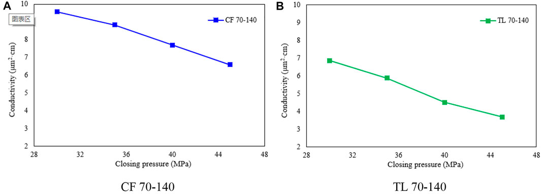
FIGURE 8. The conductivity of 70–140 mesh proppant varies with the closing pressure.
Through the above experiments, it can be seen that as the particle size of the proppant increases, the conductivity of the proppant gradually increases. Also, it can be known that at lower closing pressure, the proppant owns a low crushing rate and the proppant is still in the large particle size range, so its conductivity of propping fracture is relatively large. When the pressure is high, the crushing rate of proppant increases, the crushing phenomenon is very significant, and the proppant is mainly in the compaction state. At the same time, the small particle size after crushing has lower porosity, so its conductivity of propping fracture is significantly reduced. Moreover, the experiment also observed that the conductivity of proppant decreased faster within 24 h, but when the time exceeded 24 h, this trend gradually slowed down and stabilized.
4 Influence of sand paving concentration and closure pressure on long-term conductivity
According to the previous study, the sand properties and long-term conductivity of the proppant produced in CF own better performance than that of TL. Therefore, in this section, we take the quartz sand proppant produced in CF as an example to study the effects of sand paving concentration and closure pressure on long-term conductivity.
4.1 Proppant conductivity tests of CF 20–40 at different sand paving concentrations
Figure 9 shows the proppant conductivity of CF 20–40 at different sand paving concentrations and different closure pressures. It can be seen that when the sand paving concentration is equal to 1.25 or 2.5 kg/m2, due to the low sand paving concentration and the small thickness of the sand paving layer, under the conditions of closure pressure and fluid erosion, the proppant breaks and the fluid flow channel is formed, in this situation, the conductivity of propping fracture is relatively high. However, as the closing pressure increases, the degree of proppant crushing increases, and the broken particles fill the cracks, resulting in a decrease in the width of the fracture and conductivity decrease. Comparing the change of particle size before and after the experiment (Table 3), it can be seen that: when the sand paving concentration is 1.25 kg/m2, the average diameter of proppant decreases by 14.84%–16.39%; when the sand paving concentration is 2.5 kg/m2, the average diameter of proppant decreases by 16.07%–17.01%; when the sand paving concentration is 5 kg/m2, the average diameter of proppant decreases by 10.13%–15.19%; when the sand paving concentration is 7.5 kg/m2, the average diameter of proppant decreases by 14.39–15.57%.
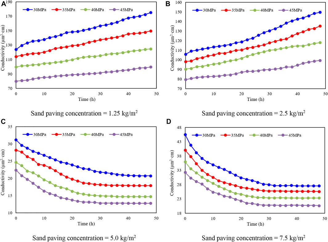
FIGURE 9. The proppant conductivity of CF 20–40 at different sand paving concentrations and different closure pressures.
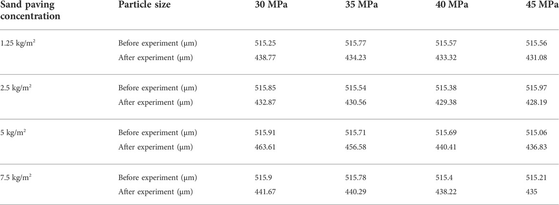
TABLE 3. Comparison of particle size changes before and after the conductivity experiment of proppant CF 20–40.
4.2 Proppant conductivity tests of CF 40–70 at different sand paving concentrations
Figure 10 shows the proppant conductivity of CF 40–70 at different sand paving concentrations and different closure pressures, and Table 4 shows the comparison of particle size changes before and after the conductivity experiment of proppant CF 40–70. It can be demonstrated that when the sand paving concentration is 1.25 kg/m2, the average diameter of proppant decreases by 21.21%–23.42%; when the sand paving concentration is 2.5 kg/m2, the average diameter of proppant decreases by 8.88%–14.83%; when the sand paving concentration is 5 kg/m2, the average diameter of proppant decreases by 8.07%–12.03%; when the sand paving concentration is 7.5 kg/m2, the average diameter of proppant decreases by 11.09–13.61%.
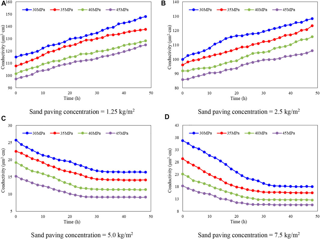
FIGURE 10. The proppant conductivity of CF 40–70 at different sand paving concentrations and different closure pressures.
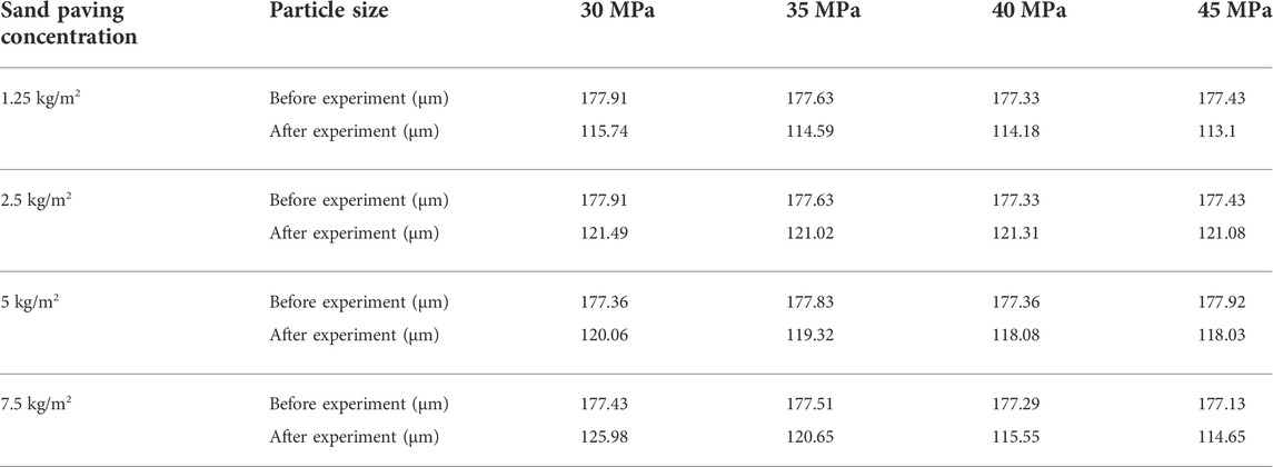
TABLE 4. Comparison of particle size changes before and after the conductivity experiment of proppant CF 70–140.
4.3 Proppant conductivity tests of CF 70–140 at different sand paving concentrations
Figure 11 shows the proppant conductivity of CF 70–140 at different sand paving concentrations and different closure pressures, and shows the comparison of particle size changes before and after the conductivity experiment of proppant CF 70–140. From Table 4 it can be seen that when the sand paving concentration is 1.25 kg/m2, the average diameter of proppant decreases by 34.94%–36.91%; when the sand paving concentration is 2.5 kg/m2, the average diameter of proppant decreases by 31.73%–31.8%; when the sand paving concentration is 5 kg/m2, the average diameter of proppant decreases by 32.31%–33.66%; when the sand paving concentration is 7.5 kg/m2, the average diameter of proppant decreases by 28.3%–35.27%.
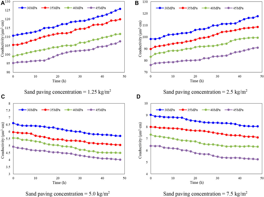
FIGURE 11. The proppant conductivity of CF 70–140 at different sand paving concentrations and different closure pressures.
Based on the research in Sections 4.1–4.3, it is can be found that the conductivity of proppant gradually decreased with the increase of the loading time, moreover, the rate of decrease gradually decreased, and finally the proppant conductivity trends to stabilized. When the sand paving concentration equal to 1.25 and 2.5 kg/m2, due to the low sanding concentration, there is only a thin layer in the diversion chamber. During the pressure loading process, part of proppant is broken, so the fluid is easy to penetrate the sand layer, therefore, the conductivity is large. With the continuous erosion of the fluid, the inner channel is gradually formed in the proppant fracture, hence, the conductivity increases gradually with the loading time. When the sand paving concentration equal to 5 and 7.5 kg/m2, the thickness of the sand paving is increased, the channel formation phenomenon will not occur, the flow conductivity is relatively low, and the conductivity of proppant always decreases with the increase of closing pressure.
In addition, from Figures 9, 10, 11, it can be seen that as the particle size of the proppant increases, the conductivity of the proppant gradually decreases. And with the increase of proppant paving concentration, the conductivity gradually increases, and the decline of conductivity gradually decreases. From Figures 9C, 10C, 11C, we found that no matter what the sand paving concentration is, the proppant’s conductivity always decreases with the increase of the closure pressure. With the increase of the proppant mesh, the conductivity of proppant gradually decreases, and the conductivity of sand paving concentration of 5 kg/m2 is less than that of 7.5 kg/m2.
5 Conclusion
Aiming at performance and conductivity capacity of quartz sand proppants, this study selected two kind of quartz sand from different producing area, Chifeng (CF), Tongliao (TL), and conducted a series of evaluation experiments, including proppant performance evaluation test, optimization experiment of long-term conductivity of quartz sand proppant, influence of sand paving concentration and closure pressure on long-term conductivity experiments. Through analysis and discussion of the experiment results, the following conclusions can be drawn.
1) Through the comprehensive experimental evaluation of six performance indicators including density, acid solubility, crushing rate, sphericity, screen analysis, turbidity, the results shown that the proppant performance of quartz sand produced in CF is better than that of produced in TL.
2) The long-term conductivity experiment results show that the conductivity of quartz sand proppant produced in CF is better than that of TL, and as the closing pressure increases, the conductivity of quartz sand gradually decreases. Moreover, under the same sanding concentration and closing pressure, the larger the particle size of the quartz sand, the higher the conductivity, and the greater the decrease in conductivity with the increase of the closing pressure.
3) In the influence of sand paving concentration, when the sand paving concentration is 1.25 and 2.5 kg/m2, the proppant filling layer is too thin, so the conductivity increases with the increase of closing pressure. In this situation, the test results of the API standard diversion chamber cannot reveal the actual conductivity. When the sand paving concentration is 5 and 7.5 kg/m2, the conductivity increases with the increase of the sand paving concentration. When the closing pressure increases, the decrease of conductivity of the flow decreases with the increase of the sand paving concentration. Therefore, increasing the sand paving concentration in the fracture is beneficial to maintain the conductivity of the fracture.
Data availability statement
The raw data supporting the conclusion of this article will be made available by the authors, without undue reservation.
Author contributions
J-GW: Writing, Methodology; X-JW: Conceptualization; X-FF: Formal analysis, Investigation; P-QG: Investigation; X-FZ: Supervision, Funding acquisition; Y-WL: Data Curation; YY: Resources; Y-HC: Investigation; BJ: Software, Writing; JW: Formal analysis.
Acknowledgments
We acknowledge the National Science and Technology Major Projects of China (2016ZX05023-005-001-003) and the National Natural Science Foundation Projects of China (51474070).
Conflict of interest
Author X-JW was employed by Daqing Oilfield Limited Company; Author P-QG was employed by Greatwall Drilling Company; Author BJ was employed by CNPC Offshore Engineering Company Limited; Author JW was employed by GWDC Drilling Engineering and Technology Research Institute.
The remaining authors declare that the research was conducted in the absence of any commercial or financial relationships that could be construed as a potential conflict of interest.
Publisher’s note
All claims expressed in this article are solely those of the authors and do not necessarily represent those of their affiliated organizations, or those of the publisher, the editors and the reviewers. Any product that may be evaluated in this article, or claim that may be made by its manufacturer, is not guaranteed or endorsed by the publisher.
References
Barree, R. D., Miskimins, J. L., and Duenckel, R. (2018). Generic correlations for proppant-pack conductivity. SPE Prod. Operations 33 (03), 509–521. doi:10.2118/179135-pa
Dong, L., and Lv, X. (2017). Influence of new proppant industry standard on quartz sand proppant. Technol. Superv. Petroleum Industry 33 (04), 33–36.
Fan, M., Han, Y., Gu, M., McClure, J., Ripepi, N., Westman, E., et al. (2020). Investigation of the conductivity of a proppant mixture using an experiment/simulation-integrated approach. J. Nat. Gas Sci. Eng. 78, 103234. doi:10.1016/j.jngse.2020.103234
Feng, D., Bakhshian, S., Wu, K., Song, Z., Ren, B., Li, J., et al. (2021). Wettability effects on phase behavior and interfacial tension in shale nanopores. Fuel 290, 119983. doi:10.1016/j.fuel.2020.119983
Fjaestad, D., and Tomac, I. (2019). Experimental investigation of sand proppant particles flow and transport regimes through narrow slots. Powder Technol. 343, 495–511. doi:10.1016/j.powtec.2018.11.004
Herskovits, R., Fuss-Dezelic, T., and Shi, J. (2016). Sand and ceramic proppant performance in thin layer/monolayer conditions subjected to cyclic stress. (Canton, OH, United States: SPE Eastern Regional Meeting).
Hu, K., Schmidt, A., and Barhaug, J. (2015). “Sand, resin-coated sand or ceramic proppant?,” in The Effect of Different Proppants on the Long-Term Production of Bakken Shale Wells[C]//SPE Annual Technical Conference and Exhibition OnePetro.
Huang, L., Zhou, W., Xu, H., Wang, L., Zou, J., and Zhou, Q. (2021). Dynamic fluid states in organic-inorganic nanocomposite: Implications for shale gas recovery and CO2 sequestration. Chem. Eng. J. 411, 128423. doi:10.1016/j.cej.2021.128423
Jia, X. (2011). The applications and agent status of propping agent in China. Technol. Dev. Enterp. 30 (19), 105–106.
Kou, S., Chen, S., He, L., and Liao, K. (2018). Adaptability of quartz sand for fracturing of Sulige tight sand gas reservoir. Reserv. Eval. Dev. 9 (2), 65–70.
Liang, F., Sayed, M., and Al-Muntasheri, G. (2015). Overview of existing proppant technologies and challenges. (Manama, Bahrain: SPE Middle East Oil & Gas Show and Conference).
Liang, T., and Yan, Y. (2021). Analysis of influence factor of the proppants crush resistance in hydraulic fracturing. J. Chongqing Univ. Sci. Technol. 23 (03), 10–14+44.
Maity, D., and Ciezobka, J. (2019). An interpretation of proppant transport within the stimulated rock volume at the hydraulic-fracturing test site in the permian basin. SPE Reserv. Eval. Eng. 22 (02), 477–491. doi:10.2118/194496-pa
Man, S., and Wong, R. C. K. (2017). Compression and crushing behavior of ceramic proppants and sand under high stresses. J. Petroleum Sci. Eng. 158, 268–283. doi:10.1016/j.petrol.2017.08.052
Olmen, B. D., Anschutz Donald, A., and Brannon Harold, D. (2018). Evolving proppant supply and demand: The implications on the hydraulic fracturing industry. (Dallas, TX, United States: SPE Annual Technical Conference and Exhibition).
Olsen, T. N., Bratton, T. R., and Thiercelin, M. J. (2009). Quantifying proppant transport for complex fractures in unconventional formations. SPE Hydraulic Fracturing Technology Conference.
Srinivasan, K., Ajisafe, F., and Alimahomed, F. (2018). Is there anything called too much proppant? (Midland, TX, United States: SPE Liquids-Rich Basins Conference-North America).
Su, Y., Zhao, Q., and Yao, J. (2020). Preparation and performance evaluation of hydrophobic quartz sand treated by OTS-SAM technology. Mod. Chem. Ind. 40 (6), 165–174.
Sun, Z., Huang, B., Li, Y., Lin, H., Shi, S., and Yu, W. (2022a). Nanoconfined methane flow behavior through realistic organic shale matrix under displacement pressure: A molecular simulation investigation. J. Pet. Explor. Prod. Technol. 12 (4), 1193–1201. doi:10.1007/s13202-021-01382-0
Sun, Z., Wang, S., Xiong, H., Wu, K., and Shi, J. (2022b). Optimal nanocone geometry for water flow. AIChE J. 68 (3), e17543. doi:10.1002/aic.17543
Sun, Z., Huang, B., Wu, K., Shi, S., Wu, Z., Hou, M., et al. (2022c). Nanoconfined methane density over pressure and temperature: Wettability effect. J. Nat. gas Sci. Eng. 99, 104426. doi:10.1016/j.jngse.2022.104426
Syfan, F. E., Palisch, T. T., and Dawson, J. C. (2013). 65 Years of fracturing experience: The key to better productivity is not what we have learned but what we have forgotten and failed to utilize. (New Orleans, LA, United States: SPE Annual Technical Conference and Exhibition).
Tasqué, J. E., Vega, I. N., Marco, S., Raffo, P. A., and D'Accorso, N. B. (2021). Ultra-light weight proppant: Synthesis, characterization, and performance of new proppants. J. Nat. Gas Sci. Eng. 85, 103717. doi:10.1016/j.jngse.2020.103717
Yuwei, L., Dan, J., Zhenhua, R., Jiyong, C., Chunkai, F., and Jun, Z. (2017). Evaluation method of rck brittleness based on statistical constitutive relations for rock damage. J. Pet. Sci. Eng. 153, 123–132.
Yuwei, L., Min, L., Jizhou, T., Mian, C., and Xiaofei, F. (2020). A Hydraulic fracture height mathematical model considering the influence of plastic region at fracture tip. Pet. Explor. Dev. 47, 184–195.
Yuwei, L., Min, L., Lihua, Z., Wei, L., and Wanchun, Z. (2019). Brittleness evaluation of coal based on statistical damage and energy evolution theory. J. Pet. Sci. Eng. 172, 753–763.
Zhang, F., Zhu, H., Zhou, H., Guo, J., and Huang, B. (2017). Discrete-element-method/computational-fluid-dynamics coupling simulation of proppant embedment and fracture conductivity after hydraulic fracturing. SPE J. 22, 632–644. doi:10.2118/185172-pa
Zhang, T., Li, X., Sun, Z., Feng, D., Miao, Y., Li, P., et al. (2017). An analytical model for relative permeability in water-wet nanoporous media. Chem. Eng. Sci. 174, 1–12. doi:10.1016/j.ces.2017.08.023
Zhang, J., Zhu, D., and Hill, A. D. (2016). Water-induced damage to propped-fracture conductivity in shale formations. SPE Prod. Operations 31 (02), 147–156. doi:10.2118/173346-pa
Zhao, W., Zhang, T., Jia, C., Li, X., Wu, K., and He, M. (2020). Numerical simulation on natural gas migration and accumulation in sweet spots of tight reservoir. J. Nat. Gas Sci. Eng. 81, 103454. doi:10.1016/j.jngse.2020.103454
Keywords: quartz sand proppant, conductivity, proppant performance, proppant particle size, sand paving concentration
Citation: Wei J-G, Wang X-J, Fu X-F, Gong P-Q, Zhou X-F, Li Y-W, Yang Y, Chen Y-H, Jia B and Wu J (2022) Optimization of long-term fracture conductivity with quartz: An experimental investigation. Front. Energy Res. 10:973349. doi: 10.3389/fenrg.2022.973349
Received: 20 June 2022; Accepted: 25 July 2022;
Published: 23 August 2022.
Edited by:
Zheng Sun, China University of Mining and Technology, ChinaReviewed by:
Wen Zhao, Research Institute of Petroleum Exploration and Development (RIPED), ChinaQian Wang, China University of Mining and Technology, China
Yisheng Liu, Chengdu University of Technology, China
Copyright © 2022 Wei, Wang, Fu, Gong, Zhou, Li, Yang, Chen, Jia and Wu. This is an open-access article distributed under the terms of the Creative Commons Attribution License (CC BY). The use, distribution or reproduction in other forums is permitted, provided the original author(s) and the copyright owner(s) are credited and that the original publication in this journal is cited, in accordance with accepted academic practice. No use, distribution or reproduction is permitted which does not comply with these terms.
*Correspondence: Xiao-Feng Zhou, emhvdV94aWFvZmVuZzE5OTNAMTYzLmNvbQ==